2006 NISSAN PATROL stop start
[x] Cancel search: stop startPage 202 of 1226
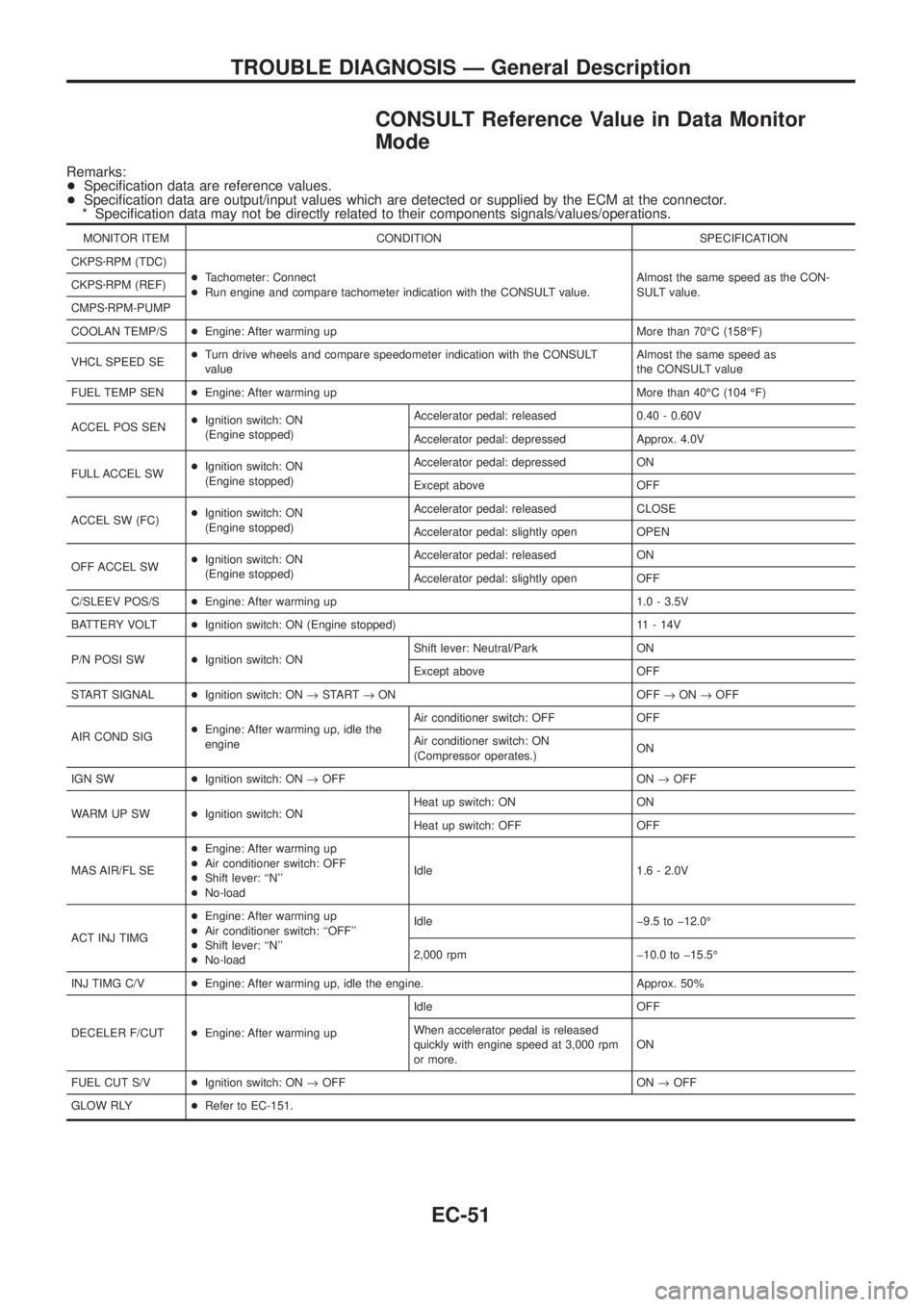
CONSULT Reference Value in Data Monitor
Mode
Remarks:
+Speci®cation data are reference values.
+Speci®cation data are output/input values which are detected or supplied by the ECM at the connector.
* Speci®cation data may not be directly related to their components signals/values/operations.
MONITOR ITEM CONDITION SPECIFICATION
CKPSzRPM (TDC)
+Tachometer: Connect
+Run engine and compare tachometer indication with the CONSULT value.Almost the same speed as the CON-
SULT value. CKPSzRPM (REF)
CMPSzRPM-PUMP
COOLAN TEMP/S+Engine: After warming up More than 70ÉC (158ÉF)
VHCL SPEED SE+Turn drive wheels and compare speedometer indication with the CONSULT
valueAlmost the same speed as
the CONSULT value
FUEL TEMP SEN+Engine: After warming up More than 40ÉC (104 ÉF)
ACCEL POS SEN+Ignition switch: ON
(Engine stopped)Accelerator pedal: released 0.40 - 0.60V
Accelerator pedal: depressed Approx. 4.0V
FULL ACCEL SW+Ignition switch: ON
(Engine stopped)Accelerator pedal: depressed ON
Except above OFF
ACCEL SW (FC)+Ignition switch: ON
(Engine stopped)Accelerator pedal: released CLOSE
Accelerator pedal: slightly open OPEN
OFF ACCEL SW+Ignition switch: ON
(Engine stopped)Accelerator pedal: released ON
Accelerator pedal: slightly open OFF
C/SLEEV POS/S+Engine: After warming up 1.0 - 3.5V
BATTERY VOLT+Ignition switch: ON (Engine stopped) 11 - 14V
P/N POSI SW+Ignition switch: ONShift lever: Neutral/Park ON
Except above OFF
START SIGNAL+Ignition switch: ON®START®ON OFF®ON®OFF
AIR COND SIG+Engine: After warming up, idle the
engineAir conditioner switch: OFF OFF
Air conditioner switch: ON
(Compressor operates.)ON
IGN SW+Ignition switch: ON®OFF ON®OFF
WARM UP SW+Ignition switch: ONHeat up switch: ON ON
Heat up switch: OFF OFF
MAS AIR/FL SE+Engine: After warming up
+Air conditioner switch: OFF
+Shift lever: ``N''
+No-loadIdle 1.6 - 2.0V
ACT INJ TIMG+Engine: After warming up
+Air conditioner switch: ``OFF''
+Shift lever: ``N''
+No-loadIdle þ9.5 to þ12.0É
2,000 rpm þ10.0 to þ15.5É
INJ TIMG C/V+Engine: After warming up, idle the engine. Approx. 50%
DECELER F/CUT+Engine: After warming upIdle OFF
When accelerator pedal is released
quickly with engine speed at 3,000 rpm
or more.ON
FUEL CUT S/V+Ignition switch: ON®OFF ON®OFF
GLOW RLY+Refer to EC-151.
TROUBLE DIAGNOSIS Ð General Description
EC-51
Page 217 of 1226
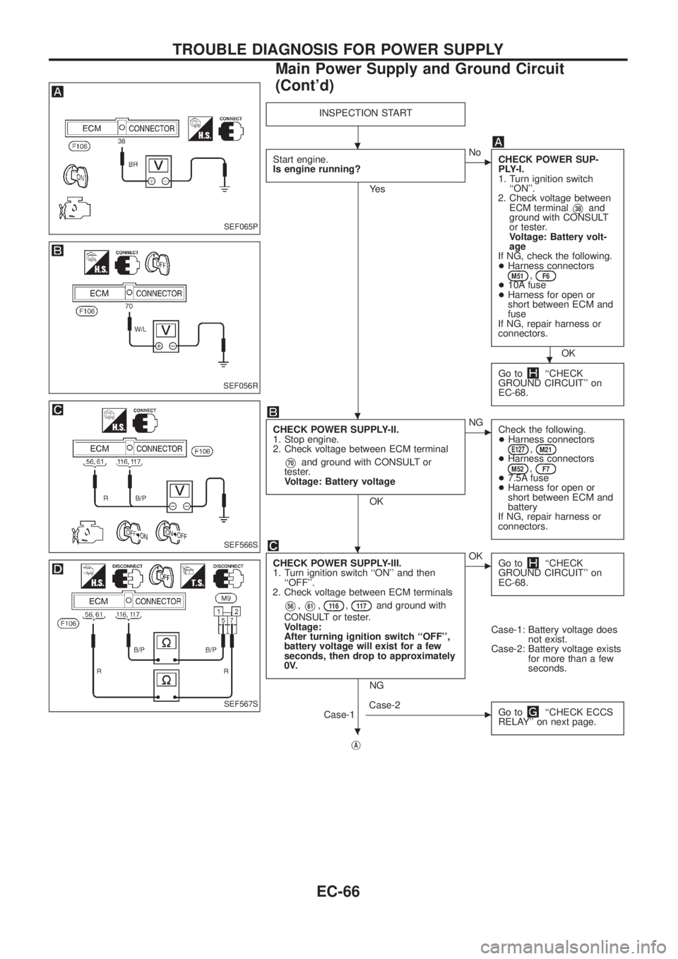
INSPECTION START
Start engine.
Is engine running?
Ye s
cNo
CHECK POWER SUP-
PLY-I.
1. Turn ignition switch
``ON''.
2. Check voltage between
ECM terminal
V38and
ground with CONSULT
or tester.
Voltage: Battery volt-
age
If NG, check the following.
+Harness connectors
M51,F6+10A fuse
+Harness for open or
short between ECM and
fuse
If NG, repair harness or
connectors.
OK
Go to
``CHECK
GROUND CIRCUIT'' on
EC-68.
CHECK POWER SUPPLY-II.
1. Stop engine.
2. Check voltage between ECM terminal
V70and ground with CONSULT or
tester.
Voltage: Battery voltage
OK
cNG
Check the following.
+Harness connectors
E127,M21+Harness connectorsM52,F7+7.5A fuse
+Harness for open or
short between ECM and
battery
If NG, repair harness or
connectors.
CHECK POWER SUPPLY-III.
1. Turn ignition switch ``ON'' and then
``OFF''.
2. Check voltage between ECM terminals
V56,V61,11 6,11 7and ground with
CONSULT or tester.
Voltage:
After turning ignition switch ``OFF'',
battery voltage will exist for a few
seconds, then drop to approximately
0V.
NG
cOK
Go to``CHECK
GROUND CIRCUIT'' on
EC-68.
Case-1: Battery voltage does
not exist.
Case-2: Battery voltage exists
for more than a few
seconds.
Case-1
cCase-2
Go to``CHECK ECCS
RELAY'' on next page.
jA
SEF065P
SEF056R
SEF566S
SEF567S
.
.
.
.
.
TROUBLE DIAGNOSIS FOR POWER SUPPLY
Main Power Supply and Ground Circuit
(Cont'd)
EC-66
Page 229 of 1226
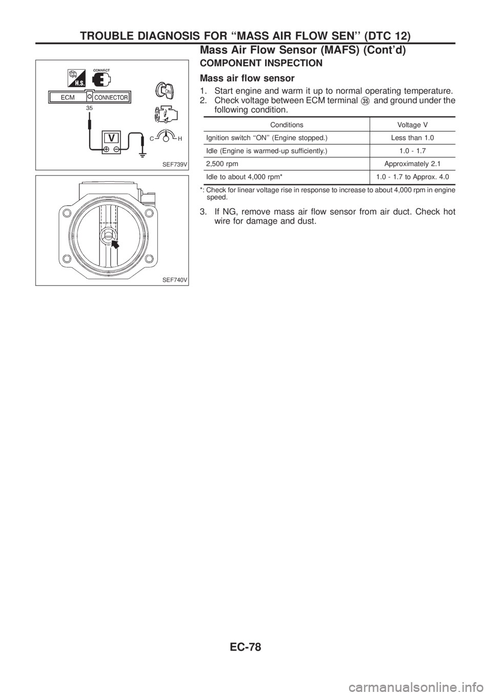
COMPONENT INSPECTION
Mass air ¯ow sensor
1. Start engine and warm it up to normal operating temperature.
2. Check voltage between ECM terminal
V35and ground under the
following condition.
Conditions Voltage V
Ignition switch ``ON'' (Engine stopped.) Less than 1.0
Idle (Engine is warmed-up sufficiently.) 1.0 - 1.7
2,500 rpm Approximately 2.1
Idle to about 4,000 rpm* 1.0 - 1.7 to Approx. 4.0
*: Check for linear voltage rise in response to increase to about 4,000 rpm in engine
speed.
3. If NG, remove mass air ¯ow sensor from air duct. Check hot
wire for damage and dust.
SEF739V
SEF740V
TROUBLE DIAGNOSIS FOR ``MASS AIR FLOW SEN'' (DTC 12)
Mass Air Flow Sensor (MAFS) (Cont'd)
EC-78
Page 329 of 1226
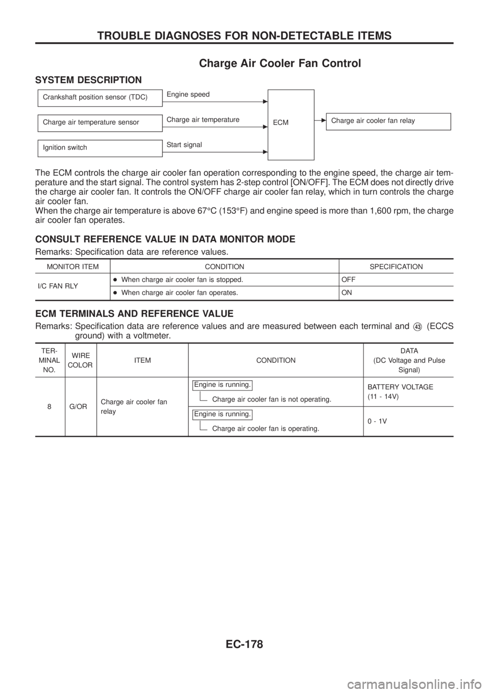
Charge Air Cooler Fan Control
SYSTEM DESCRIPTION
Crankshaft position sensor (TDC)cEngine speed
ECM
cCharge air cooler fan relayCharge air temperature sensorcCharge air temperature
Ignition switch
cStart signal
The ECM controls the charge air cooler fan operation corresponding to the engine speed, the charge air tem-
perature and the start signal. The control system has 2-step control [ON/OFF]. The ECM does not directly drive
the charge air cooler fan. It controls the ON/OFF charge air cooler fan relay, which in turn controls the charge
air cooler fan.
When the charge air temperature is above 67ÉC (153ÉF) and engine speed is more than 1,600 rpm, the charge
air cooler fan operates.
CONSULT REFERENCE VALUE IN DATA MONITOR MODE
Remarks: Speci®cation data are reference values.
MONITOR ITEM CONDITION SPECIFICATION
I/C FAN RLY+When charge air cooler fan is stopped. OFF
+When charge air cooler fan operates. ON
ECM TERMINALS AND REFERENCE VALUE
Remarks: Speci®cation data are reference values and are measured between each terminal andV43(ECCS
ground) with a voltmeter.
TER-
MINAL
NO.WIRE
COLORITEM CONDITIONDATA
(DC Voltage and Pulse
Signal)
8 G/ORCharge air cooler fan
relayEngine is running.
Charge air cooler fan is not operating.BATTERY VOLTAGE
(11 - 14V)
Engine is running.
Charge air cooler fan is operating.0-1V
TROUBLE DIAGNOSES FOR NON-DETECTABLE ITEMS
EC-178
Page 331 of 1226
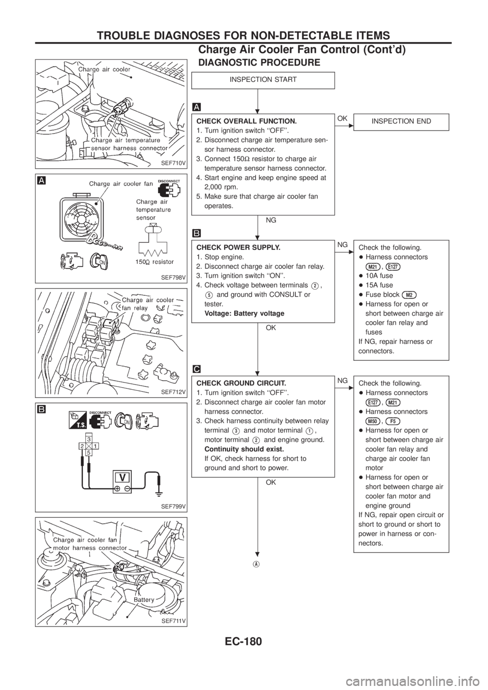
DIAGNOSTIC PROCEDURE
INSPECTION START
CHECK OVERALL FUNCTION.
1. Turn ignition switch ``OFF''.
2. Disconnect charge air temperature sen-
sor harness connector.
3. Connect 150Wresistor to charge air
temperature sensor harness connector.
4. Start engine and keep engine speed at
2,000 rpm.
5. Make sure that charge air cooler fan
operates.
NG
cOK
INSPECTION END
CHECK POWER SUPPLY.
1. Stop engine.
2. Disconnect charge air cooler fan relay.
3. Turn ignition switch ``ON''.
4. Check voltage between terminals
V2,
V5and ground with CONSULT or
tester.
Voltage: Battery voltage
OK
cNG
Check the following.
+Harness connectors
M21,E127
+10A fuse
+15A fuse
+Fuse block
M2
+Harness for open or
short between charge air
cooler fan relay and
fuses
If NG, repair harness or
connectors.
CHECK GROUND CIRCUIT.
1. Turn ignition switch ``OFF''.
2. Disconnect charge air cooler fan motor
harness connector.
3. Check harness continuity between relay
terminal
V3and motor terminalV1,
motor terminal
V2and engine ground.
Continuity should exist.
If OK, check harness for short to
ground and short to power.
OK
cNG
Check the following.
+Harness connectors
E127,M21
+Harness connectors
M50,F5
+Harness for open or
short between charge air
cooler fan relay and
charge air cooler fan
motor
+Harness for open or
short between charge air
cooler fan motor and
engine ground
If NG, repair open circuit or
short to ground or short to
power in harness or con-
nectors.
jA
SEF710V
SEF798V
SEF712V
SEF799V
SEF711V
.
.
.
.
TROUBLE DIAGNOSES FOR NON-DETECTABLE ITEMS
Charge Air Cooler Fan Control (Cont'd)
EC-180
Page 387 of 1226
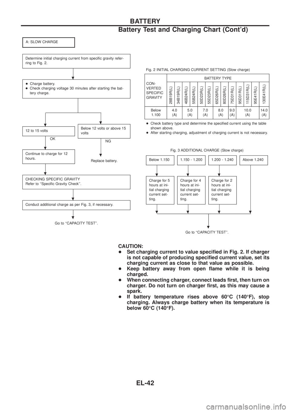
A: SLOW CHARGE
Determine initial charging current from speci®c gravity refer-
ring to Fig. 2.
+Charge battery.
+Check charging voltage 30 minutes after starting the bat-
tery charge.
12 to 15 volts
OKBelow 12 volts or above 15
voltsNG
Continue to charge for 12
hours.
Replace battery.
CHECKING SPECIFIC GRAVITY
Refer to ``Speci®c Gravity Check''.
Conduct additional charge as per Fig. 3, if necessary.
Go to ``CAPACITY TEST''.Fig. 2 INITIAL CHARGING CURRENT SETTING (Slow charge)
CON-
VERTED
SPECIFIC
GRAVITYBATTERY TYPE
28B19R(L)
34B19R(L)
46B24R(L)
55B24R(L)
50D23R(L)
55D23R(L)
65D26R(L)
80D26R(L)
75D31R(L)
95D31R(L)
115D31R(L)
95E41R(L)
130E41R(L)
Below
1.1004.0
(A)5.0
(A)7.0
(A)8.0
(A)9.0
(A)10.0
(A)14.0
(A)
+Check battery type and determine the speci®ed current using the table
shown above.
+After starting charging, adjustment of charging current is not necessary.
Fig. 3 ADDITIONAL CHARGE (Slow charge)
Below 1.150
1.150 - 1.2001.200 - 1.240Above 1.240
Charge for 5
hours at ini-
tial charging
current set-
ting.Charge for 4
hours at ini-
tial charging
current set-
ting.Charge for 2
hours at ini-
tial charging
current set-
ting.
Go to ``CAPACITY TEST''.
.
CAUTION:
+Set charging current to value speci®ed in Fig. 2. If charger
is not capable of producing speci®ed current value, set its
charging current as close to that value as possible.
+Keep battery away from open ¯ame while it is being
charged.
+When connecting charger, connect leads ®rst, then turn on
charger. Do not turn on charger ®rst, as this may cause a
spark.
+If battery temperature rises above 60ÉC (140ÉF), stop
charging. Always charge battery when its temperature is
below 60ÉC (140ÉF).
.
..
.
.
.
.
.
...
....
BATTERY
Battery Test and Charging Chart (Cont'd)
EL-42
Page 388 of 1226
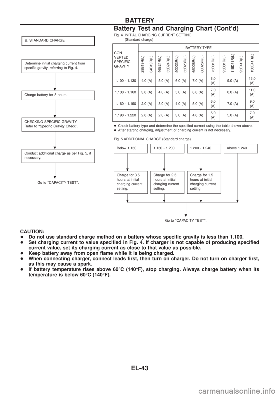
B: STANDARD CHARGE
Determine initial charging current from
speci®c gravity, referring to Fig. 4.
Charge battery for 8 hours.
CHECKING SPECIFIC GRAVITY
Refer to ``Speci®c Gravity Check''.
Conduct additional charge as per Fig. 5, if
necessary.
Go to ``CAPACITY TEST''.Fig. 4 INITIAL CHARGING CURRENT SETTING
(Standard charge)
CON-
VERTED
SPECIFIC
GRAVITYBATTERY TYPE
28B19R(L)
34B19R(L)
46B24R(L)
55B24R(L)
50D23R(L)
55D23R(L)
65D26R(L)
80D26R(L)
75D31R(L)
95D31R(L)
115D31R(L)
95E41R(L)
130E41R(L)
1.100 - 1.130 4.0 (A) 5.0 (A) 6.0 (A) 7.0 (A)8.0
(A)9.0 (A)13.0
(A)
1.130 - 1.160 3.0 (A) 4.0 (A) 5.0 (A) 6.0 (A)7.0
(A)8.0 (A)11.0
(A)
1.160 - 1.190 2.0 (A) 3.0 (A) 4.0 (A) 5.0 (A)6.0
(A)7.0 (A)9.0
(A)
1.190 - 1.220 2.0 (A) 2.0 (A) 3.0 (A) 4.0 (A)5.0
(A)5.0 (A)7.0
(A)
+Check battery type and determine the speci®ed current using the table shown above.
+After starting charging, adjustment of charging current is not necessary.
Fig. 5 ADDITIONAL CHARGE (Standard charge)
Below 1.150
1.150 - 1.2001.200 - 1.240Above 1.240
Charge for 3.5
hours at initial
charging current
setting.Charge for 2.5
hours at initial
charging current
setting.Charge for 1.5
hours at initial
charging current
setting.
Go to ``CAPACITY TEST''.
.
CAUTION:
+Do not use standard charge method on a battery whose speci®c gravity is less than 1.100.
+Set charging current to value speci®ed in Fig. 4. If charger is not capable of producing speci®ed
current value, set its charging current as close to that value as possible.
+Keep battery away from open ¯ame while it is being charged.
+When connecting charger, connect leads ®rst, then turn on charger. Do not turn on charger ®rst,
as this may cause a spark.
+If battery temperature rises above 60ÉC (140ÉF), stop charging. Always charge battery when its
temperature is below 60ÉC (140ÉF).
.
.
.
.
...
....
BATTERY
Battery Test and Charging Chart (Cont'd)
EL-43
Page 389 of 1226
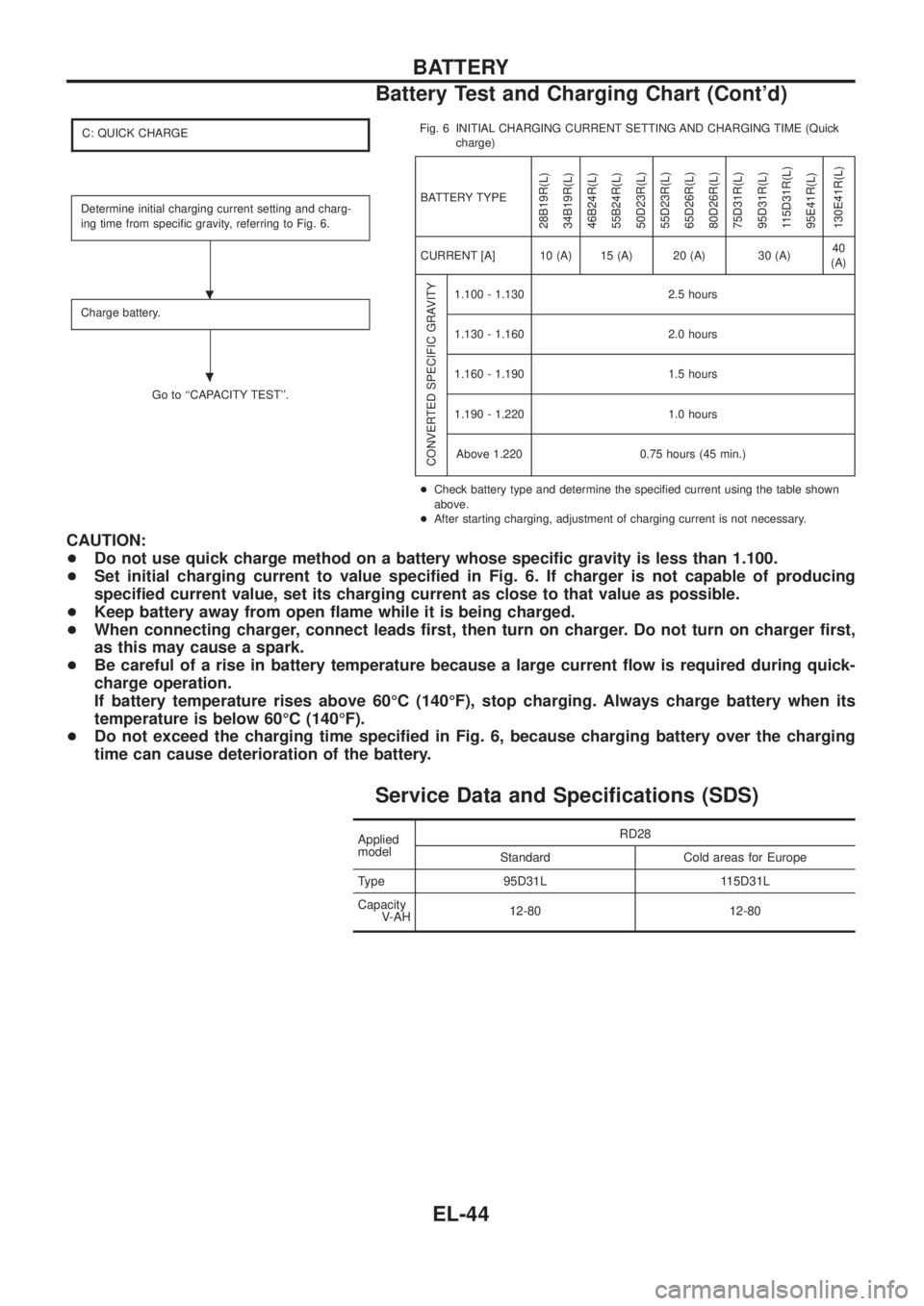
C: QUICK CHARGE
Determine initial charging current setting and charg-
ing time from speci®c gravity, referring to Fig. 6.
Charge battery.
Go to ``CAPACITY TEST''.Fig. 6 INITIAL CHARGING CURRENT SETTING AND CHARGING TIME (Quick
charge)
BATTERY TYPE
28B19R(L)
34B19R(L)
46B24R(L)
55B24R(L)
50D23R(L)
55D23R(L)
65D26R(L)
80D26R(L)
75D31R(L)
95D31R(L)
115D31R(L)
95E41R(L)
130E41R(L)
CURRENT [A] 10 (A) 15 (A) 20 (A) 30 (A)40
(A)
CONVERTED SPECIFIC GRAVITY
1.100 - 1.130 2.5 hours
1.130 - 1.160 2.0 hours
1.160 - 1.190 1.5 hours
1.190 - 1.220 1.0 hours
Above 1.220 0.75 hours (45 min.)
+Check battery type and determine the speci®ed current using the table shown
above.
+After starting charging, adjustment of charging current is not necessary.
CAUTION:
+Do not use quick charge method on a battery whose speci®c gravity is less than 1.100.
+Set initial charging current to value speci®ed in Fig. 6. If charger is not capable of producing
speci®ed current value, set its charging current as close to that value as possible.
+Keep battery away from open ¯ame while it is being charged.
+When connecting charger, connect leads ®rst, then turn on charger. Do not turn on charger ®rst,
as this may cause a spark.
+Be careful of a rise in battery temperature because a large current ¯ow is required during quick-
charge operation.
If battery temperature rises above 60ÉC (140ÉF), stop charging. Always charge battery when its
temperature is below 60ÉC (140ÉF).
+Do not exceed the charging time speci®ed in Fig. 6, because charging battery over the charging
time can cause deterioration of the battery.
Service Data and Speci®cations (SDS)
Applied
modelRD28
Standard Cold areas for Europe
Type 95D31L 115D31L
Capacity
V-AH12-80 12-80
.
.
BATTERY
Battery Test and Charging Chart (Cont'd)
EL-44