2006 NISSAN PATROL checking oil
[x] Cancel search: checking oilPage 866 of 1226
jA
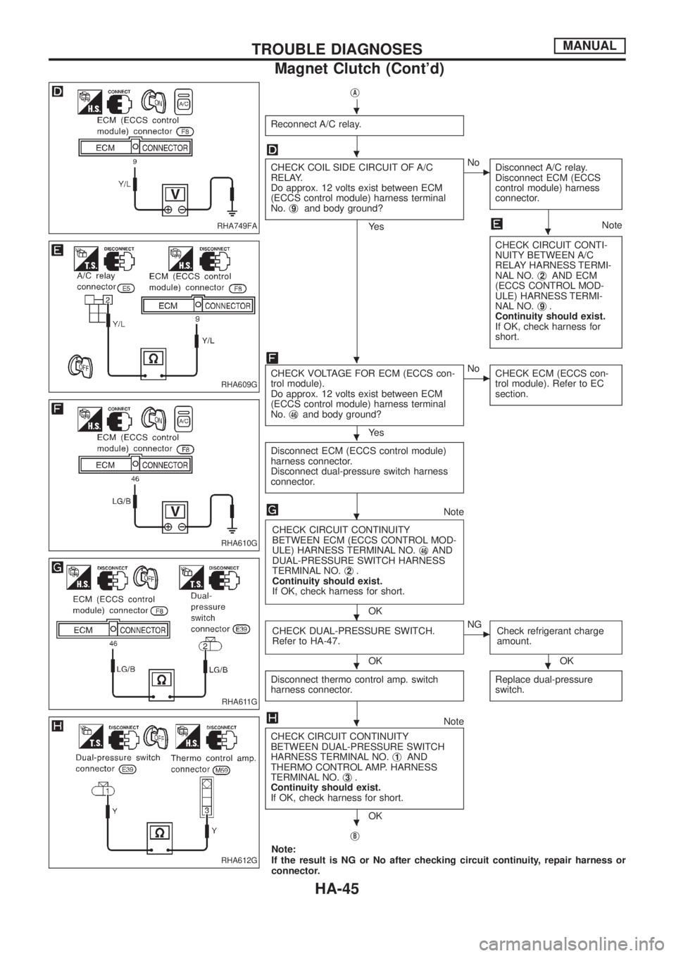
Reconnect A/C relay.
CHECK COIL SIDE CIRCUIT OF A/C
RELAY.
Do approx. 12 volts exist between ECM
(ECCS control module) harness terminal
No.j
9and body ground?
Ye s
cNo
Disconnect A/C relay.
Disconnect ECM (ECCS
control module) harness
connector.
Note
CHECK CIRCUIT CONTI-
NUITY BETWEEN A/C
RELAY HARNESS TERMI-
NAL NO.j
2AND ECM
(ECCS CONTROL MOD-
ULE) HARNESS TERMI-
NAL NO.j
9.
Continuity should exist.
If OK, check harness for
short.
CHECK VOLTAGE FOR ECM (ECCS con-
trol module).
Do approx. 12 volts exist between ECM
(ECCS control module) harness terminal
No.j
46and body ground?
Ye s
cNo
CHECK ECM (ECCS con-
trol module). Refer to EC
section.
Disconnect ECM (ECCS control module)
harness connector.
Disconnect dual-pressure switch harness
connector.
Note
CHECK CIRCUIT CONTINUITY
BETWEEN ECM (ECCS CONTROL MOD-
ULE) HARNESS TERMINAL NO.j
46AND
DUAL-PRESSURE SWITCH HARNESS
TERMINAL NO.j
2.
Continuity should exist.
If OK, check harness for short.
OK
CHECK DUAL-PRESSURE SWITCH.
Refer to HA-47.
OK
cNG
Check refrigerant charge
amount.
OK
Disconnect thermo control amp. switch
harness connector.
Replace dual-pressure
switch.
Note
CHECK CIRCUIT CONTINUITY
BETWEEN DUAL-PRESSURE SWITCH
HARNESS TERMINAL NO.j
1AND
THERMO CONTROL AMP. HARNESS
TERMINAL NO.j
3.
Continuity should exist.
If OK, check harness for short.
OK
j
B
Note:
If the result is NG or No after checking circuit continuity, repair harness or
connector.
RHA749FA
RHA609G
RHA610G
RHA611G
RHA612G
.
.
.
.
.
.
.
..
.
.
TROUBLE DIAGNOSESMANUAL
Magnet Clutch (Cont'd)
HA-45
Page 915 of 1226
DIAGNOSTIC PROCEDURE
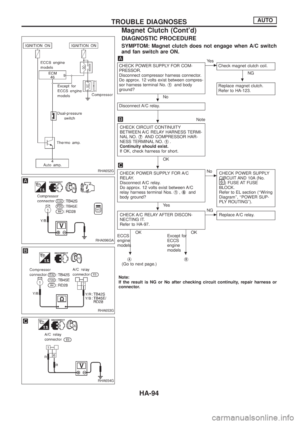
SYMPTOM: Magnet clutch does not engage when A/C switch
and fan switch are ON.
CHECK POWER SUPPLY FOR COM-
PRESSOR.
Disconnect compressor harness connector.
Do approx. 12 volts exist between compres-
sor harness terminal No.j
1and body
ground?
No
cYe s
Check magnet clutch coil.
NG
Replace magnet clutch.
Refer to HA-123.
Disconnect A/C relay.
Note
CHECK CIRCUIT CONTINUITY
BETWEEN A/C RELAY HARNESS TERMI-
NAL NO.j
7AND COMPRESSOR HAR-
NESS TERMINAL NO.j1.
Continuity should exist.
If OK, check harness for short.
OK
CHECK POWER SUPPLY FOR A/C
RELAY.
Disconnect A/C relay.
Do approx. 12 volts exist between A/C
relay harness terminal Nos.j
1,j6and
body ground?
Ye s
cNo
CHECK POWER SUPPLY
CIRCUIT AND 10A (No.
) FUSE AT FUSE
BLOCK.
Refer to EL section (``Wiring
Diagram'', ``POWER SUP-
PLY ROUTING'').
CHECK A/C RELAY AFTER DISCON-
NECTING IT.
Refer to HA-97.
OK OK
ECCS
engine
modelsExcept for
ECCS
engine
models
cNG
Replace A/C relay.
jA(Go to next page.)jB
Note:
If the result is NG or No after checking circuit continuity, repair harness or
connector.
RHA652G
RHA096GA
RHA653G
RHA654G
.
.
.
.
.
..
TROUBLE DIAGNOSESAUTO
Magnet Clutch (Cont'd)
HA-94
Page 916 of 1226

jA
Reconnect A/C relay.
CHECK COIL SIDE CIRCUIT OF A/C
RELAY.
Do approx. 12 volts exist between ECM
(ECCS control module) harness terminal
No.j
9and body ground?
Ye s
cNo
Disconnect A/C relay.
Disconnect ECM (ECCS
control module) harness
connector.
Note
CHECK CIRCUIT CONTI-
NUITY BETWEEN A/C
RELAY HARNESS TERMI-
NAL NO.j
2AND ECM
(ECCS CONTROL MOD-
ULE) HARNESS TERMI-
NAL NO.j
9.
Continuity should exist.
If OK, check harness for
short.
CHECK VOLTAGE FOR ECM (ECCS con-
trol module).
Do approx. 12 volts exist between ECM
(ECCS control module) harness terminal
No.j
46and body ground?
Ye s
cNo
CHECK ECM (ECCS con-
trol module). Refer to EC
section.
Disconnect ECM (ECCS control module)
harness connector.
Disconnect dual-pressure switch harness
connector.
Note
CHECK CIRCUIT CONTINUITY
BETWEEN ECM (ECCS CONTROL MOD-
ULE) HARNESS TERMINAL NO.j
46,j21
AND DUAL-PRESSURE SWITCH HAR-
NESS TERMINAL NO.j
2.
Continuity should exist.
If OK, check harness for short.
OK
CHECK DUAL-PRESSURE SWITCH.
Refer to HA-97.
OK
cNG
Replace dual-pressure
switch.
jC
Note:
If the result is NG or No after checking circuit continuity, repair harness
or connector.
RHA655G
RHA656G
RHA657G
RHA658G
.
.
.
.
.
.
.
.
TROUBLE DIAGNOSESAUTO
Magnet Clutch (Cont'd)
HA-95
Page 935 of 1226
Maintenance of Lubricant Quantity in
Compressor
The lubricant used to lubricate the compressor circulates through
the system with the refrigerant. Add lubricant to compressor when
replacing any component or after a large gas leakage occurred. It
is important to maintain the speci®ed amount.
If lubricant quantity is not maintained properly, the following mal-
functions may result:
+Lack of lubricant: May lead to a seized compressor
+Excessive lubricant: Inadequate cooling (thermal exchange
interference)
LUBRICANT
Name: Nissan A/C System Oil Type S
Part number: KLH00-PAGS0
CHECKING AND ADJUSTING
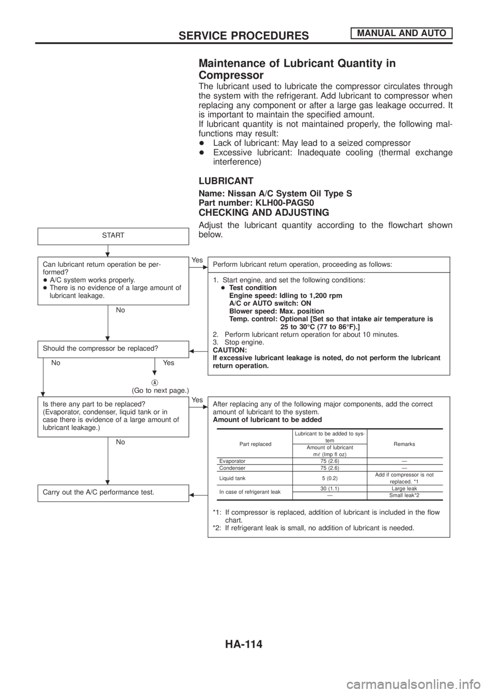
Adjust the lubricant quantity according to the ¯owchart shown
below.
START
Can lubricant return operation be per-
formed?
+A/C system works properly.
+There is no evidence of a large amount of
lubricant leakage.
No
cYe s
Perform lubricant return operation, proceeding as follows:
------------------------------------------------------------------------------------------------------------------------------------------------------------------------------------------------------------------------------------------------------------------------------------------------------------------------------------------------------------------------------------------------------------------------------------------------------------------------------------------------------------------------------------
1. Start engine, and set the following conditions:
+Test condition
Engine speed: Idling to 1,200 rpm
A/C or AUTO switch: ON
Blower speed: Max. position
Temp. control: Optional [Set so that intake air temperature is
25 to 30ÉC (77 to 86ÉF).]
2. Perform lubricant return operation for about 10 minutes.
3. Stop engine.
CAUTION:
If excessive lubricant leakage is noted, do not perform the lubricant
return operation.
Should the compressor be replaced?
No Yes
b
jA(Go to next page.)
Is there any part to be replaced?
(Evaporator, condenser, liquid tank or in
case there is evidence of a large amount of
lubricant leakage.)
No
cYe s
After replacing any of the following major components, add the correct
amount of lubricant to the system.
Amount of lubricant to be added
*1: If compressor is replaced, addition of lubricant is included in the ¯ow
chart.
*2: If refrigerant leak is small, no addition of lubricant is needed.
Carry out the A/C performance test.b
Part replacedLubricant to be added to sys-
tem
Remarks
Amount of lubricant
m!(Imp ¯ oz)
Evaporator 75 (2.6) Ð
Condenser 75 (2.6) Ð
Liquid tank 5 (0.2)Add if compressor is not
replaced. *1
In case of refrigerant leak30 (1.1) Large leak
Ð Small leak*2
.
.
.
.
.
SERVICE PROCEDURESMANUAL AND AUTO
HA-114
Page 959 of 1226
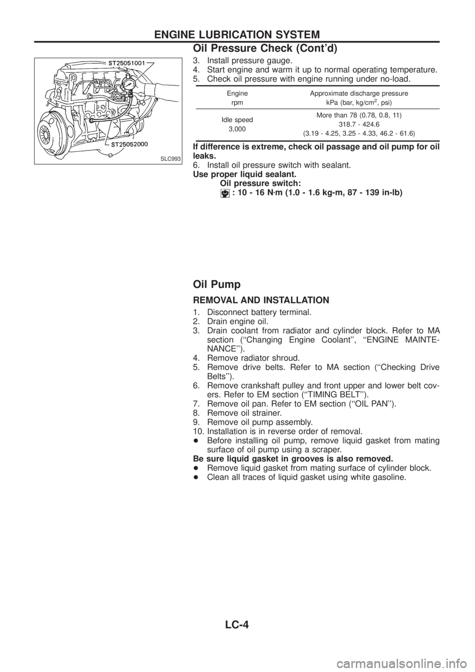
3. Install pressure gauge.
4. Start engine and warm it up to normal operating temperature.
5. Check oil pressure with engine running under no-load.
Engine
rpmApproximate discharge pressure
kPa (bar, kg/cm2, psi)
Idle speed
3,000More than 78 (0.78, 0.8, 11)
318.7 - 424.6
(3.19 - 4.25, 3.25 - 4.33, 46.2 - 61.6)
If difference is extreme, check oil passage and oil pump for oil
leaks.
6. Install oil pressure switch with sealant.
Use proper liquid sealant.
Oil pressure switch:
:10-16Nzm (1.0 - 1.6 kg-m, 87 - 139 in-lb)
Oil Pump
REMOVAL AND INSTALLATION
1. Disconnect battery terminal.
2. Drain engine oil.
3. Drain coolant from radiator and cylinder block. Refer to MA
section (``Changing Engine Coolant'', ``ENGINE MAINTE-
NANCE'').
4. Remove radiator shroud.
5. Remove drive belts. Refer to MA section (``Checking Drive
Belts'').
6. Remove crankshaft pulley and front upper and lower belt cov-
ers. Refer to EM section (``TIMING BELT'').
7. Remove oil pan. Refer to EM section (``OIL PAN'').
8. Remove oil strainer.
9. Remove oil pump assembly.
10. Installation is in reverse order of removal.
+Before installing oil pump, remove liquid gasket from mating
surface of oil pump using a scraper.
Be sure liquid gasket in grooves is also removed.
+Remove liquid gasket from mating surface of cylinder block.
+Clean all traces of liquid gasket using white gasoline.
SLC993
ENGINE LUBRICATION SYSTEM
Oil Pressure Check (Cont'd)
LC-4
Page 977 of 1226
MAINTENANCE
SECTION
MA
CONTENTS
PRECAUTIONS AND PREPARATION............................1
Supplemental Restraint System (SRS) ``AIR
BAG'' and ``SEAT BELT PRE-TENSIONER''...............1
Special Service Tools ..................................................1
PRE-DELIVERY INSPECTION ITEMS............................2
GENERAL MAINTENANCE............................................3
PERIODIC MAINTENANCE............................................4
Engine Oil & Minor Service .........................................4
Engine and Emission Control Service .........................5
Chassis and Body Services.........................................6
Maintenance Under Severe Driving Conditions ..........8
RECOMMENDED FLUIDS AND LUBRICANTS.............9
Fluids and Lubricants ..................................................9
SAE Viscosity Number ..............................................10
Anti-freeze Coolant Mixture Ratio ............................. 11
ENGINE MAINTENANCE..............................................12
Checking Tightening Torque ......................................12
Checking Drive Belt ...................................................12
Changing Engine Oil..................................................13
Changing Engine Oil Filter ........................................14
Changing Engine Coolant..........................................14
Checking Cooling System .........................................16
Checking and Replacing Fuel Filter and Draining
Water .........................................................................16
Checking Fuel Lines ..................................................17
Cleaning and Replacing Air Cleaner Filter ................18
Checking Injection Nozzle .........................................18
Checking Idle Speed .................................................19
Timing Belt Replacement...........................................19
CHASSIS AND BODY MAINTENANCE.......................20
Checking Exhaust System.........................................20
Checking Clutch Fluid Level and Leaks ....................20
Checking Clutch System ...........................................20Checking M/T Oil Level and Leaks ...........................20
Changing M/T Oil.......................................................20
Checking Water Entry ................................................21
Checking Transfer Fluid Level ...................................21
Changing Transfer Fluid ............................................21
Checking Propeller Shaft ...........................................21
Greasing Nipples of Propeller Shafts ........................21
Checking Differential Gear Oil ...................................22
Changing Differential Gear Oil ..................................22
Checking Front Wheel Bearing Grease ....................22
Repacking Front Wheel Bearing and Axle Joint
Grease .......................................................................23
Checking Free-running Hub Grease .........................23
Checking Water Entry in Knuckle Flange..................23
Checking Brake Fluid Level and Leaks.....................23
Checking Brake System ............................................24
Changing Brake Fluid ................................................24
Checking Brake Booster, Vacuum Hoses,
Connections and Check Valve ..................................24
Checking Disc Brake .................................................24
Balancing Wheels ......................................................25
Tire Rotation ..............................................................25
Checking Power Steering Fluid and Lines ................26
Checking Steering Damper .......................................26
Checking Steering Gear Box and Linkage ................26
Lubricating Locks, Hinges and Hood Latches...........27
Checking Seat Belts, Buckles, Retractors,
Anchors and Adjusters...............................................27
Checking Body Corrosion ..........................................28
SERVICE DATA AND SPECIFICATIONS (SDS)..........29
Engine Maintenance ..................................................29
Chassis and Body Maintenance ................................29
MA
Page 990 of 1226

1. Inspect for cracks, fraying, wear or oil adhesion. Replace if
necessary.
The belts should not touch the bottom of the pulley groove.
2. Check drive belt de¯ection by pushing on the belt midway
between pulleys.
Adjust if belt de¯ections exceed the limit.
Unit: mm (in)
Used belt de¯ection
De¯ection of new belt
LimitDe¯ection after
adjustment
Alternator 17 (0.67) 12 - 14 (0.47 - 0.55) 9 - 11 (0.35 - 0.43)
Air conditioner
compressor11 (0.43)7 - 9 (0.28 - 0.35)6 - 8 (0.24 - 0.31)
Power steering oil
pump14 (0.55) 10 - 12 (0.39 - 0.47) 9 - 11 (0.35 - 0.43)
Applied pushing
force98 N (10 kg, 22 lb)
Check drive belt de¯ections when engine is cold.
Changing Engine Oil
WARNING:
+Be careful not to burn yourself, as engine oil is hot.
+Prolonged and repeated contact with used engine oil may
cause skin cancer; try to avoid direct skin contact with
used oil. If skin contact is made, wash thoroughly with
soap or hand cleaner as soon as possible.
1. Warm up engine, and check for oil leakage from engine com-
ponents.
2. Remove oil ®ller cap and drain plug.
3. Drain oil and ®ll with new engine oil.
Oil grade: CCMC PD1 or PD2
Viscosity:
See ``RECOMMENDED FLUIDS AND
LUBRICANTS'', MA-9.
Re®ll oil capacity (approximate):
Without oil ®lter change
6.4!(5-5/8 Imp qt)
With oil ®lter change
5.8!(5-1/8 Imp qt)
CAUTION:
+Be sure to clean and install oil pan drain plug with washer.
Drain plug:
:29-39Nzm (3.0 - 4.0 kg-m, 22 - 29 ft-lb)
+The re®ll capacity changes depending on the oil tempera-
ture and drain time; use these valves as a reference and be
certain to check with the dipstick when changing the oil.
SMA998C
ENGINE MAINTENANCE
Checking Drive Belt (Cont'd)
MA-13
Page 997 of 1226
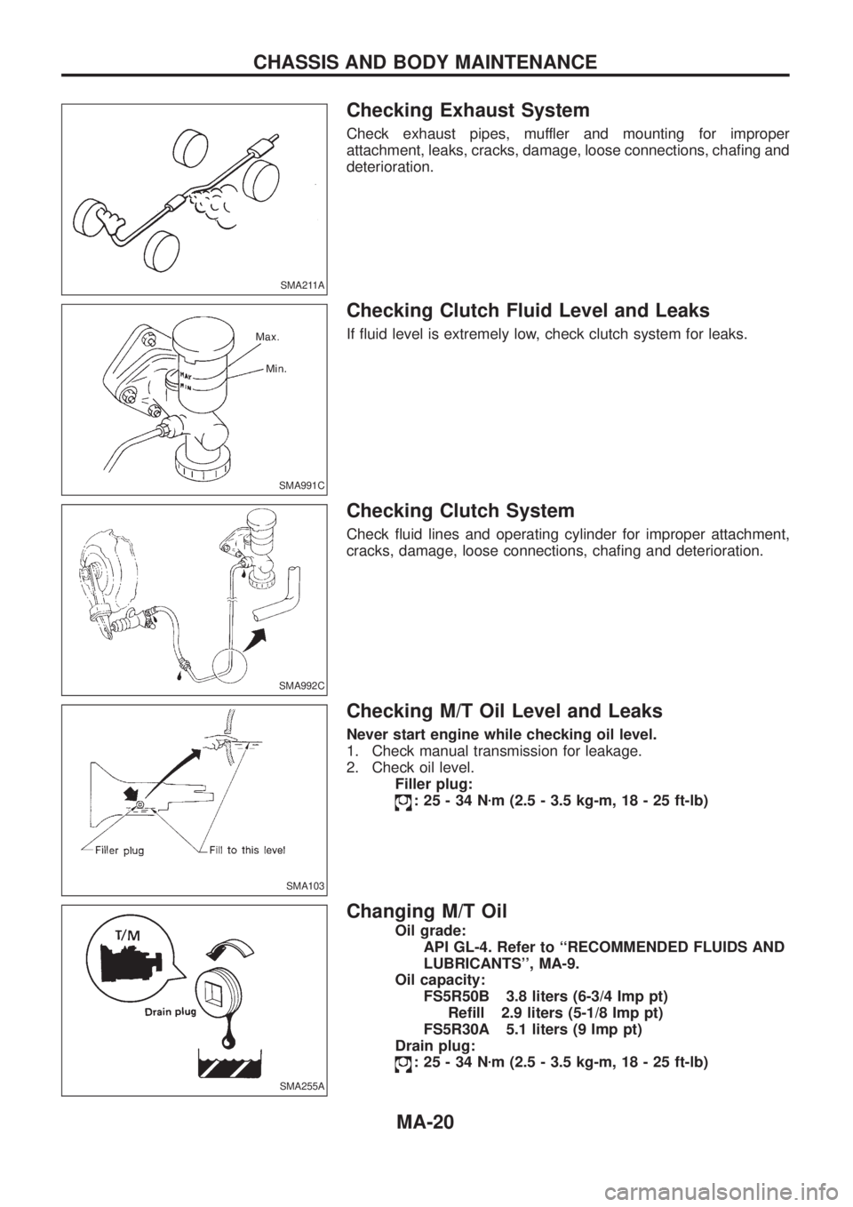
Checking Exhaust System
Check exhaust pipes, muffler and mounting for improper
attachment, leaks, cracks, damage, loose connections, cha®ng and
deterioration.
Checking Clutch Fluid Level and Leaks
If ¯uid level is extremely low, check clutch system for leaks.
Checking Clutch System
Check ¯uid lines and operating cylinder for improper attachment,
cracks, damage, loose connections, cha®ng and deterioration.
Checking M/T Oil Level and Leaks
Never start engine while checking oil level.
1. Check manual transmission for leakage.
2. Check oil level.
Filler plug:
:25-34Nzm (2.5 - 3.5 kg-m, 18 - 25 ft-lb)
Changing M/T Oil
Oil grade:
API GL-4. Refer to ``RECOMMENDED FLUIDS AND
LUBRICANTS'', MA-9.
Oil capacity:
FS5R50B 3.8 liters (6-3/4 Imp pt)
Re®ll 2.9 liters (5-1/8 Imp pt)
FS5R30A 5.1 liters (9 Imp pt)
Drain plug:
:25-34Nzm (2.5 - 3.5 kg-m, 18 - 25 ft-lb)
SMA211A
SMA991C
SMA992C
SMA103
SMA255A
CHASSIS AND BODY MAINTENANCE
MA-20