Page 307 of 1226
EGRC-Solenoid Valve A, B and Throttle Control
Solenoid Valve
SYSTEM DESCRIPTION
Camshaft position sensor (TDC)cEngine speed
ECM
(ECCS-D
control
module)cEGRC-solenoid valve A
Accelerator position sensorcAccelerator positioncEGRC-solenoid valve B
Engine coolant temperature sensorcEngine coolant temperaturecThrottle control solenoid valve
Ignition switchcStart signal
Mass air ¯ow sensor
cAmount of intake air
The ECM receives signals sent from the engine coolant tempera-
ture sensor, crankshaft position sensor (TDC), ignition switch, mass
air ¯ow sensor and accelerator position sensor to determine engine
speed and operating conditions. Based on these signals, the ECM
controls EGR control solenoid valve (A and B) operation and
throttle control solenoid valve operation.
Engine coolant
temperature
ÉC (ÉF)LoadEGRC-solenoid valve
Throttle control
solenoid valveEGR valveThrottle control
valveAmount of EGR
gas
AB
Below 70 (158) AnyOFF
(Closed)OFF
(Closed)OFF
(Closed)Fully closed Fully open Ð
Above 70 (158)Low loadON
(Open)ON
(Open)ON
(Open)Fully open Closed Large
Medium load-1ON
(Open)ON
(Open)OFF
(Closed)Fully open Fully open Medium
Medium load-2ON
(Open)OFF
(Closed)OFF
(Closed)Half open Fully open Small
High loadOFF
(Closed)OFF
(Closed)OFF
(Closed)Fully closed Fully open Ð
COMPONENT DESCRIPTION
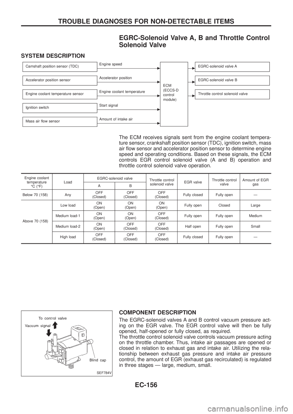
The EGRC-solenoid valves A and B control vacuum pressure act-
ing on the EGR valve. The EGR control valve will then be fully
opened, half-opened or fully closed, as required.
The throttle control solenoid valve controls vacuum pressure acting
on the throttle chamber. Thus, intake air passages are opened or
closed in relation to exhaust gas and intake air. Utilizing the rela-
tionship between exhaust gas pressure and intake air pressure
control, the amount of EGR (exhaust gas recirculated) is regulated
in three stages Ð large, medium, small.
SEF784V
TROUBLE DIAGNOSES FOR NON-DETECTABLE ITEMS
EC-156
Page 320 of 1226
COMPONENT INSPECTION
Accelerator position switch
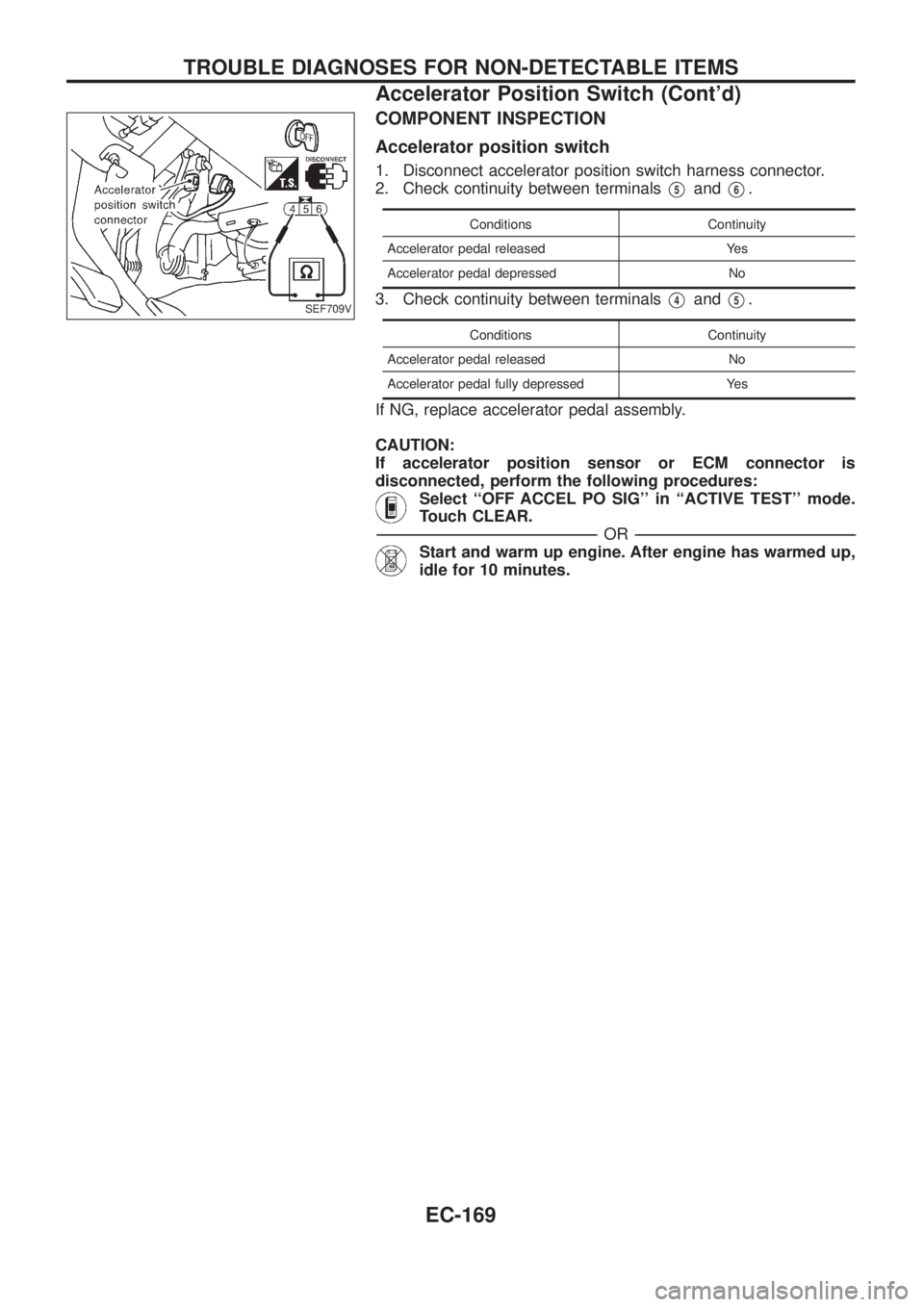
1. Disconnect accelerator position switch harness connector.
2. Check continuity between terminals
V5andV6.
Conditions Continuity
Accelerator pedal released Yes
Accelerator pedal depressed No
3. Check continuity between terminalsV4andV5.
Conditions Continuity
Accelerator pedal released No
Accelerator pedal fully depressed Yes
If NG, replace accelerator pedal assembly.
CAUTION:
If accelerator position sensor or ECM connector is
disconnected, perform the following procedures:
Select ``OFF ACCEL PO SIG'' in ``ACTIVE TEST'' mode.
Touch CLEAR.
-------------------------------------------------------------------------------------------------------------------------------------------------------------------------------------------------------------------------------------------------------OR-------------------------------------------------------------------------------------------------------------------------------------------------------------------------------------------------------------------------------------------------------
Start and warm up engine. After engine has warmed up,
idle for 10 minutes.
SEF709V
TROUBLE DIAGNOSES FOR NON-DETECTABLE ITEMS
Accelerator Position Switch (Cont'd)
EC-169
Page 329 of 1226
Charge Air Cooler Fan Control
SYSTEM DESCRIPTION
Crankshaft position sensor (TDC)cEngine speed
ECM
cCharge air cooler fan relayCharge air temperature sensorcCharge air temperature
Ignition switch
cStart signal
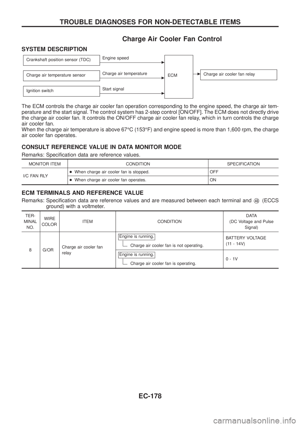
The ECM controls the charge air cooler fan operation corresponding to the engine speed, the charge air tem-
perature and the start signal. The control system has 2-step control [ON/OFF]. The ECM does not directly drive
the charge air cooler fan. It controls the ON/OFF charge air cooler fan relay, which in turn controls the charge
air cooler fan.
When the charge air temperature is above 67ÉC (153ÉF) and engine speed is more than 1,600 rpm, the charge
air cooler fan operates.
CONSULT REFERENCE VALUE IN DATA MONITOR MODE
Remarks: Speci®cation data are reference values.
MONITOR ITEM CONDITION SPECIFICATION
I/C FAN RLY+When charge air cooler fan is stopped. OFF
+When charge air cooler fan operates. ON
ECM TERMINALS AND REFERENCE VALUE
Remarks: Speci®cation data are reference values and are measured between each terminal andV43(ECCS
ground) with a voltmeter.
TER-
MINAL
NO.WIRE
COLORITEM CONDITIONDATA
(DC Voltage and Pulse
Signal)
8 G/ORCharge air cooler fan
relayEngine is running.
Charge air cooler fan is not operating.BATTERY VOLTAGE
(11 - 14V)
Engine is running.
Charge air cooler fan is operating.0-1V
TROUBLE DIAGNOSES FOR NON-DETECTABLE ITEMS
EC-178
Page 331 of 1226
DIAGNOSTIC PROCEDURE
INSPECTION START
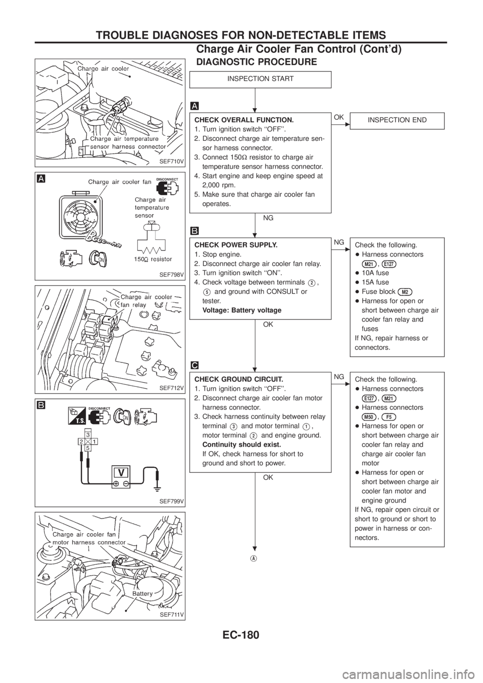
CHECK OVERALL FUNCTION.
1. Turn ignition switch ``OFF''.
2. Disconnect charge air temperature sen-
sor harness connector.
3. Connect 150Wresistor to charge air
temperature sensor harness connector.
4. Start engine and keep engine speed at
2,000 rpm.
5. Make sure that charge air cooler fan
operates.
NG
cOK
INSPECTION END
CHECK POWER SUPPLY.
1. Stop engine.
2. Disconnect charge air cooler fan relay.
3. Turn ignition switch ``ON''.
4. Check voltage between terminals
V2,
V5and ground with CONSULT or
tester.
Voltage: Battery voltage
OK
cNG
Check the following.
+Harness connectors
M21,E127
+10A fuse
+15A fuse
+Fuse block
M2
+Harness for open or
short between charge air
cooler fan relay and
fuses
If NG, repair harness or
connectors.
CHECK GROUND CIRCUIT.
1. Turn ignition switch ``OFF''.
2. Disconnect charge air cooler fan motor
harness connector.
3. Check harness continuity between relay
terminal
V3and motor terminalV1,
motor terminal
V2and engine ground.
Continuity should exist.
If OK, check harness for short to
ground and short to power.
OK
cNG
Check the following.
+Harness connectors
E127,M21
+Harness connectors
M50,F5
+Harness for open or
short between charge air
cooler fan relay and
charge air cooler fan
motor
+Harness for open or
short between charge air
cooler fan motor and
engine ground
If NG, repair open circuit or
short to ground or short to
power in harness or con-
nectors.
jA
SEF710V
SEF798V
SEF712V
SEF799V
SEF711V
.
.
.
.
TROUBLE DIAGNOSES FOR NON-DETECTABLE ITEMS
Charge Air Cooler Fan Control (Cont'd)
EC-180
Page 340 of 1226
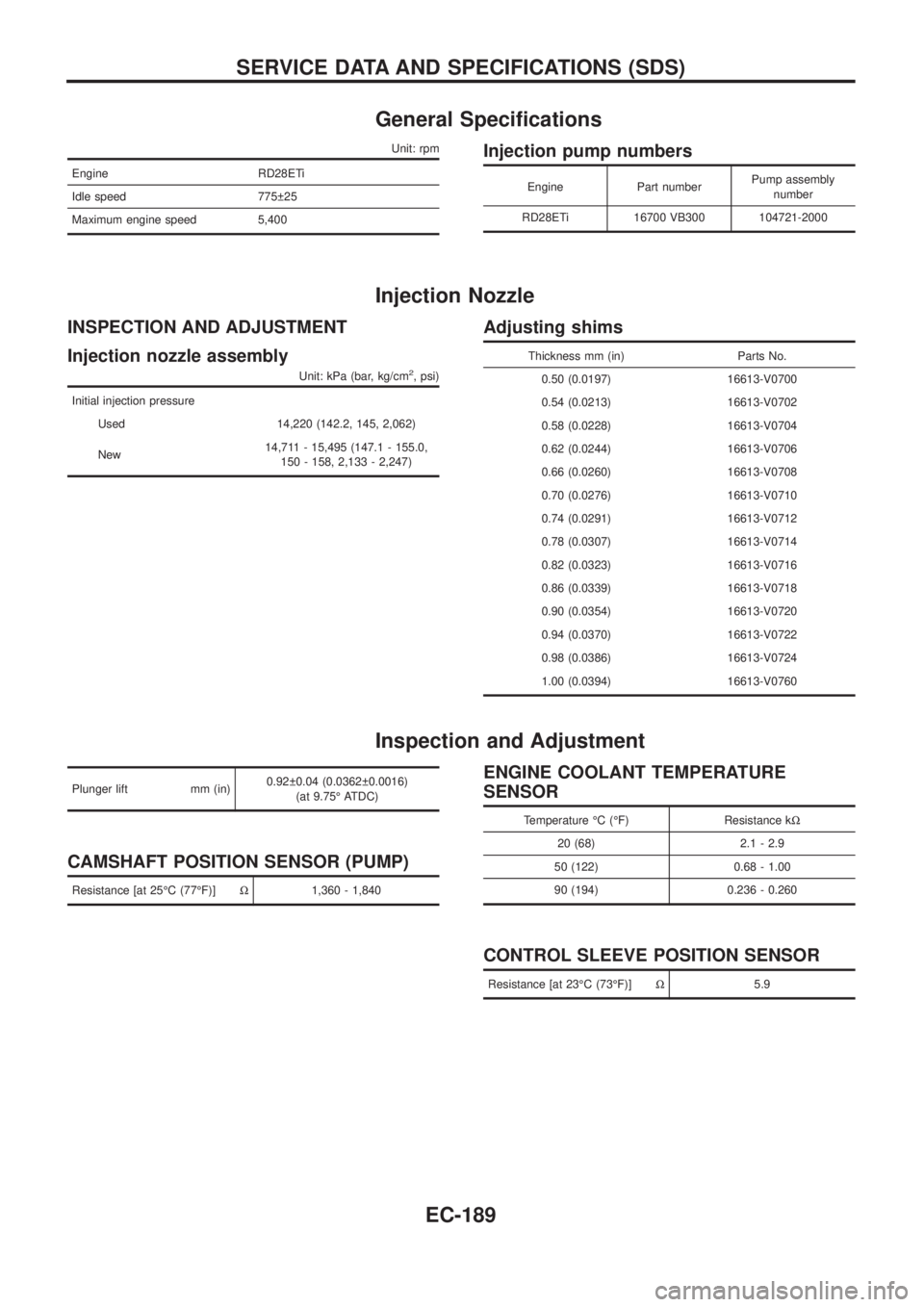
General Speci®cations
Unit: rpm
Engine RD28ETi
Idle speed 775 25
Maximum engine speed 5,400
Injection pump numbers
Engine Part numberPump assembly
number
RD28ETi 16700 VB300 104721-2000
Injection Nozzle
INSPECTION AND ADJUSTMENT
Injection nozzle assembly
Unit: kPa (bar, kg/cm2, psi)
Initial injection pressure
Used 14,220 (142.2, 145, 2,062)
New14,711 - 15,495 (147.1 - 155.0,
150 - 158, 2,133 - 2,247)
Adjusting shims
Thickness mm (in) Parts No.
0.50 (0.0197) 16613-V0700
0.54 (0.0213) 16613-V0702
0.58 (0.0228) 16613-V0704
0.62 (0.0244) 16613-V0706
0.66 (0.0260) 16613-V0708
0.70 (0.0276) 16613-V0710
0.74 (0.0291) 16613-V0712
0.78 (0.0307) 16613-V0714
0.82 (0.0323) 16613-V0716
0.86 (0.0339) 16613-V0718
0.90 (0.0354) 16613-V0720
0.94 (0.0370) 16613-V0722
0.98 (0.0386) 16613-V0724
1.00 (0.0394) 16613-V0760
Inspection and Adjustment
Plunger lift mm (in)0.92 0.04 (0.0362 0.0016)
(at 9.75É ATDC)
CAMSHAFT POSITION SENSOR (PUMP)
Resistance [at 25ÉC (77ÉF)]W1,360 - 1,840
ENGINE COOLANT TEMPERATURE
SENSOR
Temperature ÉC (ÉF) Resistance kW
20 (68) 2.1 - 2.9
50 (122) 0.68 - 1.00
90 (194) 0.236 - 0.260
CONTROL SLEEVE POSITION SENSOR
Resistance [at 23ÉC (73ÉF)]W5.9
SERVICE DATA AND SPECIFICATIONS (SDS)
EC-189
Page 341 of 1226
ADJUSTMENT RESISTOR
Resistance [at 25ÉC (77ÉF)] kW0.2 - 15.0
INJECTION TIMING CONTROL VALVE
Resistance [at 20ÉC (68ÉF)]WApproximately 11
ELECTRIC GOVERNOR
Resistance [at 23ÉC (73ÉF)]W0.68
CRANKSHAFT POSITION SENSOR (TDC)
Resistance [at 25ÉC (77ÉF)] kWApproximately 0.8 - 1.2
GLOW PLUG
Resistance [at 25ÉC (77ÉF)]W0.8
ACCELERATOR POSITION SENSOR
Throttle valve conditionsResistance kW
[at 25ÉC (77ÉF)]
Completely closed Approximately 0.5
Partially open 0.5 - 4
Completely open Approximately 4
FUEL TEMPERATURE SENSOR
Temperature ÉC (ÉF) Resistance kW
þ20 (þ4) 13.67 - 16.37
20 (68) 2.306 - 2.568
60 (140) 0.538 - 0.624
80 (176) 0.289 - 0.344
SERVICE DATA AND SPECIFICATIONS (SDS)
Inspection and Adjustment (Cont'd)
EC-190
Page 346 of 1226
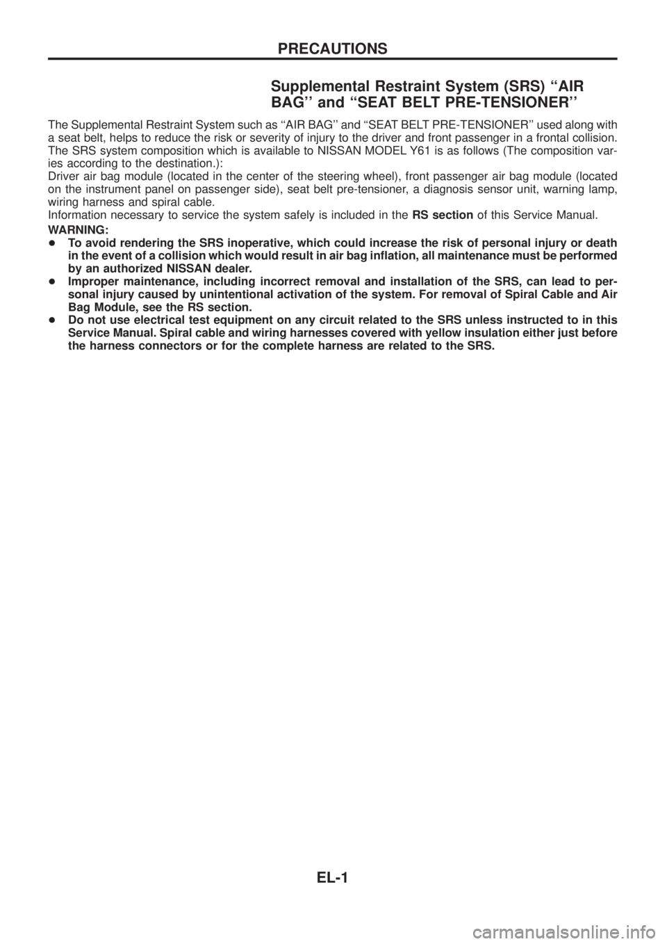
Supplemental Restraint System (SRS) ``AIR
BAG'' and ``SEAT BELT PRE-TENSIONER''
The Supplemental Restraint System such as ``AIR BAG'' and ``SEAT BELT PRE-TENSIONER'' used along with
a seat belt, helps to reduce the risk or severity of injury to the driver and front passenger in a frontal collision.
The SRS system composition which is available to NISSAN MODEL Y61 is as follows (The composition var-
ies according to the destination.):
Driver air bag module (located in the center of the steering wheel), front passenger air bag module (located
on the instrument panel on passenger side), seat belt pre-tensioner, a diagnosis sensor unit, warning lamp,
wiring harness and spiral cable.
Information necessary to service the system safely is included in theRS sectionof this Service Manual.
WARNING:
+To avoid rendering the SRS inoperative, which could increase the risk of personal injury or death
in the event of a collision which would result in air bag in¯ation, all maintenance must be performed
by an authorized NISSAN dealer.
+Improper maintenance, including incorrect removal and installation of the SRS, can lead to per-
sonal injury caused by unintentional activation of the system. For removal of Spiral Cable and Air
Bag Module, see the RS section.
+Do not use electrical test equipment on any circuit related to the SRS unless instructed to in this
Service Manual. Spiral cable and wiring harnesses covered with yellow insulation either just before
the harness connectors or for the complete harness are related to the SRS.
PRECAUTIONS
EL-1
Page 415 of 1226
![NISSAN PATROL 2006 Service Manual System Description
CIRCUIT OPERATION
[Example]
Aiming switch ``0
+When the aiming switch is set to ``0, the motor will not start.
This is because the power terminals are positioned at the non-
con NISSAN PATROL 2006 Service Manual System Description
CIRCUIT OPERATION
[Example]
Aiming switch ``0
+When the aiming switch is set to ``0, the motor will not start.
This is because the power terminals are positioned at the non-
con](/manual-img/5/57368/w960_57368-414.png)
System Description
CIRCUIT OPERATION
[Example]
Aiming switch ``0''
+When the aiming switch is set to ``0'', the motor will not start.
This is because the power terminals are positioned at the non-
conductive section of the sensor's rotary unit.
Aiming switch ``0''®``1''
+When the aiming switch is moved from ``0'' to ``1'', the sensor's
conductive section activates the relay. Power is supplied
through the relay to the motor. The headlamps will then move
in the ``DOWN'' direction.
+The motor continues to rotate while the rotary unit of the sen-
sor moves from point A to point B.
+The power terminals will then be positioned at the nonconduc-
tive section, disconnecting the power to the motor. The motor
will then stop.
Aiming switch ``1''®``0''
+When the aiming switch is moved from ``1'' to ``0'', the sensor's
conductive section activates the relay. Power is supplied
through the relay to the motor. The motor will rotate to move the
headlamps in the ``UP'' direction.
+When the rotary unit of the sensor moves from point B to point
A, the motor will stop.
SEL465M
SEL364P
SEL365P
HEADLAMP Ð Headlamp Aiming Control Ð
EL-70