2006 NISSAN PATROL lock
[x] Cancel search: lockPage 583 of 1226
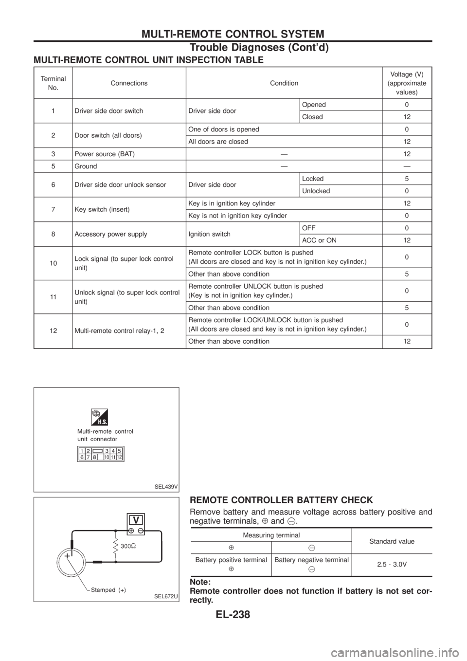
MULTI-REMOTE CONTROL UNIT INSPECTION TABLE
Terminal
No.Connections ConditionVoltage (V)
(approximate
values)
1 Driver side door switch Driver side doorOpened 0
Closed 12
2 Door switch (all doors)One of doors is opened 0
All doors are closed 12
3 Power source (BAT) Ð 12
5 Ground Ð Ð
6 Driver side door unlock sensor Driver side doorLocked 5
Unlocked 0
7 Key switch (insert)Key is in ignition key cylinder 12
Key is not in ignition key cylinder 0
8 Accessory power supply Ignition switchOFF 0
ACC or ON 12
10Lock signal (to super lock control
unit)Remote controller LOCK button is pushed
(All doors are closed and key is not in ignition key cylinder.)0
Other than above condition 5
11Unlock signal (to super lock control
unit)Remote controller UNLOCK button is pushed
(Key is not in ignition key cylinder.)0
Other than above condition 5
12 Multi-remote control relay-1, 2Remote controller LOCK/UNLOCK button is pushed
(All doors are closed and key is not in ignition key cylinder.)0
Other than above condition 12
REMOTE CONTROLLER BATTERY CHECK
Remove battery and measure voltage across battery positive and
negative terminals,Åand@.
Measuring terminal
Standard value
Å@
Battery positive terminal
ÅBattery negative terminal
@2.5 - 3.0V
Note:
Remote controller does not function if battery is not set cor-
rectly.
SEL439V
SEL672U
MULTI-REMOTE CONTROL SYSTEM
Trouble Diagnoses (Cont'd)
EL-238
Page 584 of 1226
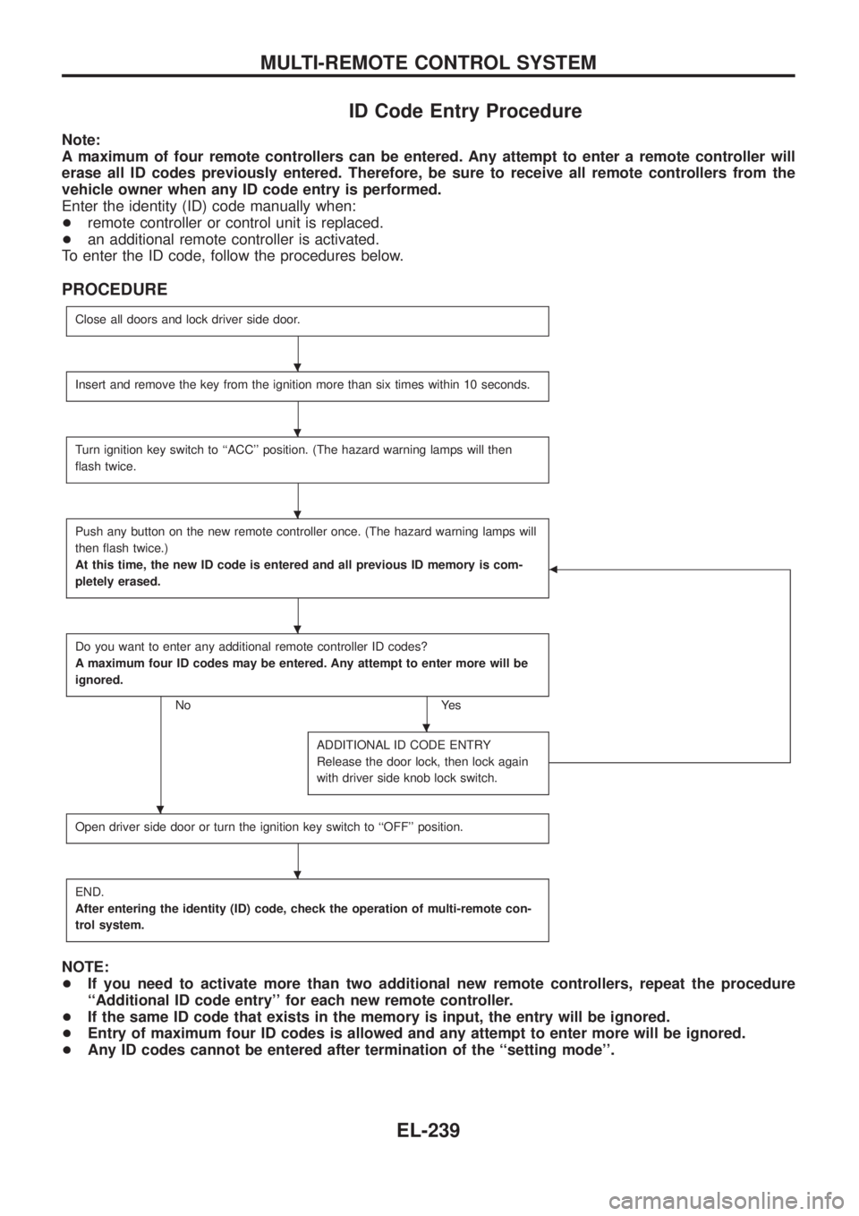
ID Code Entry Procedure
Note:
A maximum of four remote controllers can be entered. Any attempt to enter a remote controller will
erase all ID codes previously entered. Therefore, be sure to receive all remote controllers from the
vehicle owner when any ID code entry is performed.
Enter the identity (ID) code manually when:
+remote controller or control unit is replaced.
+an additional remote controller is activated.
To enter the ID code, follow the procedures below.
PROCEDURE
Close all doors and lock driver side door.
Insert and remove the key from the ignition more than six times within 10 seconds.
Turn ignition key switch to ``ACC'' position. (The hazard warning lamps will then
¯ash twice.
Push any button on the new remote controller once. (The hazard warning lamps will
then ¯ash twice.)
At this time, the new ID code is entered and all previous ID memory is com-
pletely erased.
b
Do you want to enter any additional remote controller ID codes?
A maximum four ID codes may be entered. Any attempt to enter more will be
ignored.
No Yes
ADDITIONAL ID CODE ENTRY
Release the door lock, then lock again
with driver side knob lock switch.
Open driver side door or turn the ignition key switch to ``OFF'' position.
END.
After entering the identity (ID) code, check the operation of multi-remote con-
trol system.
NOTE:
+If you need to activate more than two additional new remote controllers, repeat the procedure
``Additional ID code entry'' for each new remote controller.
+If the same ID code that exists in the memory is input, the entry will be ignored.
+Entry of maximum four ID codes is allowed and any attempt to enter more will be ignored.
+Any ID codes cannot be entered after termination of the ``setting mode''.
.
.
.
.
.
.
.
MULTI-REMOTE CONTROL SYSTEM
EL-239
Page 588 of 1226
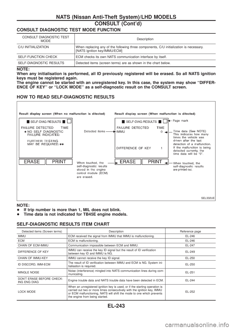
CONSULT DIAGNOSTIC TEST MODE FUNCTION
CONSULT DIAGNOSTIC TEST
MODEDescription
C/U INITIALIZATION When replacing any of the following three components, C/U initialization is necessary.
[NATS ignition key/IMMU/ECM]
SELF-FUNCTION CHECK ECM checks its own NATS communication interface by itself.
SELF-DIAGNOSTIC RESULTS Detected items (screen terms) are as shown in the chart below.
NOTE:
When any initialisation is performed, all ID previously registered will be erased. So all NATS ignition
keys must be registered again.
The engine cannot be started with an unregistered key. In this case, the system may show ``DIFFER-
ENCE OF KEY'' or ``LOCK MODE'' as a self-diagnostic result on the CONSULT screen.
HOW TO READ SELF-DIAGNOSTIC RESULTS
NOTE:
+If trip number is more than 1, MIL does not blink.
+Time data is not indicated for TB45E engine models.
SELF-DIAGNOSTIC RESULTS ITEM CHART
Detected items (Screen terms) Description Reference page
IMMU ECM received the signal from IMMU that IMMU is malfunctioning. EL-246
ECM ECM is malfunctioning. EL-246
CHAIN OF ECM-IMMU Communication impossible between ECM and IMMU. EL-247
DIFFERENCE OF KEYIMMU can receive the key ID signal but the result of ID veri®cation
between key ID and IMMU is NG.EL-249
CHAIN OF IMMU-KEY IMMU cannot receive the key ID signal. EL-250
ID DISCORD, IMM-ECMThe result of ID veri®cation between IMMU and ECM is NG. System ini-
tialisation is required.EL-250
MINGLE NOISENoise (interference) mingled into NATS communication lines during com-
municating.EL-251
DON'T ERASE BEFORE CHECK-
ING ENG DIAGEngine trouble data and NATS trouble data have been detected in ECM. EL-244
LOCK MODEWhen an unregistered ignition key is used, or if the starting operation is
carried out two or more times consecutively with the ignition key, IMMU
or ECM malfunctioning, NATS will shift the mode to one which prevents
the engine from being started.EL-252
SEL332UE
NATS (Nissan Anti-Theft System)/LHD MODELS
CONSULT (Cont'd)
EL-243
Page 590 of 1226
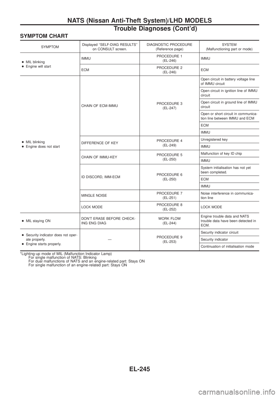
SYMPTOM CHART
SYMPTOMDisplayed ``SELF-DIAG RESULTS''
on CONSULT screen.DIAGNOSTIC PROCEDURE
(Reference page)SYSTEM
(Malfunctioning part or mode)
+MIL blinking
+Engine will startIMMUPROCEDURE 1
(EL-246)IMMU
ECMPROCEDURE 2
(EL-246)ECM
+MIL blinking
+Engine does not startCHAIN OF ECM-IMMUPROCEDURE 3
(EL-247)Open circuit in battery voltage line
of IMMU circuit
Open circuit in ignition line of IMMU
circuit
Open circuit in ground line of IMMU
circuit
Open or short circuit in communica-
tion line between IMMU and ECM
ECM
IMMU
DIFFERENCE OF KEYPROCEDURE 4
(EL-249)Unregistered key
IMMU
CHAIN OF IMMU-KEYPROCEDURE 5
(EL-250)Malfunction of key ID chip
IMMU
ID DISCORD, IMM-ECMPROCEDURE 6
(EL-250)System initialisation has not yet
been completed.
ECM
IMMU
MINGLE NOISEPROCEDURE 7
(EL-251)Noise interference in communica-
tion line
LOCK MODEPROCEDURE 8
(EL-252)LOCK MODE
+MIL staying ONDON'T ERASE BEFORE CHECK-
ING ENG DIAGWORK FLOW
(EL-244)Engine trouble data and NATS
trouble data have been detected in
ECM.
+Security indicator does not oper-
ate properly.
+Engine starts properly.ÐPROCEDURE 9
(EL-253)Security indicator circuit
Security indicator
Continuation of initialisation mode
*Lighting-up mode of MIL (Malfunction Indicator Lamp)
For single malfunction of NATS: Blinking
For dual malfunctions of NATS and an engine-related part: Stays ON
For single malfunction of an engine-related part: Stays ON
NATS (Nissan Anti-Theft System)/LHD MODELS
Trouble Diagnoses (Cont'd)
EL-245
Page 592 of 1226
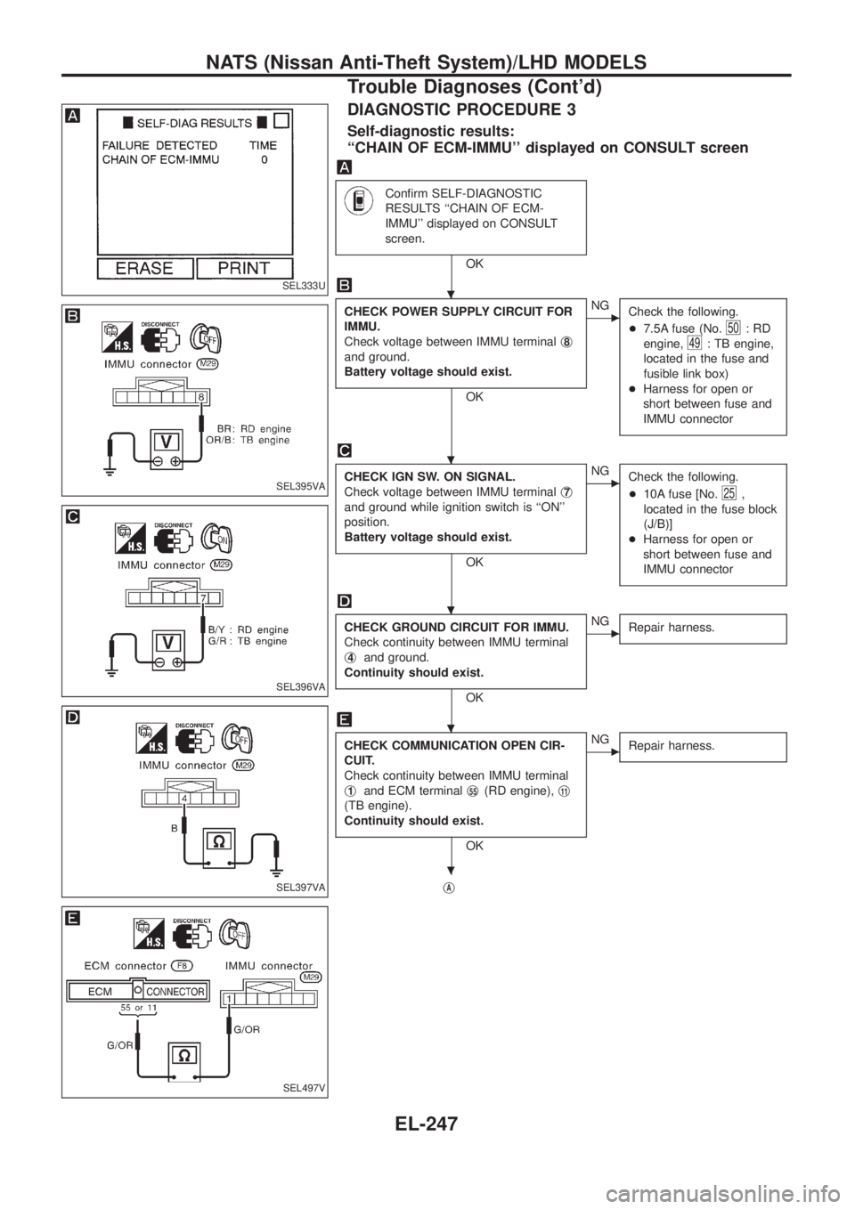
DIAGNOSTIC PROCEDURE 3
Self-diagnostic results:
``CHAIN OF ECM-IMMU'' displayed on CONSULT screen
Con®rm SELF-DIAGNOSTIC
RESULTS ``CHAIN OF ECM-
IMMU'' displayed on CONSULT
screen.
OK
CHECK POWER SUPPLY CIRCUIT FOR
IMMU.
Check voltage between IMMU terminalj
8
and ground.
Battery voltage should exist.
OK
cNG
Check the following.
+7.5A fuse (No.
50:RD
engine,
49: TB engine,
located in the fuse and
fusible link box)
+Harness for open or
short between fuse and
IMMU connector
CHECK IGN SW. ON SIGNAL.
Check voltage between IMMU terminalj
7
and ground while ignition switch is ``ON''
position.
Battery voltage should exist.
OK
cNG
Check the following.
+10A fuse [No.
25,
located in the fuse block
(J/B)]
+Harness for open or
short between fuse and
IMMU connector
CHECK GROUND CIRCUIT FOR IMMU.
Check continuity between IMMU terminal
j
4and ground.
Continuity should exist.
OK
cNG
Repair harness.
CHECK COMMUNICATION OPEN CIR-
CUIT.
Check continuity between IMMU terminal
j
1and ECM terminalj55(RD engine),j11
(TB engine).
Continuity should exist.
OK
cNG
Repair harness.
jA
SEL333U
SEL395VA
SEL396VA
SEL397VA
SEL497V
.
.
.
.
.
NATS (Nissan Anti-Theft System)/LHD MODELS
Trouble Diagnoses (Cont'd)
EL-247
Page 597 of 1226
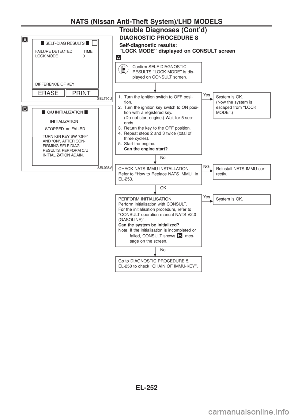
DIAGNOSTIC PROCEDURE 8
Self-diagnostic results:
``LOCK MODE'' displayed on CONSULT screen
Con®rm SELF-DIAGNOSTIC
RESULTS ``LOCK MODE'' is dis-
played on CONSULT screen.
1. Turn the ignition switch to OFF posi-
tion.
2. Turn the ignition key switch to ON posi-
tion with a registered key.
(Do not start engine.) Wait for 5 sec-
onds.
3. Return the key to the OFF position.
4. Repeat steps 2 and 3 twice (total of
three cycles).
5. Start the engine.
Can the engine start?
No
cYe s
System is OK.
(Now the system is
escaped from ``LOCK
MODE''.)
CHECK NATS IMMU INSTALLATION.
Refer to ``How to Replace NATS IMMU'' in
EL-253.
OK
cNG
Reinstall NATS IMMU cor-
rectly.
PERFORM INITIALISATION.
Perform initialisation with CONSULT.
For the initialisation procedure, refer to
``CONSULT operation manual NATS V2.0
(GASOLINE)''.
Can the system be initialized?
Note: If the initialisation is incompleted or
failed, CONSULT shows
mes-
sage on the screen.
No
cYe s
System is OK.
Go to DIAGNOSTIC PROCEDURE 5,
EL-250 to check ``CHAIN OF IMMU-KEY''.
SEL790U
SEL038V
.
.
.
.
NATS (Nissan Anti-Theft System)/LHD MODELS
Trouble Diagnoses (Cont'd)
EL-252
Page 598 of 1226
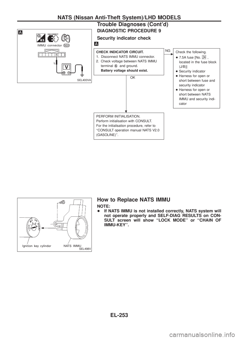
DIAGNOSTIC PROCEDURE 9
Security indicator check
CHECK INDICATOR CIRCUIT.
1. Disconnect NATS IMMU connector.
2. Check voltage between NATS IMMU
terminalj
6and ground.
Battery voltage should exist.
OK
cNG
Check the following.
+7.5A fuse [No.
24,
located in the fuse block
(J/B)]
+Security indicator
+Harness for open or
short between fuse and
security indicator
+Harness for open or
short between NATS
IMMU and security indi-
cator
PERFORM INITIALISATION.
Perform initialisation with CONSULT.
For the initialisation procedure, refer to
``CONSULT operation manual NATS V2.0
(GASOLINE)''.
How to Replace NATS IMMU
NOTE:
+If NATS IMMU is not installed correctly, NATS system will
not operate properly and SELF-DIAG RESULTS on CON-
SULT screen will show ``LOCK MODE'' or ``CHAIN OF
IMMU-KEY''.
SEL400VA
SEL498V
.
NATS (Nissan Anti-Theft System)/LHD MODELS
Trouble Diagnoses (Cont'd)
EL-253
Page 603 of 1226
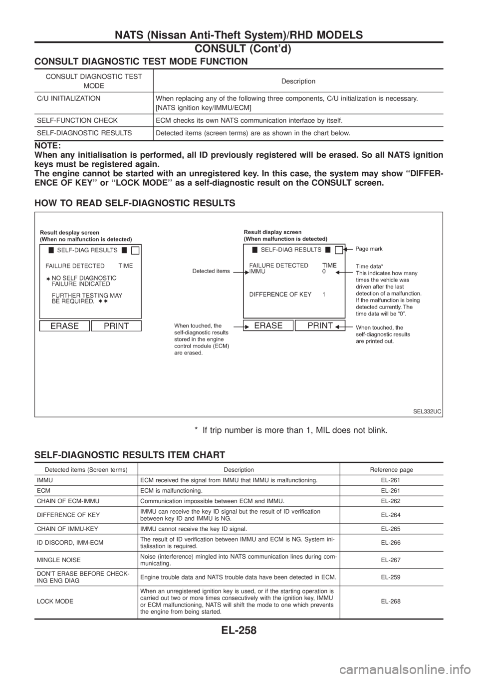
CONSULT DIAGNOSTIC TEST MODE FUNCTION
CONSULT DIAGNOSTIC TEST
MODEDescription
C/U INITIALIZATION When replacing any of the following three components, C/U initialization is necessary.
[NATS ignition key/IMMU/ECM]
SELF-FUNCTION CHECK ECM checks its own NATS communication interface by itself.
SELF-DIAGNOSTIC RESULTS Detected items (screen terms) are as shown in the chart below.
NOTE:
When any initialisation is performed, all ID previously registered will be erased. So all NATS ignition
keys must be registered again.
The engine cannot be started with an unregistered key. In this case, the system may show ``DIFFER-
ENCE OF KEY'' or ``LOCK MODE'' as a self-diagnostic result on the CONSULT screen.
HOW TO READ SELF-DIAGNOSTIC RESULTS
* If trip number is more than 1, MIL does not blink.
SELF-DIAGNOSTIC RESULTS ITEM CHART
Detected items (Screen terms) Description Reference page
IMMU ECM received the signal from IMMU that IMMU is malfunctioning. EL-261
ECM ECM is malfunctioning. EL-261
CHAIN OF ECM-IMMU Communication impossible between ECM and IMMU. EL-262
DIFFERENCE OF KEYIMMU can receive the key ID signal but the result of ID veri®cation
between key ID and IMMU is NG.EL-264
CHAIN OF IMMU-KEY IMMU cannot receive the key ID signal. EL-265
ID DISCORD, IMM-ECMThe result of ID veri®cation between IMMU and ECM is NG. System ini-
tialisation is required.EL-266
MINGLE NOISENoise (interference) mingled into NATS communication lines during com-
municating.EL-267
DON'T ERASE BEFORE CHECK-
ING ENG DIAGEngine trouble data and NATS trouble data have been detected in ECM. EL-259
LOCK MODEWhen an unregistered ignition key is used, or if the starting operation is
carried out two or more times consecutively with the ignition key, IMMU
or ECM malfunctioning, NATS will shift the mode to one which prevents
the engine from being started.EL-268
SEL332UC
NATS (Nissan Anti-Theft System)/RHD MODELS
CONSULT (Cont'd)
EL-258