2006 NISSAN PATROL Instructions
[x] Cancel search: InstructionsPage 120 of 1226
REMOVAL
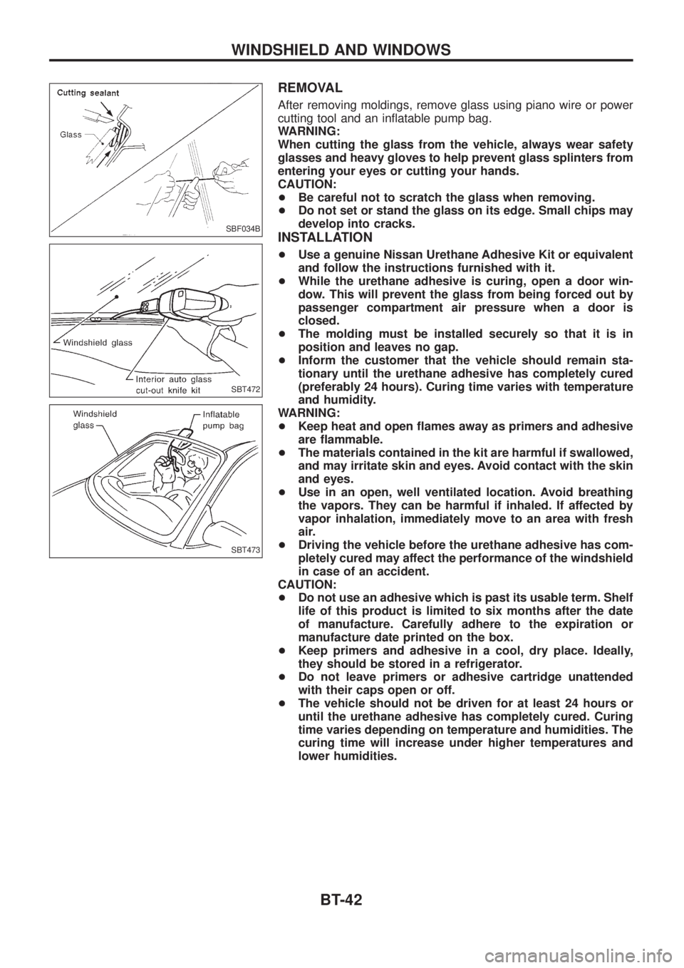
After removing moldings, remove glass using piano wire or power
cutting tool and an in¯atable pump bag.
WARNING:
When cutting the glass from the vehicle, always wear safety
glasses and heavy gloves to help prevent glass splinters from
entering your eyes or cutting your hands.
CAUTION:
+Be careful not to scratch the glass when removing.
+Do not set or stand the glass on its edge. Small chips may
develop into cracks.
INSTALLATION
+Use a genuine Nissan Urethane Adhesive Kit or equivalent
and follow the instructions furnished with it.
+While the urethane adhesive is curing, open a door win-
dow. This will prevent the glass from being forced out by
passenger compartment air pressure when a door is
closed.
+The molding must be installed securely so that it is in
position and leaves no gap.
+Inform the customer that the vehicle should remain sta-
tionary until the urethane adhesive has completely cured
(preferably 24 hours). Curing time varies with temperature
and humidity.
WARNING:
+Keep heat and open ¯ames away as primers and adhesive
are ¯ammable.
+The materials contained in the kit are harmful if swallowed,
and may irritate skin and eyes. Avoid contact with the skin
and eyes.
+Use in an open, well ventilated location. Avoid breathing
the vapors. They can be harmful if inhaled. If affected by
vapor inhalation, immediately move to an area with fresh
air.
+Driving the vehicle before the urethane adhesive has com-
pletely cured may affect the performance of the windshield
in case of an accident.
CAUTION:
+Do not use an adhesive which is past its usable term. Shelf
life of this product is limited to six months after the date
of manufacture. Carefully adhere to the expiration or
manufacture date printed on the box.
+Keep primers and adhesive in a cool, dry place. Ideally,
they should be stored in a refrigerator.
+Do not leave primers or adhesive cartridge unattended
with their caps open or off.
+The vehicle should not be driven for at least 24 hours or
until the urethane adhesive has completely cured. Curing
time varies depending on temperature and humidities. The
curing time will increase under higher temperatures and
lower humidities.
SBF034B
SBT472
SBT473
WINDSHIELD AND WINDOWS
BT-42
Page 395 of 1226
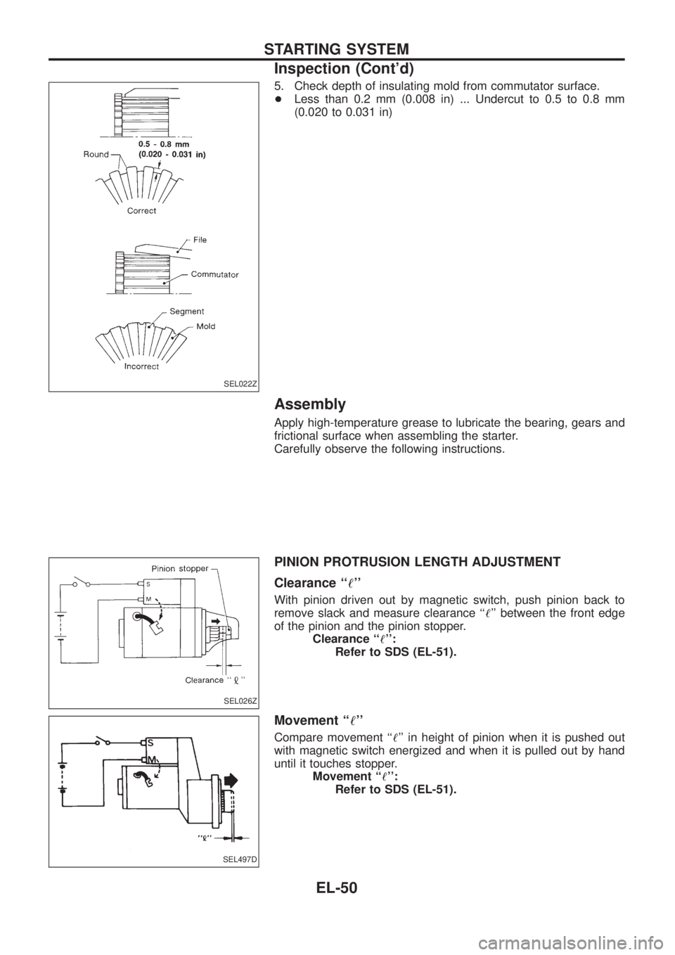
5. Check depth of insulating mold from commutator surface.
+Less than 0.2 mm (0.008 in) ... Undercut to 0.5 to 0.8 mm
(0.020 to 0.031 in)
Assembly
Apply high-temperature grease to lubricate the bearing, gears and
frictional surface when assembling the starter.
Carefully observe the following instructions.
PINION PROTRUSION LENGTH ADJUSTMENT
Clearance ``!''
With pinion driven out by magnetic switch, push pinion back to
remove slack and measure clearance ``!'' between the front edge
of the pinion and the pinion stopper.
Clearance ``!'':
Refer to SDS (EL-51).
Movement ``!''
Compare movement ``!'' in height of pinion when it is pushed out
with magnetic switch energized and when it is pulled out by hand
until it touches stopper.
Movement ``!'':
Refer to SDS (EL-51).
SEL022Z
SEL026Z
SEL497D
STARTING SYSTEM
Inspection (Cont'd)
EL-50
Page 777 of 1226

Precautions for Three Way Catalyst
(If so equipped)
If a large amount of unburned fuel ¯ows into the catalyst, the cata-
lyst temperature will be excessively high. To prevent this, follow the
instructions below:
+Use unleaded gasoline only. Leaded gasoline will seriously
damage the three way catalyst.
+When checking for ignition spark or measuring engine
compression, make tests quickly and only when necessary.
+Do not run engine when the fuel tank level is low, otherwise the
engine may mis®re causing damage to the catalyst.
Do not place the vehicle on ¯ammable material. Keep ¯ammable
material off the exhaust pipe and the three way catalyst.
Precautions for Engine Oils
Prolonged and repeated contact with used engine oil may cause
skin cancer. Try to avoid direct skin contact with used oil.
If skin contact is made, wash thoroughly with soap or hand cleaner
as soon as possible.
HEALTH PROTECTION PRECAUTIONS
+Avoid prolonged and repeated contact with oils, particularly
used engine oils.
+Wear protective clothing, including impervious gloves where
practicable.
+Do not put oily rags in pockets.
+Avoid contaminating clothes, particularly underpants, with oil.
+Heavily soiled clothing and oil-impregnated footwear should not
be worn. Overalls must be cleaned regularly.
+First Aid treatment should be obtained immediately for open
cuts and wounds.
+Use barrier creams, applying them before each work period, to
help the removal of oil from the skin.
+Wash with soap and water to ensure all oil is removed (skin
cleansers and nail brushes will help). Preparations containing
lanolin replace the natural skin oils which have been removed.
+Do not use gasoline, kerosine, diesel fuel, gas oil, thinners or
solvents for cleaning skin.
+If skin disorders develop, obtain medical advice without delay.
+Where practicable, degrease components prior to handling.
+Where there is a risk of eye contact, eye protection should be
worn, for example, chemical goggles or face shields; in addition
an eye wash facility should be provided.
ENVIRONMENTAL PROTECTION PRECAUTIONS
Burning used engine oil in small space heaters or boilers can be
recommended only for units of approved design. The heating sys-
tem must meet the requirements of HM Inspectorate of Pollution for
small burners of less than 0.4 MW. If in doubt check with the
appropriate local authority and/or manufacturer of the approved
appliance.
PRECAUTIONS
GI-4
Page 778 of 1226
Dispose of used oil and used oil ®lters through authorized waste
disposal contractors to licensed waste disposal sites, or to the
waste oil reclamation trade. If in doubt, contact the local authority
for advice on disposal facilities.
It is illegal to pour used oil on to the ground, down sewers or drains,
or into water courses.
The regulations concerning the pollution of the environment
will vary from country to country.
Precautions for Fuel
GASOLINE ENGINE:
Three way catalyst equipped models ... unleaded gasoline of at
least 91 octane (RON)
CAUTION:
Do not use leaded gasoline. Using leaded gasoline will dam-
age the three way catalyst.
Except for the above models ... unleaded or leaded gasoline of
above 88 octane (RON)
Use unleaded fuel if instructed on the fuel ®ller lid.
DIESEL ENGINE*:
Diesel fuel of above 45 cetane for TD42 engine and above 50 cet-
ane for RD28ET engine
* If two types of diesel fuel are available, use summer or winter
fuel properly according to the following temperature conditions.
+Above þ7ÉC (20ÉF) ... Summer type diesel fuel.
+Below þ7ÉC (20ÉF) ... Winter type diesel fuel.
CAUTION:
+Do not use home heating oil, gasoline, or other alternate
fuels in your diesel engine. The use of those can cause
engine damage.
+Do not use summer fuel at temperature below þ7ÉC (20ÉF).
The cold temperature will cause wax to form in the fuel. As
a result, it may prevent the engine from running smoothly.
+Do not add gasoline or other alternate fuels to diesel fuel.
Precautions for Air Conditioning
Use an approved refrigerant recovery unit any time the air condi-
tioning system must be discharged. Refer to HA section (``HFC-
134a (R-134a) Service Procedure'', ``SERVICE PROCEDURES'')
for speci®c instructions.
PRECAUTIONS
Precautions for Engine Oils (Cont'd)
GI-5
Page 780 of 1226
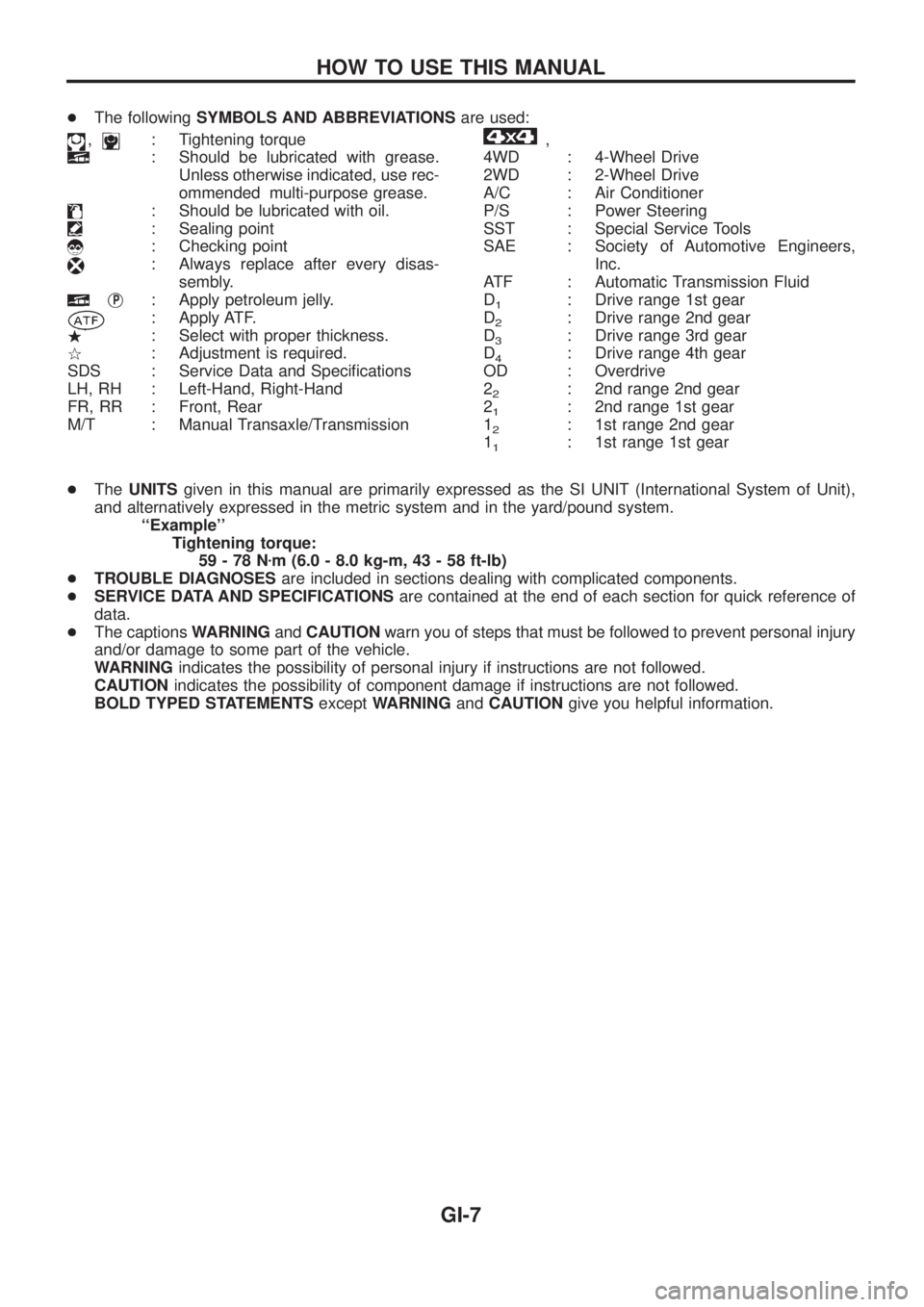
+The followingSYMBOLS AND ABBREVIATIONSare used:
,: Tightening torque
: Should be lubricated with grease.
Unless otherwise indicated, use rec-
ommended multi-purpose grease.
: Should be lubricated with oil.
: Sealing point
: Checking point
: Always replace after every disas-
sembly.
jP: Apply petroleum jelly.
: Apply ATF.
.: Select with proper thickness.
>: Adjustment is required.
SDS : Service Data and Speci®cations
LH, RH : Left-Hand, Right-Hand
FR, RR : Front, Rear
M/T : Manual Transaxle/Transmission
,
4WD : 4-Wheel Drive
2WD : 2-Wheel Drive
A/C : Air Conditioner
P/S : Power Steering
SST : Special Service Tools
SAE : Society of Automotive Engineers,
Inc.
ATF : Automatic Transmission Fluid
D
1: Drive range 1st gear
D
2: Drive range 2nd gear
D
3: Drive range 3rd gear
D
4: Drive range 4th gear
OD : Overdrive
2
2: 2nd range 2nd gear
2
1: 2nd range 1st gear
1
2: 1st range 2nd gear
1
1: 1st range 1st gear
+TheUNITSgiven in this manual are primarily expressed as the SI UNIT (International System of Unit),
and alternatively expressed in the metric system and in the yard/pound system.
``Example''
Tightening torque:
59-78Nzm (6.0 - 8.0 kg-m, 43 - 58 ft-lb)
+TROUBLE DIAGNOSESare included in sections dealing with complicated components.
+SERVICE DATA AND SPECIFICATIONSare contained at the end of each section for quick reference of
data.
+The captionsWARNINGandCAUTIONwarn you of steps that must be followed to prevent personal injury
and/or damage to some part of the vehicle.
WARNINGindicates the possibility of personal injury if instructions are not followed.
CAUTIONindicates the possibility of component damage if instructions are not followed.
BOLD TYPED STATEMENTSexceptWARNINGandCAUTIONgive you helpful information.
HOW TO USE THIS MANUAL
GI-7
Page 803 of 1226
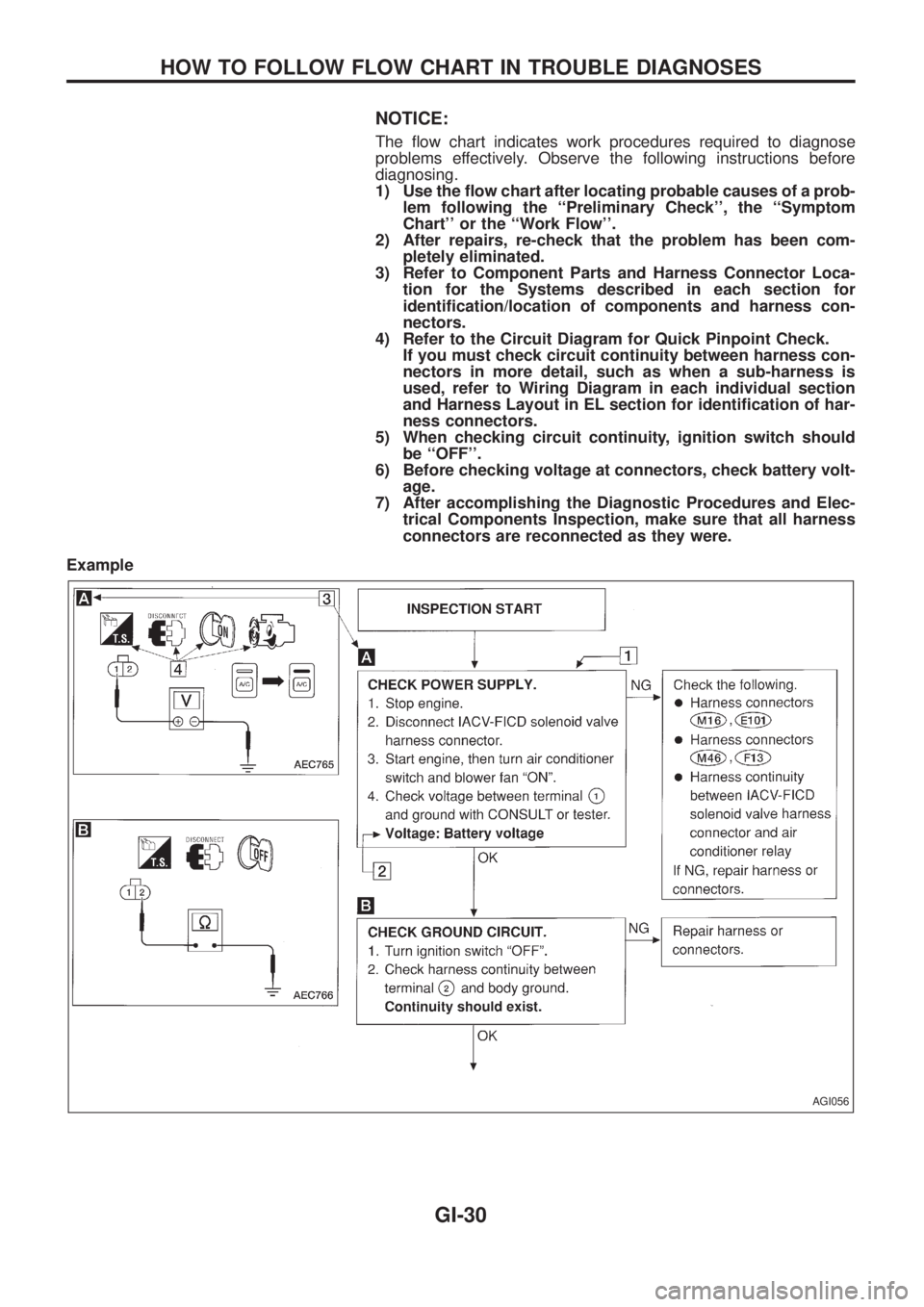
NOTICE:
The ¯ow chart indicates work procedures required to diagnose
problems effectively. Observe the following instructions before
diagnosing.
1) Use the ¯ow chart after locating probable causes of a prob-
lem following the ``Preliminary Check'', the ``Symptom
Chart'' or the ``Work Flow''.
2) After repairs, re-check that the problem has been com-
pletely eliminated.
3) Refer to Component Parts and Harness Connector Loca-
tion for the Systems described in each section for
identi®cation/location of components and harness con-
nectors.
4) Refer to the Circuit Diagram for Quick Pinpoint Check.
If you must check circuit continuity between harness con-
nectors in more detail, such as when a sub-harness is
used, refer to Wiring Diagram in each individual section
and Harness Layout in EL section for identi®cation of har-
ness connectors.
5) When checking circuit continuity, ignition switch should
be ``OFF''.
6) Before checking voltage at connectors, check battery volt-
age.
7) After accomplishing the Diagnostic Procedures and Elec-
trical Components Inspection, make sure that all harness
connectors are reconnected as they were.
Example
AGI056
HOW TO FOLLOW FLOW CHART IN TROUBLE DIAGNOSES
GI-30
Page 830 of 1226
Precautions for Service Equipment
RECOVERY/RECYCLING EQUIPMENT
Follow the manufacturer's instructions for machine operation and
machine maintenance. Never introduce any refrigerant other than
that speci®ed into the machine.
ELECTRONIC LEAK DETECTOR
Follow the manufacture's instructions for tester operation and tester
maintenance.
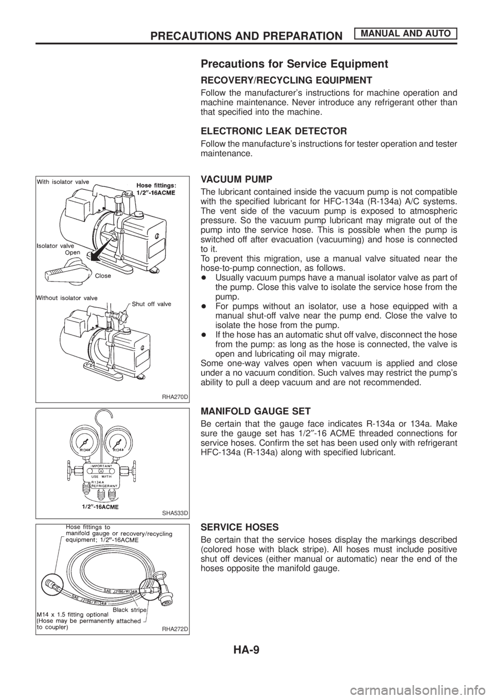
VACUUM PUMP
The lubricant contained inside the vacuum pump is not compatible
with the speci®ed lubricant for HFC-134a (R-134a) A/C systems.
The vent side of the vacuum pump is exposed to atmospheric
pressure. So the vacuum pump lubricant may migrate out of the
pump into the service hose. This is possible when the pump is
switched off after evacuation (vacuuming) and hose is connected
to it.
To prevent this migration, use a manual valve situated near the
hose-to-pump connection, as follows.
+Usually vacuum pumps have a manual isolator valve as part of
the pump. Close this valve to isolate the service hose from the
pump.
+For pumps without an isolator, use a hose equipped with a
manual shut-off valve near the pump end. Close the valve to
isolate the hose from the pump.
+If the hose has an automatic shut off valve, disconnect the hose
from the pump: as long as the hose is connected, the valve is
open and lubricating oil may migrate.
Some one-way valves open when vacuum is applied and close
under a no vacuum condition. Such valves may restrict the pump's
ability to pull a deep vacuum and are not recommended.
MANIFOLD GAUGE SET
Be certain that the gauge face indicates R-134a or 134a. Make
sure the gauge set has 1/2²-16 ACME threaded connections for
service hoses. Con®rm the set has been used only with refrigerant
HFC-134a (R-134a) along with speci®ed lubricant.
SERVICE HOSES
Be certain that the service hoses display the markings described
(colored hose with black stripe). All hoses must include positive
shut off devices (either manual or automatic) near the end of the
hoses opposite the manifold gauge.
RHA270D
SHA533D
RHA272D
PRECAUTIONS AND PREPARATIONMANUAL AND AUTO
HA-9
Page 940 of 1226
Checking Refrigerant Leaks
PRELIMINARY CHECK
Perform a visual inspection of all refrigeration parts, ®ttings, hoses,
and components for signs of A/C lubricant leakage, damage and
corrosion.
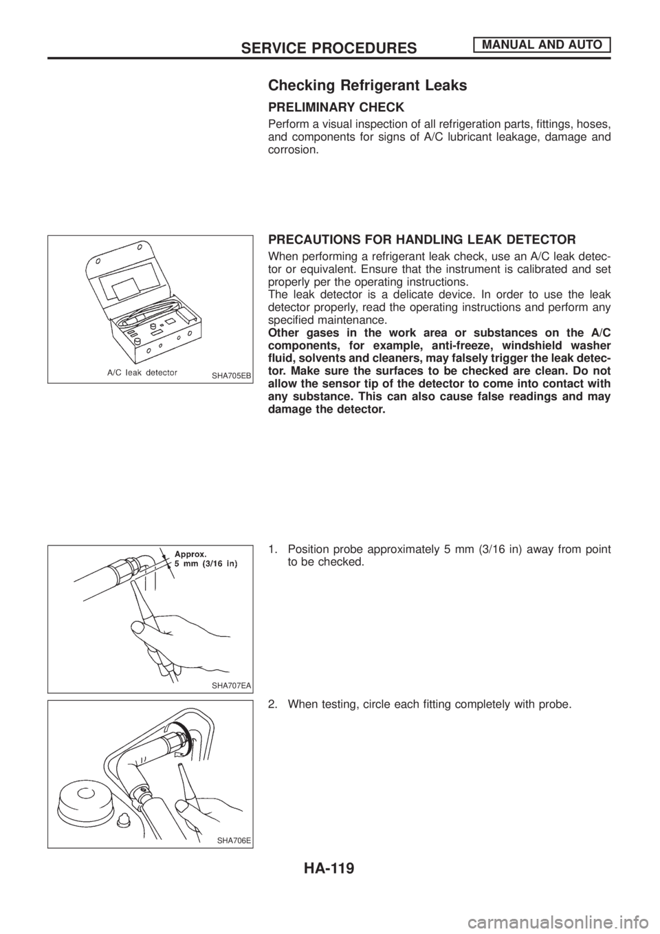
PRECAUTIONS FOR HANDLING LEAK DETECTOR
When performing a refrigerant leak check, use an A/C leak detec-
tor or equivalent. Ensure that the instrument is calibrated and set
properly per the operating instructions.
The leak detector is a delicate device. In order to use the leak
detector properly, read the operating instructions and perform any
speci®ed maintenance.
Other gases in the work area or substances on the A/C
components, for example, anti-freeze, windshield washer
¯uid, solvents and cleaners, may falsely trigger the leak detec-
tor. Make sure the surfaces to be checked are clean. Do not
allow the sensor tip of the detector to come into contact with
any substance. This can also cause false readings and may
damage the detector.
1. Position probe approximately 5 mm (3/16 in) away from point
to be checked.
2. When testing, circle each ®tting completely with probe.
SHA705EB
SHA707EA
SHA706E
SERVICE PROCEDURESMANUAL AND AUTO
HA-119