2006 MITSUBISHI LANCER cap
[x] Cancel search: capPage 10 of 800

ON-VEHICLE SERVICE
ENGINE LUBRICATION12-4
ON-VEHICLE SERVICE
ENGINE OIL CHECKM1121000900342
ACX00892 AC
Good
Maximum Minimum
<4G1>
AC205268
Maximum MinimumGood
AC
<4G6>
1.
Pull ou t the en gine oil level ga uge slowly and
check tha t the o il level is in t he illustrated range.
2.Check t hat the oil is not excessively dirty , that
th ere is no coolant or p e trol mixed in, and that it
ha s s u f f i c ie nt vi sc osi t y .
ENGINE OIL REPLACEMENT
M1121 0010 0041 6
1.S t art the engin e and allow it to war m up until the
te mpera t ure of the coola n t reaches 80
°C to 90
°C.
2.Remove the en gine oil filler ca p.
CAUTION
Use care as engine oil could be hot.
3. Remove the engine oil pan drain plug to drain
engine oil.
AC208299
Engine oil pan
AC
Engine oip pan
drain plug
Engine oip pan
drain plug
Engine oil
pan side
4. Install a new engine oil pan drain plug gasket so
that it faces in the direction shown in the
illustration, and then tighten the engine oil pan
drain plug to the specified torque.
Tightening torque: 39 ± 5 N⋅m
NOTE: Install the engine oil pan drain plug gasket
so it faces in the direction shown in the illustration.
AC301513
5. Refill with specifi ed quantity of engine oil.
Specified Engine Oil (ACEA and API classifica-
tion): ACEA A1, A2 or A3/API SG or higher
Total quantity (Includes volume inside engine
oil filter):
3.3 L <4G1>
4.3 L <4G6>
6. Install the engine oil filler cap.
7. Check engine oil level.
ENGINE OIL FILTER REPLACEMENTM1121001100383
1. Start the engine and allow it to warm up until the temperature of the coolant reaches 80
°C to 90
°C.
2. Remove the engine oil filler cap.
CAUTION
Use care as engine oil could be hot.
3. Remove the engine oil pan drain plug to drain engine oil.
4. Remove the under cover.
AC000093
MB991396
<4G1>,
MB991828
<4G1>,
MB991610
<4G6> or
commercially-
available tool
AI
Page 15 of 800

14-1
GROUP 14
ENGINE COOLING
CONTENTS
GENERAL INFORMATION . . . . . . . .14-2
SERVICE SPECIFICATIONS . . . . . . .14-2
LUBRICANT . . . . . . . . . . . . . . . . . . . .14-3
SEALANTS . . . . . . . . . . . . . . . . . . . .14-3
SPECIAL TOOLS . . . . . . . . . . . . . . . .14-3
TROUBLESHOOTING . . . . . . . . . . . .14-5
INSPECTION CHART FOR TROUBLE
SYMPTOMS . . . . . . . . . . . . . . . . . . . . . . . . 14-5
INSPECTION PROCEDURE FOR
TROUBLE SYMPTOMS . . . . . . . . . . . . . . . 14-6
ON-VEHICLE SERVICE . . . . . . . . . . .14-21
ENGINE COOLANT LEAK CHECK . . . . . . 14-21
RADIATOR CAP VALVE OPENING
PRESSURE CHECK . . . . . . . . . . . . . . . . . . 14-21
ENGINE COOLANT REPLACEMENT . . . . 14-21
CONCENTRATION MEASUREMENT . . . . 14-22
COOLING FAN MOTOR DRIVE
CONTROL UNIT CHECK . . . . . . . . . . . . . . 14-22
FAN CONTROL RELAY CONTINUITY
CHECK . . . . . . . . . . . . . . . . . . . . . . . . . . . . 14-23
COOLING FAN MOTOR CHECK . . . . . . . . 14-24
THERMOSTAT . . . . . . . . . . . . . . . . . .14-24
REMOVAL AND INSTALLATION . . . . . . . . 14-24
INSPECTION. . . . . . . . . . . . . . . . . . . . . . . . 14-26
WATER PUMP . . . . . . . . . . . . . . . . . .14-27
REMOVAL AND INSTALLATION <4G1> . . 14-27
REMOVAL AND INSTALLATION <4G6> . . 14-28
WATER HOSE AND WATER PIPE . .14-29
REMOVAL AND INSTALLATION <4G1> . . 14-29
REMOVAL AND INSTALLATION <4G6> . . 14-31
INSPECTION. . . . . . . . . . . . . . . . . . . . . . . . 14-32
RADIATOR . . . . . . . . . . . . . . . . . . . . .14-33
REMOVAL AND INSTALLATION <4G1> . . 14-33
REMOVAL AND INSTALLATION <4G6> . . 14-35
Page 16 of 800

GENERAL INFORMATION
ENGINE COOLING14-2
GENERAL INFORMATION
M1141000100371
The cooling system is designed to keep every part of
the engine at appropriate temperature in whatever
condition the engine may be operated. The cooling
method is of the water-cooled, pressure forced circu
-
lation type in which the water pump pressurizes cool-
ant and circulates it throughout the engine. If the
coolant temperature exceeds the prescribed temper
-
ature, the thermostat opens to circulate the coolant
through the radiator as well so that the heat
absorbed by the coolant may be radiated into the air.
The water pump is of the centrifugal type and is
driven by the alternator drive belt from the crank
-
shaft. The radiator is the corrugated fin, down flow
type.
ItemSpecification
RadiatorPerformance kJ/h4G13Standard vehicles137,720
Vehicles with capacity up radiator
(option)161,288
4G18Standard vehicles161,288
Vehicles with capacity up radiator
(option)181,800
4G63181,800
A/T oil coolerPerformance kJ/h5,651
SERVICE SPECIFICATIONS
M1141000300687
ItemStandard valueLimit
Fan controller VA/C OFF1 or less-
A/C ONRepeat
8.2 ± 0.7
System voltage ± 2.6
-
High-pressure valve opening pressure of radiator cap kPa93 − 123Minimum 83
Range of coolant antifreeze concentration of radiator %30 − 60-
ThermostatValve opening temperature of
thermostat
°C
4G188 ± 1.5-
4G682 ± 1.5-
Full-opening temperature of
thermostat
°C
4G1100-
4G695-
Valve lift mm8.5 or more-
Page 35 of 800

ON-VEHICLE SERVICE
ENGINE COOLING14-21
ON-VEHICLE SERVICE
ENGINE COOLANT LEAK CHECKM1141001000300
WARNING
When pressure testing the cooling system,
slowly release cooling system pressure to
avoid getting burned by hot coolant.
CAUTION
•Be sure to completely clean away any mois-
ture from the places checked.
•When the tester is taken out, be careful not to
spill any coolant.
•
ACX01844
Cap adapter
Adapter
AC
Be careful when installing and removing the
tester and when testing not to deform the
filler neck of the radiator.
1. Check that the coolant leve l is up to the filler neck.
Install a radiator tester and apply 160 kPa
pressure, and then check for leakage from the
radiator hose or connections.
2. If there is leakage, repair or replace the
appropriate part.
RADIATOR CAP VALVE OPENING
PRESSURE CHECK
M1141001300389
NOTE: Be sure that the cap is clean before test-
ing. Rust or other foreign material on the cap seal
will cause an improper reading.
AC211643AB
Cap adapter
1. Use a cap adapter to attach the cap to the tester.
2. Increase the pressure until the indicator of the gauge stops moving.
Minimum limit: 83 kPa
Standard value: 93 − 123 kPa
3. Replace the radiator cap if the reading does not remain at or above the limit.
ENGINE COOLANT REPLACEMENT
M1141001200434
WARNING
When removing the radiator cap, use care to
avoid contact with hot coolant or steam.
Place a shop towel over the cap and turn the
cap counterclockwise a little to let the pres
-
sure escape through the vinyl tube. After
relieving the steam pres sure, remove the cap
by slowly turning it counterclockwise.
1. Drain the water from the radiator, heater core and
engine after unplugging the radiator drain plug
and removing the radiator cap.
AC208283AC
Cylinder block
drain plug
<4G1>
Inlet side
AC303355
<4G6>
Inlet side
Cylinder block
drain plug
AB
2. Drain the water in the water jacket by unplugging the drain plug of the cylinder block.
3. Remove the radiator condenser tank and drain
the coolant.
4. Drain the coolant then clean the path of the coolant by injecting water into the radiator from
the radiator cap area.
Page 36 of 800
AC200625
Cylinder block
drain plug
AC
ON-VEHICLE SER VICE
ENGINE COOLING14-22
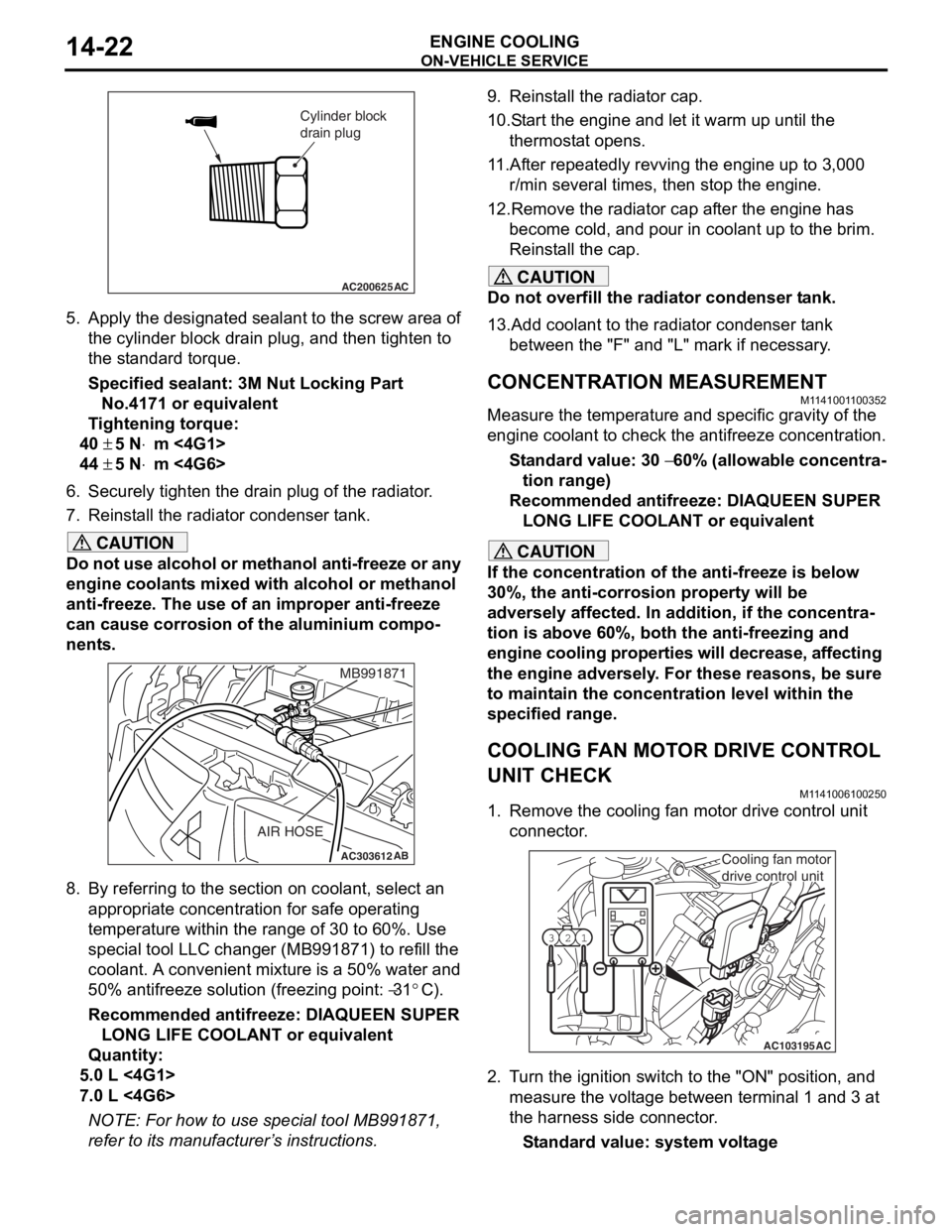
5.App l y the designa ted sealant to t he scre w area of
th e cylin der block drain plu g , and then tighten to
th e st and ard torq ue.
Sp e c ified s ealant: 3 M Nut Loc king Part
No. 4171 o r e quivale n t
Ti ghtenin g torque:
40 ± 5 N⋅m <4G1>
44 ± 5 N⋅m <4G6>
6.Securely tighten t he drain plug of t he radiator .
7.Reinst all the ra diato r con denser t ank.
CAUTION
Do not use alcohol or methanol anti-freeze or any
engine coolants mixed with alcohol or methanol
anti-freeze. The use of an improper anti-freeze
can cause corrosion of the aluminium compo
-
nents.
AC303612AB
MB991871
AIR HOSE
8. By referring to the section on coolant, select an
appropriate concentration for safe operating
temperature within the range of 30 to 60%. Use
special tool LLC changer (MB991871) to refill the
coolant. A convenient mixture is a 50% water and
50% antifreeze solution (freezing point:
−31°C).
Recommended antifreeze: DIAQUEEN SUPER LONG LIFE COOLANT or equivalent
Quantity:
5.0 L <4G1>
7.0 L <4G6>
NOTE: For how to use special tool MB991871,
refer to its manufacturer’s instructions.
9. Reinstall the radiator cap.
10.Start the engine and let it warm up until the thermostat opens.
11.After repeatedly revving the engine up to 3,000 r/min several times, then stop the engine.
12.Remove the radiator cap after the engine has become cold, and pour in coolant up to the brim.
Reinstall the cap.
CAUTION
Do not overfill the radiator condenser tank.
13.Add coolant to the radiator condenser tank between the "F" and "L" mark if necessary.
CONCENTRATION MEASUREMENT
M1141001100352
Measure the temperature and specific gravity of the
engine coolant to check the antifreeze concentration.
Standard value: 30 − 60% (allowable concentra-
tion range)
Recommended antifreeze: DIAQUEEN SUPER
LONG LIFE COOLANT or equivalent
CAUTION
If the concentration of the anti-freeze is below
30%, the anti-corrosion property will be
adversely affected. In addition, if the concentra
-
tion is above 60%, both the anti-freezing and
engine cooling properties will decrease, affecting
the engine adversely. For these reasons, be sure
to maintain the concentration level within the
specified range.
COOLING FAN MOTOR DRIVE CONTROL
UNIT CHECK
M1141006100250
1. Remove the cooling fan motor drive control unit connector.
AC103195
Y1716AU
1
23
AC
Cooling fan motor
drive control unit
2. Turn the ignition switch to the "ON" position, and
measure the voltage between terminal 1 and 3 at
the harness side connector.
Standard value: system voltage
Page 48 of 800

AC303473
18
17 15
20
12
9
13
5
2
9
3
4
1
10
6
10
12 ± 2 N·m
AC
12 ± 2 N·m
16
19
8
11
7
Radiator removal steps
1.Drain plug
2.Radiator cap
3.Radiator condenser tank hose
4.Radiator condenser tank assembly
<>>>A<<5.Radiator upper hose
<>>>A<<6.Radiator lower hose
7.Cooling fan motor drive control unit
connector
8.T/M oil cooler line hose connection
9.Radiator support upper insulator
•Radiator and cooling fan motor &
shroud assembly
10.Radiator support lower insulator
11 .T/M oil cooler line hose
12.Cooling fan motor & shroud
assembly
13.Radiator assembly
Cooling fan motor removal
steps
3.Radiator condenser tank hose
<>>>A<<5.Radiator upper hose
7.Cooling fan motor drive control unit
connector
12.Cooling fan motor & shroud
assembly
15.Cooling fan (L.H.)
16.Cooling fan (R.H.)
17.Cooling fan motor drive control unit
18.Cooling fan motor (L.H.)
19.Cooling fan motor (R.H.)
20.Cooling fan shroud
RADIA T OR
ENGINE COOLING14-34
REMOV A L SER VICE POINT
<> RADIAT OR UPPER HOSE/RADIA-
TO R LOW E R HOSE DISCONNECTION
AC200641AC
Mating marks
Make mating marks on the rad i ator hose and th e
hose
cla m p. Disconnect the ra diat or hoses.
Cooling fan motor removal steps
(Continued)
Page 49 of 800

RADIATOR
ENGINE COOLING14-35
INSTALLATION SERVICE POINT
>>A<< RADIATOR LOWER HOSE/RADIA-
TOR UPPER HOSE CONNECTION
AC200642
Mating marks
Projection
Cooling water hose fitting
or thermostat case assembly
AK
Radiator hose
1.In sert ra diato r lower h o se as fa r as th e projection
o f the cooling wate r inlet hose fit t ing.
2.In sert radia t or up per h o se as far a s t he pro j ection
o f the th ermost at ca se asse mbly .
3.Align th e ma ting marks on the rad i ator hose and
h o se clamp, an d then conn ect the radiator h o se.
REMOVA L AND INST ALLA TION <4G6>
M11 4100 1501 17 1
Pre-removal and Post-installation Operation
•Engine Coolant Draining and Supplying (Refer to
P.14-21).
•Air Cleaner Assembly Removal and Installation (Refer to
GROUP 15
P.15-3).
AC504783
1
12 ± 2 N·m
10
2
3
4
5
6
7
8
9
9
10
11 13
15
18
16
17
12
AB
5.4 ± 0.4 N·m
Radiator removal steps
1.Drain plug
2.Radiator cap
3.Radiator condenser tank hose
4.Radiator condenser tank assembly
<>>>A<<5.Radiator upper hose
<>>>A<<6.Radiator lower hose
7.Cooling fan motor drive control unit
connector
8.T/M oil cooler line hose connection
9.Radiator support upper insulator
•Radiator and cooling fan motor &
shroud assembly
10.Radiator support lower insulator
11 .T/M oil cooler line hose
Radiator removal steps
Page 94 of 800
IGNITION SYSTEM
ENGINE ELECTRICAL16-32
ON-VEHICLE SERVICE
IGNITION COIL (WITH BUILT-IN POWER
TRANSISTOR) CHECK
M1163001200324
Check by the following procedure, and replace if
there is a malfunction.
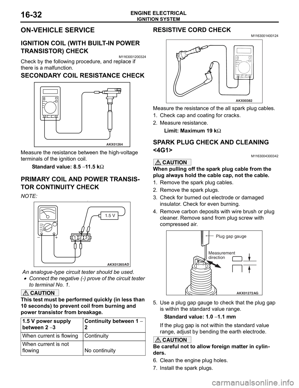
SECONDARY COIL RESISTANCE CHECK
AKX01264
Measure the resist ance bet we en the high- volt ag e
terminals of th
e ign i tio n coil.
St andard va lue: 8.5 − 11 .5 kΩ
PRIM AR Y COIL AND POWER TRANSIS-
TO R CONTINUITY CHECK
NO TE: .•
AKX01265 AD
1.5 V
1 23
+
–
An analogue-t y pe circuit t e ster shou ld be use d .
•Connect the n egative (-) pro v e of the circuit t e ster
to t
e rminal No. 1.
CAUTION
This test must be performed quickly (in less than
10 seconds) to prevent coil from burning and
power transistor from breakage.
1.5 V power supply
between 2
− 3
Continuity between 1 −
2
When current is flowingContinuity
When current is not
flowing
No continuity
RESISTIVE CORD CHECK
M1163001400124
AKX00382
Measure the resistance of the all spark plug cables.
1. Check cap and coating for cracks.
2. Measure resistance.
Limit: Maximum 19 kΩ
SPARK PLUG CHECK AND CLEANING
<4G1>
M1163004300342
CAUTION
When pulling off the spark plug cable from the
plug always hold the cable cap, not the cable.
1. Remove the spark plug cables.
2. Remove the spark plugs.
3. Check for burned out electrode or damaged insulator. Check for even burning.
4. Remove carbon deposits with wire brush or plug cleaner. Remove sand from plug screw with
compressed air.
AKX01272 AG
Plug gap gauge
Measurement
direction
5. Use a plug gap gauge to check that the plug gap is within the standard value range.
Standard value: 1.0 − 1.1 mm
If the plug gap is not within the standard value
range, adjust by bending the earth electrode.
CAUTION
Be careful not to allow foreign matter in cylin-
ders.
6. Clean the engine plug holes.
7. Install the spark plugs.