2006 MERCEDES-BENZ SPRINTER brake light
[x] Cancel search: brake lightPage 956 of 2305
INSTALLATION
WARNING: To avoid personal injury or death, on
vehicles equipped with airbags, disable the supple-
mental restraint system before attempting any
steering wheel, steering column, airbag, seat belt
tensioner, or instrument panel component diagno-
sis or service. Disconnect and isolate the battery
negative (ground) cable, then wait two minutes for
the system capacitor to discharge before perform-
ing further diagnosis or service. This is the only
sure way to disable the supplemental restraint sys-
tem. Failure to take the proper precautions could
result in accidental airbag deployment.
(1) Pull the plunger of the brake lamp switch out-
ward from the switch body to its travel limit (Fig. 5).
(2) Reconnect the vehicle wire harness to the
brake lamp switch connector receptacle.
(3) Depress and hold the brake pedal in the
depressed position until the brake lamp switch
installation is completed (Fig. 4).
(4) Insert the brake lamp switch plunger through
the mounting hole from behind until the switch lock-
ing collar is fully seated against the pedal bracket.
(5) Rotate the brake lamp switch clockwise until
the locking tab on the switch body fully engages the
pedal bracket. Full locking tab engagement will be
accompanied by an audible click.
NOTE: Do not pull the brake pedal upwards as this
will adjust the switch plunger to an incorrect posi-
tion. The switch is properly adjusted when the
switch plunger is just contacting (no gap) the brake
pedal arm with the pedal in the relaxed (released)
position.
(6) Release the brake pedal from its depressed
position to automatically adjust the brake lamp
switch plunger.
(7) Reconnect the battery negative cable.
ADJUSTMENTS
ADJUSTMENT
WARNING: To avoid personal injury or death, on
vehicles equipped with airbags, disable the supple-
mental restraint system before attempting any
steering wheel, steering column, airbag, seat belt
tensioner, or instrument panel component diagno-
sis or service. Disconnect and isolate the battery
negative (ground) cable, then wait two minutes for
the system capacitor to discharge before perform-
ing further diagnosis or service. This is the only
sure way to disable the supplemental restraint sys-tem. Failure to take the proper precautions could
result in accidental airbag deployment.
(1) Disconnect and isolate the battery negative
cable.
(2) Depress and hold the brake pedal in the
depressed position until the brake lamp switch
adjustment is completed.
(3) Pull the plunger of the brake lamp switch out-
ward from the switch body to its travel limit.
NOTE: Do not pull the brake pedal upwards as this
will adjust the switch plunger to an incorrect posi-
tion. The switch is properly adjusted when the
switch plunger is just contacting (no gap) the brake
pedal arm with the pedal in the relaxed (released)
position.
(4) Release the brake pedal from its depressed
position to automatically adjust the brake lamp
switch plunger.
BRAKE / PARK LAMP BULB
REMOVAL
(1) Disconnect and isolate the battery negative
cable.
(2) If the vehicle is so equipped, remove the trim
from the inside of the right or left rear corner pillar.
(3) From inside the vehicle, use hand pressure to
push the two latch tabs toward the center of the tail
lamp unit socket plate and pull the socket plate
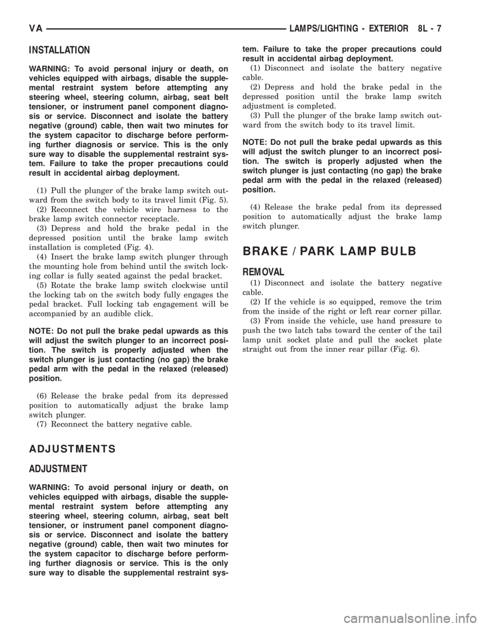
straight out from the inner rear pillar (Fig. 6).
VALAMPS/LIGHTING - EXTERIOR 8L - 7
Page 957 of 2305
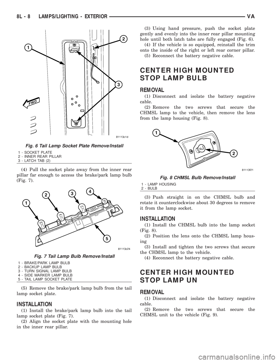
(4) Pull the socket plate away from the inner rear
pillar far enough to access the brake/park lamp bulb
(Fig. 7).
(5) Remove the brake/park lamp bulb from the tail
lamp socket plate.
INSTALLATION
(1) Install the brake/park lamp bulb into the tail
lamp socket plate (Fig. 7).
(2) Align the socket plate with the mounting hole
in the inner rear pillar.(3) Using hand pressure, push the socket plate
gently and evenly into the inner rear pillar mounting
hole until both latch tabs are fully engaged (Fig. 6).
(4) If the vehicle is so equipped, reinstall the trim
onto the inside of the right or left rear corner pillar.
(5) Reconnect the battery negative cable.
CENTER HIGH MOUNTED
STOP LAMP BULB
REMOVAL
(1) Disconnect and isolate the battery negative
cable.
(2) Remove the two screws that secure the
CHMSL lamp to the vehicle, then remove the lens
from the lamp housing (Fig. 8).
(3) Push straight in on the CHMSL bulb and
rotate it counterclockwise about 30 degrees to remove
it from the lamp socket.
INSTALLATION
(1) Install the CHMSL bulb into the lamp socket
(Fig. 8).
(2) Position the lens onto the CHMSL lamp hous-
ing
(3) Install and tighten the two screws that secure
the CHMSL lamp to the vehicle.
(4) Reconnect the battery negative cable.
CENTER HIGH MOUNTED
STOP LAMP UN
REMOVAL
(1) Disconnect and isolate the battery negative
cable.
(2) Remove the two screws that secure the
CHMSL unit to the vehicle (Fig. 9).
Fig. 6 Tail Lamp Socket Plate Remove/Install
1 - SOCKET PLATE
2 - INNER REAR PILLAR
3 - LATCH TAB (2)
Fig. 7 Tail Lamp Bulb Remove/Install
1 - BRAKE/PARK LAMP BULB
2 - BACKUP LAMP BULB
3 - TURN SIGNAL LAMP BULB
4 - SIDE MARKER LAMP BULB
5 - TAIL LAMP SOCKET PLATE
Fig. 8 CHMSL Bulb Remove/Install
1 - LAMP HOUSING
2 - BULB
8L - 8 LAMPS/LIGHTING - EXTERIORVA
Page 970 of 2305

MULTI - FUNCTION SWITCH
REMOVAL
WARNING: To avoid personal injury or death, on
vehicles equipped with airbags, disable the supple-
mental restraint system before attempting any
steering wheel, steering column, airbag, seat belt
tensioner, or instrument panel component diagno-
sis or service. Disconnect and isolate the battery
negative (ground) cable, then wait two minutes for
the system capacitor to discharge before perform-
ing further diagnosis or service. This is the only
sure way to disable the supplemental restraint sys-
tem. Failure to take the proper precautions could
result in accidental airbag deployment.
(1) Disconnect and isolate the battery negative
cable.
(2) Remove the fuse block from the underside of
the steering column. (Refer to 8 - ELECTRICAL/
POWER DISTRIBUTION/FUSE BLOCK -
REMOVAL).
(3) Remove the clockspring from the steering col-
umn. (Refer to 8 - ELECTRICAL/RESTRAINTS/
CLOCKSPRING - REMOVAL).
(4) If the vehicle is so equipped, remove the steer-
ing angle sensor from the steering column. (Refer to
5 - BRAKES/ELECTRICAL/STEERING ANGLE
SENSOR - REMOVAL).
(5) Remove the two screws that secure the upper
shroud to the top of the multi-function switch (Fig.
37).
(6) Remove the upper shroud from the top of the
multi-function switch.
(7) Remove the two screws that secure the multi-
function switch to the steering column.(8) Remove the multi-function switch from the
steering column.
(9) Remove the speed control switch from the back
of the multi-function switch. (Refer to 8 - ELECTRI-
CAL/SPEED CONTROL/SWITCH - REMOVAL).
INSTALLATION
WARNING: To avoid personal injury or death, on
vehicles equipped with airbags, disable the supple-
mental restraint system before attempting any
steering wheel, steering column, airbag, seat belt
tensioner, or instrument panel component diagno-
sis or service. Disconnect and isolate the battery
negative (ground) cable, then wait two minutes for
the system capacitor to discharge before perform-
ing further diagnosis or service. This is the only
sure way to disable the supplemental restraint sys-
tem. Failure to take the proper precautions could
result in accidental airbag deployment.
(1) Reinstall the speed control switch onto the
back of the multi-function switch. (Refer to 8 - ELEC-
TRICAL/SPEED CONTROL/SWITCH - INSTALLA-
TION).
(2) Position the multi-function switch onto the
steering column (Fig. 37).
(3) Install and tighten the two screws that secure
the multi-function switch to the steering column.
(4) Position the upper shroud onto the top of the
multi-function switch.
(5) Install and tighten the two screws that secure
the upper shroud to the top of the multi-function
switch.
(6) If the vehicle is so equipped, reinstall the steer-
ing angle sensor onto the steering column. (Refer to 5
- BRAKES/ELECTRICAL/STEERING ANGLE SEN-
SOR - INSTALLATION).
(7) Reinstall the clockspring onto the steering col-
umn. (Refer to 8 - ELECTRICAL/RESTRAINTS/
CLOCKSPRING - INSTALLATION).
(8) Reinstall the fuse block onto the underside of
the steering column. (Refer to 8 - ELECTRICAL/
POWER DISTRIBUTION/FUSE BLOCK - INSTAL-
LATION).
(9) Reconnect the battery negative cable.
PARK BRAKE SWITCH
REMOVAL
(1) Remove the trim cover from the park brake
lever (Fig. 38). (Refer to 5 - BRAKES/PARKING
BRAKE/LEVER - REMOVAL).
Fig. 37 Multi-Function Switch Remove/Install
1 - SCREW (2)
2 - UPPER SHROUD
3 - SWITCH
4 - SCREW (2)
VALAMPS/LIGHTING - EXTERIOR 8L - 21
Page 971 of 2305
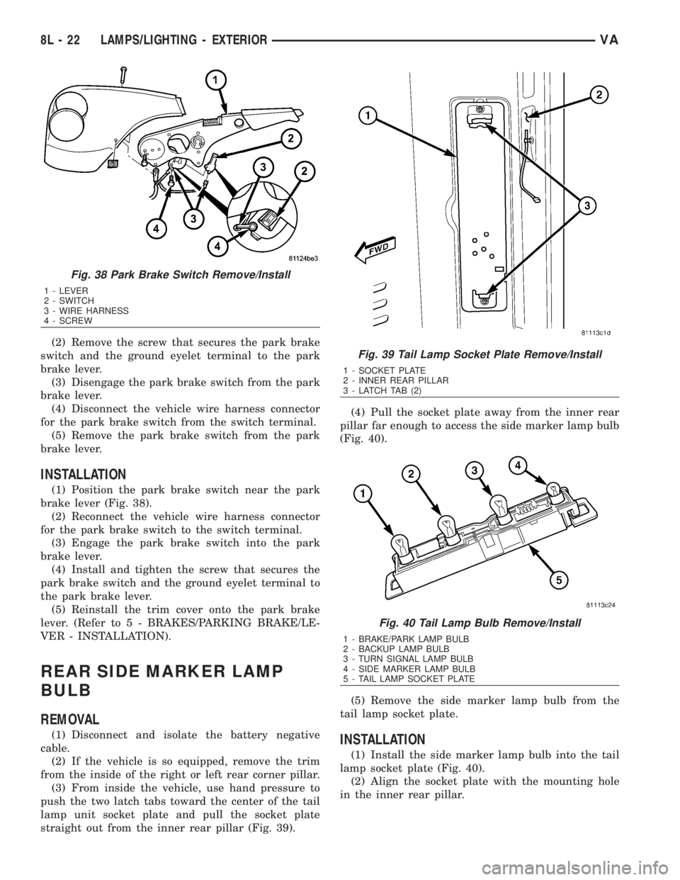
(2) Remove the screw that secures the park brake
switch and the ground eyelet terminal to the park
brake lever.
(3) Disengage the park brake switch from the park
brake lever.
(4) Disconnect the vehicle wire harness connector
for the park brake switch from the switch terminal.
(5) Remove the park brake switch from the park
brake lever.
INSTALLATION
(1) Position the park brake switch near the park
brake lever (Fig. 38).
(2) Reconnect the vehicle wire harness connector
for the park brake switch to the switch terminal.
(3) Engage the park brake switch into the park
brake lever.
(4) Install and tighten the screw that secures the
park brake switch and the ground eyelet terminal to
the park brake lever.
(5) Reinstall the trim cover onto the park brake
lever. (Refer to 5 - BRAKES/PARKING BRAKE/LE-
VER - INSTALLATION).
REAR SIDE MARKER LAMP
BULB
REMOVAL
(1) Disconnect and isolate the battery negative
cable.
(2) If the vehicle is so equipped, remove the trim
from the inside of the right or left rear corner pillar.
(3) From inside the vehicle, use hand pressure to
push the two latch tabs toward the center of the tail
lamp unit socket plate and pull the socket plate
straight out from the inner rear pillar (Fig. 39).(4) Pull the socket plate away from the inner rear
pillar far enough to access the side marker lamp bulb
(Fig. 40).
(5) Remove the side marker lamp bulb from the
tail lamp socket plate.INSTALLATION
(1) Install the side marker lamp bulb into the tail
lamp socket plate (Fig. 40).
(2) Align the socket plate with the mounting hole
in the inner rear pillar.
Fig. 38 Park Brake Switch Remove/Install
1 - LEVER
2 - SWITCH
3 - WIRE HARNESS
4 - SCREW
Fig. 39 Tail Lamp Socket Plate Remove/Install
1 - SOCKET PLATE
2 - INNER REAR PILLAR
3 - LATCH TAB (2)
Fig. 40 Tail Lamp Bulb Remove/Install
1 - BRAKE/PARK LAMP BULB
2 - BACKUP LAMP BULB
3 - TURN SIGNAL LAMP BULB
4 - SIDE MARKER LAMP BULB
5 - TAIL LAMP SOCKET PLATE
8L - 22 LAMPS/LIGHTING - EXTERIORVA
Page 972 of 2305
(3) Using hand pressure, push the socket plate
gently and evenly into the inner rear pillar mounting
hole until both latch tabs are fully engaged (Fig. 39).
(4) If the vehicle is so equipped, reinstall the trim
onto the inside of the right or left rear corner pillar.
(5) Reconnect the battery negative cable.
REAR TURN LAMP BULB
REMOVAL
(1) Disconnect and isolate the battery negative
cable.
(2) If the vehicle is so equipped, remove the trim
from the inside of the right or left rear corner pillar.
(3) From inside the vehicle, use hand pressure to
push the two latch tabs toward the center of the tail
lamp unit socket plate and pull the socket plate
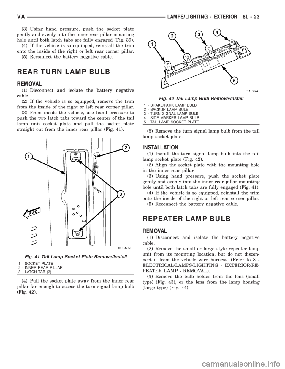
straight out from the inner rear pillar (Fig. 41).
(4) Pull the socket plate away from the inner rear
pillar far enough to access the turn signal lamp bulb
(Fig. 42).(5) Remove the turn signal lamp bulb from the tail
lamp socket plate.
INSTALLATION
(1) Install the turn signal lamp bulb into the tail
lamp socket plate (Fig. 42).
(2) Align the socket plate with the mounting hole
in the inner rear pillar.
(3) Using hand pressure, push the socket plate
gently and evenly into the inner rear pillar mounting
hole until both latch tabs are fully engaged (Fig. 41).
(4) If the vehicle is so equipped, reinstall the trim
onto the inside of the right or left rear corner pillar.
(5) Reconnect the battery negative cable.
REPEATER LAMP BULB
REMOVAL
(1) Disconnect and isolate the battery negative
cable.
(2) Remove the small or large style repeater lamp
unit from its mounting location, but do not discon-
nect it from the vehicle wire harness. (Refer to 8 -
ELECTRICAL/LAMPS/LIGHTING - EXTERIOR/RE-
PEATER LAMP - REMOVAL).
(3) Remove the bulb holder from the lens (small
type) (Fig. 43), or the lens from the lamp housing
(large type) (Fig. 44).
Fig. 41 Tail Lamp Socket Plate Remove/Install
1 - SOCKET PLATE
2 - INNER REAR PILLAR
3 - LATCH TAB (2)
Fig. 42 Tail Lamp Bulb Remove/Install
1 - BRAKE/PARK LAMP BULB
2 - BACKUP LAMP BULB
3 - TURN SIGNAL LAMP BULB
4 - SIDE MARKER LAMP BULB
5 - TAIL LAMP SOCKET PLATE
VALAMPS/LIGHTING - EXTERIOR 8L - 23
Page 1080 of 2305
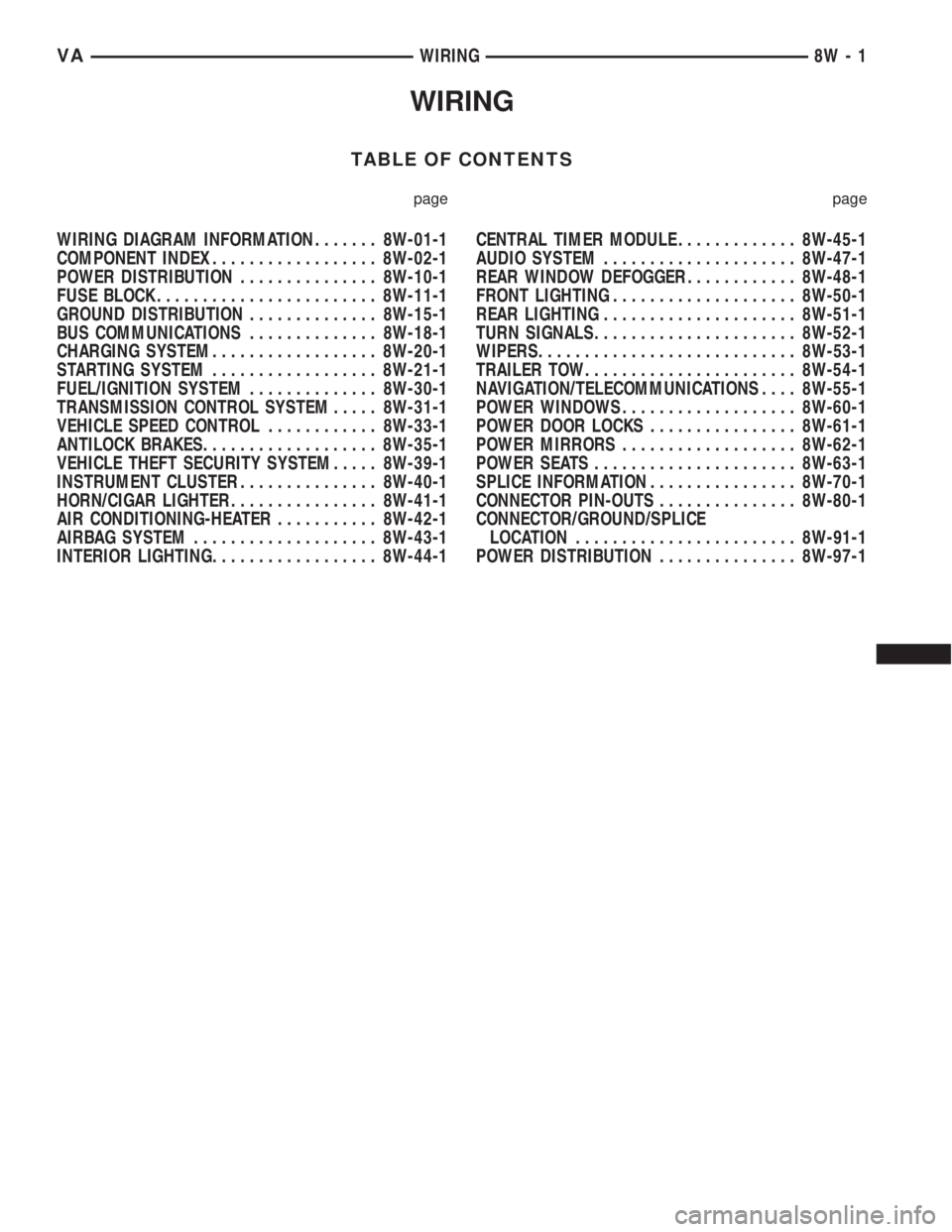
WIRING
TABLE OF CONTENTS
page page
WIRING DIAGRAM INFORMATION....... 8W-01-1
COMPONENT INDEX.................. 8W-02-1
POWER DISTRIBUTION............... 8W-10-1
FUSE BLOCK........................ 8W-11-1
GROUND DISTRIBUTION.............. 8W-15-1
BUS COMMUNICATIONS.............. 8W-18-1
CHARGING SYSTEM.................. 8W-20-1
STARTING SYSTEM.................. 8W-21-1
FUEL/IGNITION SYSTEM.............. 8W-30-1
TRANSMISSION CONTROL SYSTEM..... 8W-31-1
VEHICLE SPEED CONTROL............ 8W-33-1
ANTILOCK BRAKES................... 8W-35-1
VEHICLE THEFT SECURITY SYSTEM..... 8W-39-1
INSTRUMENT CLUSTER............... 8W-40-1
HORN/CIGAR LIGHTER................ 8W-41-1
AIR CONDITIONING-HEATER........... 8W-42-1
AIRBAG SYSTEM.................... 8W-43-1
INTERIOR LIGHTING.................. 8W-44-1CENTRAL TIMER MODULE............. 8W-45-1
AUDIO SYSTEM..................... 8W-47-1
REAR WINDOW DEFOGGER............ 8W-48-1
FRONT LIGHTING.................... 8W-50-1
REAR LIGHTING..................... 8W-51-1
TURN SIGNALS...................... 8W-52-1
WIPERS............................ 8W-53-1
TRAILER TOW....................... 8W-54-1
NAVIGATION/TELECOMMUNICATIONS.... 8W-55-1
POWER WINDOWS................... 8W-60-1
POWER DOOR LOCKS................ 8W-61-1
POWER MIRRORS................... 8W-62-1
POWER SEATS...................... 8W-63-1
SPLICE INFORMATION................ 8W-70-1
CONNECTOR PIN-OUTS............... 8W-80-1
CONNECTOR/GROUND/SPLICE
LOCATION........................ 8W-91-1
POWER DISTRIBUTION............... 8W-97-1 VAWIRING 8W - 1
Page 1092 of 2305
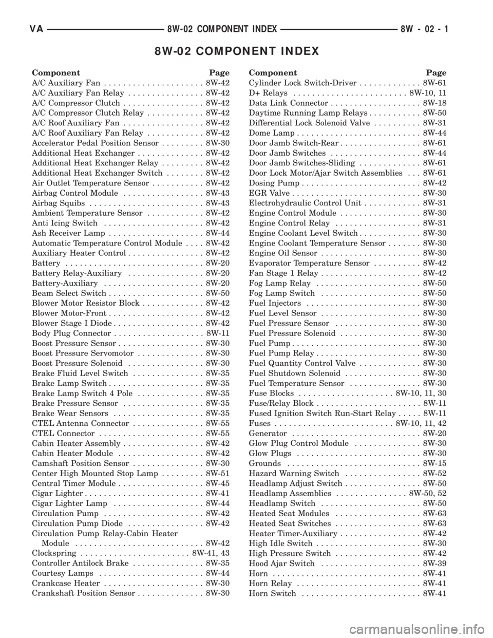
8W-02 COMPONENT INDEX
Component Page
A/C Auxiliary Fan..................... 8W-42
A/C Auxiliary Fan Relay................ 8W-42
A/C Compressor Clutch................. 8W-42
A/C Compressor Clutch Relay............ 8W-42
A/C Roof Auxiliary Fan................. 8W-42
A/C Roof Auxiliary Fan Relay............ 8W-42
Accelerator Pedal Position Sensor......... 8W-30
Additional Heat Exchanger.............. 8W-42
Additional Heat Exchanger Relay......... 8W-42
Additional Heat Exchanger Switch........ 8W-42
Air Outlet Temperature Sensor........... 8W-42
Airbag Control Module................. 8W-43
Airbag Squibs........................ 8W-43
Ambient Temperature Sensor............ 8W-42
Anti Icing Switch..................... 8W-42
Ash Receiver Lamp.................... 8W-44
Automatic Temperature Control Module.... 8W-42
Auxiliary Heater Control................ 8W-42
Battery............................. 8W-20
Battery Relay-Auxiliary................ 8W-20
Battery-Auxiliary..................... 8W-20
Beam Select Switch.................... 8W-50
Blower Motor Resistor Block............. 8W-42
Blower Motor-Front.................... 8W-42
Blower Stage I Diode................... 8W-42
Body Plug Connector................... 8W-11
Boost Pressure Sensor.................. 8W-30
Boost Pressure Servomotor.............. 8W-30
Boost Pressure Solenoid................ 8W-30
Brake Fluid Level Switch............... 8W-35
Brake Lamp Switch.................... 8W-35
Brake Lamp Switch 4 Pole.............. 8W-35
Brake Pressure Sensor................. 8W-35
Brake Wear Sensors................... 8W-35
CTEL Antenna Connector............... 8W-55
CTEL Connector...................... 8W-55
Cabin Heater Assembly................. 8W-42
Cabin Heater Module.................. 8W-42
Camshaft Position Sensor............... 8W-30
Center High Mounted Stop Lamp......... 8W-51
Central Timer Module.................. 8W-45
Cigar Lighter......................... 8W-41
Cigar Lighter Lamp................... 8W-44
Circulation Pump..................... 8W-42
Circulation Pump Diode................ 8W-42
Circulation Pump Relay-Cabin Heater
Module........................... 8W-42
Clockspring....................... 8W-41, 43
Controller Antilock Brake............... 8W-35
Courtesy Lamps...................... 8W-44
Crankcase Heater..................... 8W-30
Crankshaft Position Sensor.............. 8W-30Component Page
Cylinder Lock Switch-Driver............. 8W-61
D+ Relays........................ 8W-10, 11
Data Link Connector................... 8W-18
Daytime Running Lamp Relays........... 8W-50
Differential Lock Solenoid Valve.......... 8W-31
Dome Lamp.......................... 8W-44
Door Jamb Switch-Rear................. 8W-61
Door Jamb Switches................... 8W-44
Door Jamb Switches-Sliding............. 8W-61
Door Lock Motor/Ajar Switch Assemblies . . . 8W-61
Dosing Pump......................... 8W-42
EGR Valve........................... 8W-30
Electrohydraulic Control Unit............ 8W-31
Engine Control Module................. 8W-30
Engine Control Relay.................. 8W-31
Engine Coolant Level Switch............. 8W-30
Engine Coolant Temperature Sensor....... 8W-30
Engine Oil Sensor..................... 8W-30
Evaporator Temperature Sensor.......... 8W-42
Fan Stage 1 Relay..................... 8W-42
Fog Lamp Relay...................... 8W-50
Fog Lamp Switch..................... 8W-50
Fuel Injectors........................ 8W-30
Fuel Level Sensor..................... 8W-30
Fuel Pressure Sensor.................. 8W-30
Fuel Pressure Solenoid................. 8W-30
Fuel Pump........................... 8W-30
Fuel Pump Relay...................... 8W-30
Fuel Quantity Control Valve............. 8W-30
Fuel Shutdown Solenoid................ 8W-30
Fuel Temperature Sensor............... 8W-30
Fuse Blocks.................... 8W-10, 11, 30
Fuse/Relay Block...................... 8W-11
Fused Ignition Switch Run-Start Relay..... 8W-11
Fuses......................... 8W-10, 11, 42
Generator........................... 8W-20
Glow Plug Control Module.............. 8W-30
Glow Plugs.......................... 8W-30
Grounds............................ 8W-15
Hazard Warning Switch................ 8W-52
Headlamp Adjust Switch................ 8W-50
Headlamp Assemblies............... 8W-50, 52
Headlamp Switch..................... 8W-50
Heated Seat Modules.................. 8W-63
Heated Seat Switches.................. 8W-63
Heater Timer-Auxiliary................. 8W-42
High Idle Switch...................... 8W-30
High Pressure Switch.................. 8W-42
Hood Ajar Switch..................... 8W-39
Horn............................... 8W-41
Horn Relay.......................... 8W-41
Horn Switch......................... 8W-41
VA8W-02 COMPONENT INDEX 8W - 02 - 1
Page 1093 of 2305
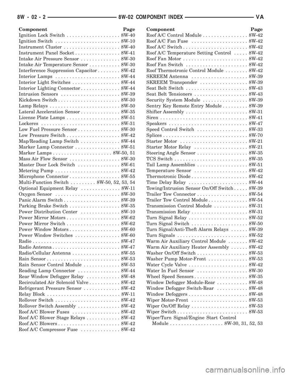
Component Page
Ignition Lock Switch................... 8W-40
Ignition Switch....................... 8W-10
Instrument Cluster.................... 8W-40
Instrument Panel Socket................ 8W-41
Intake Air Pressure Sensor.............. 8W-30
Intake Air Temperature Sensor........... 8W-30
Interference Suppression Capacitor........ 8W-42
Interior Lamps....................... 8W-44
Interior Light Switches................. 8W-44
Interior Lighting Connector.............. 8W-44
Intrusion Sensors..................... 8W-39
Kickdown Switch...................... 8W-30
Lamp Relays......................... 8W-50
Lateral Acceleration Sensor.............. 8W-35
License Plate Lamps................... 8W-51
Lockeres............................ 8W-31
Low Fuel Pressure Sensor............... 8W-30
Low Pressure Switch................... 8W-42
Map/Reading Lamp Switch.............. 8W-44
Marker Lamp Connector................ 8W-51
Marker Lamps..................... 8W-50, 51
Mass Air Flow Sensor.................. 8W-30
Master Door Lock Switch............... 8W-61
Metering Pump....................... 8W-42
Microphone Connector.................. 8W-55
Multi-Function Switch......... 8W-50, 52, 53, 54
Optional Equipment Relay.............. 8W-11
Oxygen Sensor....................... 8W-30
Panic Alarm Switch.................... 8W-39
Parking Brake Switch.................. 8W-35
Power Distribution Center.............. 8W-10
Power Mirror Motors................... 8W-62
Power Mirror Switch................... 8W-62
Power Window Motors.................. 8W-60
Power Window Switches................ 8W-60
Radio............................... 8W-47
Radio Antenna........................ 8W-47
Radio/Cellular Antenna................. 8W-55
Rain Sensor.......................... 8W-53
Rain Sensor Control Module............. 8W-53
Reading Lamp Connector............... 8W-44
Rear Window Defogger Relay............ 8W-48
Recirculated Air Solenoid Valve........... 8W-42
Refrigerant Pressure Sensor............. 8W-42
Relay Block.......................... 8W-11
Rollover Switch....................... 8W-42
Rollover Switch Assembly............... 8W-42
Roof A/C Blower Fuses................. 8W-42
Roof A/C Blower Stage Relays............ 8W-42
Roof A/C Blowers...................... 8W-42
Roof A/C Compressor Fuse.............. 8W-42Component Page
Roof A/C Control Module................ 8W-42
Roof A/C Fan Fuse.................... 8W-42
Roof A/C Switch....................... 8W-42
Roof A/C Temperature Setting Control..... 8W-42
Roof Fan Motor....................... 8W-42
Roof Fan Switch...................... 8W-42
Roof Thermotronic Control Module........ 8W-42
SKREEM Antenna.................... 8W-39
SKREEM Transponder................. 8W-39
Seat Belt Switch...................... 8W-43
Seat Belt Tensioners................... 8W-43
Security System Module................ 8W-39
Sentry Key Remote Entry Module......... 8W-39
Shifter Assembly...................... 8W-31
Siren............................... 8W-41
Speakers............................ 8W-47
Speed Control Switch.................. 8W-33
Splices.............................. 8W-70
Starter Motor........................ 8W-21
Starter Motor Relay................... 8W-21
Steering Angle Sensor.................. 8W-35
TCS Switch.......................... 8W-35
Tail Lamp Assemblies.................. 8W-51
Temperature Sensor................... 8W-42
Thermotronic Diode.................... 8W-42
Time Delay Relay..................... 8W-44
Towing/Intrusion Sensor On/Off Switch..... 8W-39
Trailer Tow Connector.................. 8W-54
Trailer Tow Control Module.............. 8W-54
Transmission Control Module............ 8W-31
Transmission Relay.................... 8W-31
Turn Signal Relay..................... 8W-52
Turn Signal Switch.................... 8W-50
Turn Signal/Anti-Theft Alarm Relays...... 8W-39
Turn Signals......................... 8W-52
Warm Air Auxiliary Control Module....... 8W-42
Warm Air Auxiliary Heater Assembly...... 8W-42
Washer On/Off Switch.................. 8W-53
Washer Pump Motor-Front.............. 8W-53
Water Cycle Valve..................... 8W-42
Water In Fuel Sensor.................. 8W-30
Wheel Speed Sensors................... 8W-35
Window Defogger Module-Rear........... 8W-48
Window Defogger Switch-Rear........... 8W-48
Window Defoggers..................... 8W-48
Wiper Motor-Front.................... 8W-53
Wiper On/Off Relay.................... 8W-53
Wiper Switch......................... 8W-53
Wiper/Turn Signal/Engine Start Control
Module................... 8W-30, 31, 52, 53
8W - 02 - 2 8W-02 COMPONENT INDEXVA