Page 38 of 481

37 Getting started
Unlocking
For information on starting the engine, see
(�page 50).
iWhen you switch on ignition, the indi-
cator and warning lamps (except high
beam headlamp indicator lamp and
turn signal indicator lamps unless acti-
vated) in the instrument cluster come
on. The indicator and warning lamps
(except high beam headlamp indicator
lamp and turn signal indicator lamps if
activated) will go out when the engine
is running. This indicates that the re-
spective systems are operational.iVehicles with automatic transmission*:
The SmartKey can only be removed
from the starter switch with the gear
selector lever in positionP.
!If the SmartKey cannot be turned in the
starter switch, the vehicle battery may
not be sufficiently charged.�
Check the vehicle battery and
charge it if necessary (
�page 421).
�
Get a jump start (
�page 424).
To prevent accelerated vehicle battery
discharge or a completely discharged
vehicle battery, always remove the
SmartKey from the starter switch when
the engine is not in operation.
Page 56 of 481
55 Getting started
Driving
Switching on headlamps
Low beam headlamps
The exterior lamp switch is located on the
dashboard to the left of the steering wheel.Exterior lamp switch1Off
2Low beam headlamps on�
Turn exterior lamp switch to
positionB.High beam
The combination switch is located on the
left of the steering column.
Combination switch1High beam
2High beam flasher�
Push combination switch in direction of
arrow1.
The high beam headlamp indicator
lampA in the instrument cluster
comes on (
�page 24).
For more information on headlamps, see
“Lighting” (
�page 110).
Turn signals
The combination switch is located on the
left of the steering column.Combination switch1Turn signals, right
2Turn signals, left
Page 57 of 481

56 Getting startedDriving�
Press combination switch in direction
of arrow1 or2.
The corresponding turn signal indicator
lampKorL in the instrument
cluster flashes (
�page 24).
The combination switch resets auto-
matically after major directional chang-
es.
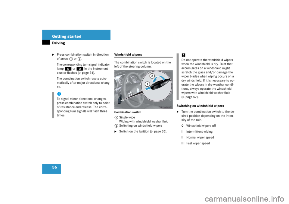
Windshield wipers
The combination switch is located on the
left of the steering column.Combination switch1Single wipe
Wiping with windshield washer fluid
2Switching on windshield wipers�
Switch on the ignition (
�page 36).Switching on windshield wipers
�
Turn the combination switch to the de-
sired position depending on the inten-
sity of the rain.
0Windshield wipers off
IIntermittent wiping
IINormal wiper speed
IIIFast wiper speed
iTo signal minor directional changes,
press combination switch only to point
of resistance and release. The corre-
sponding turn signals will flash three
times.
!Do not operate the windshield wipers
when the windshield is dry. Dust that
accumulates on a windshield might
scratch the glass and/or damage the
wiper blades when wiping occurs on a
dry windshield. If it is necessary to op-
erate the wipers in dry weather condi-
tions, always operate the windshield
wipers with windshield washer fluid
(�page 57).
Page 70 of 481

69 Safety and Security
Occupant safety
When you sell your vehicle, we strongly
urge you to give notice to the subsequent
owner that it is equipped with an SRS by
alerting them to the applicable section in
the Operator’s Manual.
and installation of additional electri-
cal/electronic equipment on or near
SRS components and wiring. Keep area
between air bags and occupants free
from objects (e.g. packages, purses,
umbrellas, etc.).
�
Do not pass belts over sharp edges.
They could tear.
�
Do not make any modification that could
change the effectiveness of the belts.
�
Do not bleach or dye seat belts as this
may severely weaken them. In a crash
they may not be able to provide ade-
quate protection.
�
Never place your feet on the instrument
panel, or on the seat. Always keep both
feet on the floor in front of the seat.
�
Air bag system components will be hot
after an air bag has inflated. Do not
touch.
�
In addition, improper repair work on the
SRS creates a risk of rendering the SRS
inoperative or causing unintended
air bag deployment. Work on the SRS
must therefore only be performed by
qualified technicians. Contact an autho-
rized Mercedes-Benz Center.
�
For your protection and the protection
of others, when scrapping the air bag
unit or emergency tensioning device,
our safety instructions must be fol-
lowed. These instructions are available
from your authorized Mercedes-Benz
Center.
�
Given the considerable deployment
speed and the textile structure of the
air bags, there is the possibility of abra-
sions or other injuries resulting from
air bag deployment.
Warning!
G
Only use seat covers which have been test-
ed and approved by Mercedes-Benz for your
vehicle model. Using other seat covers may
interfere with or prevent the deployment of
the head-thorax airbags. Contact your au-
thorized Mercedes-Benz Center for availabil-
ity.
Page 71 of 481

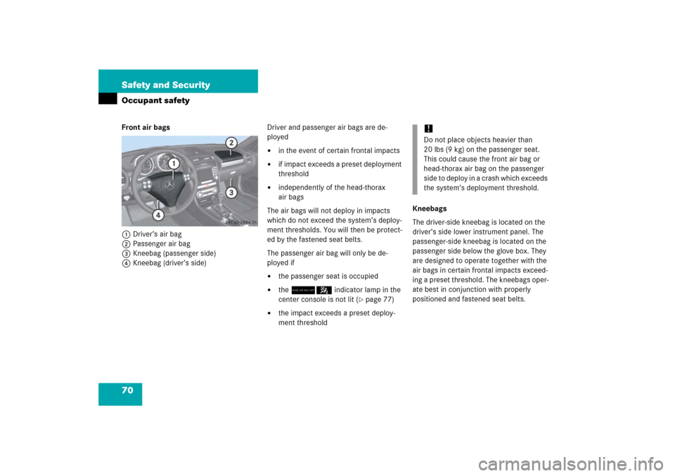
70 Safety and SecurityOccupant safetyFront air bags
1Driver’s air bag
2Passenger air bag
3Kneebag (passenger side)
4Kneebag (driver’s side)Driver and passenger air bags are de-
ployed
�
in the event of certain frontal impacts
�
if impact exceeds a preset deployment
threshold
�
independently of the head-thorax
air bags
The air bags will not deploy in impacts
which do not exceed the system’s deploy-
ment thresholds. You will then be protect-
ed by the fastened seat belts.
The passenger air bag will only be de-
ployed if
�
the passenger seat is occupied
�
the 75indicator lamp in the
center console is not lit (
�page 77)
�
the impact exceeds a preset deploy-
ment thresholdKneebags
The driver-side kneebag is located on the
driver’s side lower instrument panel. The
passenger-side kneebag is located on the
passenger side below the glove box. They
are designed to operate together with the
air bags in certain frontal impacts exceed-
ing a preset threshold. The kneebags oper-
ate best in conjunction with properly
positioned and fastened seat belts.
!Do not place objects heavier than
20 lbs (9 kg) on the passenger seat.
This could cause the front air bag or
head-thorax air bag on the passenger
side to deploy in a crash which exceeds
the system’s deployment threshold.
Page 75 of 481

74 Safety and SecurityOccupant safety
Emergency tensioning device (ETD),
seat belt force limiter
The seat belts are equipped with
emergency tensioning devices (ETDs) and
seat belt force limiters.
The ETD is designed to activate in the fol-
lowing cases:�
in frontal or rear-end impacts exceed-
ing a preset severity level.
�
if the restraint systems are operational
and functioning correctly, see
1indicator lamp (
�page 64).In an impact emergency tensioning
devices remove slack from the belts in
such a way that the seat belts fit more
snugly against the body. Belt force limiters
reduce the force exerted by the seat belts
on occupants during a crash.
�
Belts should not be worn twisted. In a
crash, you wouldn’t have the full width
of the belt to manage impact forces. The
twisted belt against your body could
cause injuries.
�
Pregnant women should also use a
lap-shoulder belt. The lap belt portion
should be positioned as low as possible
on the hips to avoid any possible pres-
sure on the abdomen.
�
Never place your feet on the instrument
panel, dashboard or on the seat. Always
keep both feet on the floor in front of the
seat.
iThe ETDs for the seats will only activate
if the respective seat belt is fastened
(latch plate properly inserted into
buckle).
Warning!
G
An emergency tensioning device (ETD) that
was activated must be replaced.
When scrapping the emergency tensioning
device, our safety instructions must be fol-
lowed. These are available at your autho-
rized Mercedes-Benz Center.
��
Page 92 of 481
91 Controls in detail
Locking and unlocking
Seats
Memory function*
Lighting
Instrument cluster
Control system
Manual transmission
Automatic transmission*
Good visibility
Climate control
Automatic climate control*
Audio system
Power windows
Retractable hardtop
Driving systems
Useful features
Page 111 of 481

110 Controls in detailLightingFor information on how to switch on the
headlamps and use the turn signals, see
“Switching on headlamps” (
�page 55)
and “Turn signals” (
�page 55).
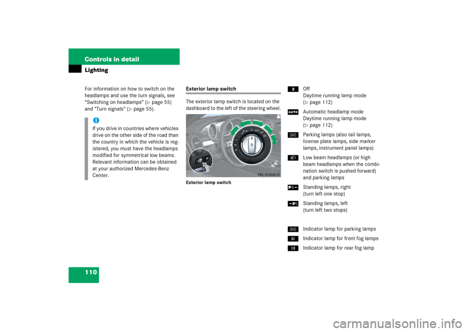
Exterior lamp switch
The exterior lamp switch is located on the
dashboard to the left of the steering wheel.Exterior lamp switch
MOff
Daytime running lamp mode
(
�page 112)
UAutomatic headlamp mode
Daytime running lamp mode
(�page 112)
CParking lamps (also tail lamps,
license plate lamps, side marker
lamps, instrument panel lamps)
BLow beam headlamps (or high
beam headlamps when the combi-
nation switch is pushed forward)
and parking lamps
ˆStanding lamps, right
(turn left one stop)
‚Standing lamps, left
(turn left two stops)
CIndicator lamp for parking lamps
‡Indicator lamp for front fog lamps
†Indicator lamp for rear fog lamp
iIf you drive in countries where vehicles
drive on the other side of the road than
the country in which the vehicle is reg-
istered, you must have the headlamps
modified for symmetrical low beams.
Relevant information can be obtained
at your authorized Mercedes-Benz
Center.