Page 403 of 481

402 Practical hintsReplacing bulbs
Notes on bulb replacement�
Only use 12-volt bulbs of the same type
and with the specified watt rating.
�
Switch lights off before changing a bulb
to prevent short circuits.
�
Always use a clean lint-free cloth when
handling bulbs.
�
Your hands should be dry and free of oil
and grease.
�
If the newly installed bulb does not
come on, visit an authorized
Mercedes-Benz Center.Have the LEDs and bulbs for the following
lamps replaced by an authorized
Mercedes-Benz Center:
�
Additional turn signal lamps in the
exterior rear view mirrors
�
Bi-Xenon* lamps
�
Front fog lamps
�
High mounted brake lamp
�
Brake lamps
�
Front and rear side marker lamps
�
Parking/standing lamps in the tail
lamp assemblies
Warning!
G
Bulbs and bulb sockets can be very hot. Al-
low the lamp to cool down before changing
a bulb.
Keep bulbs out of reach of children.
Halogen lamps contain pressurized gas.
A bulb can explode if you:�
touch or move it when hot
�
drop the bulb
�
scratch the bulb
Wear eye and hand protection.
Because of high voltage in Xenon lamps, it is
dangerous to replace the bulb or repair the
lamp and its components. We recommend
that you have such work done by a qualified
technician.
iHave the headlamp adjustment
checked regularly.
Page 404 of 481
403 Practical hints
Replacing bulbs
Replacing bulbs for front lamps
Before you start to replace a bulb for a
front lamp, do the following first:�
Turn the exterior lamp switch to
positionM (
�page 110).
�
Open the hood (
�page 307).
1Housing cover for low beam (halogen
headlamps only)
Housing cover for Bi-Xenon* head-
lamps. Do not remove.
2Bulb socket for turn signal lamp
3Bulb socket for high beam/high beam
flasher lamp
4Bulb socket for parking and standing
light lamp
5Bulb socket for low beam bulb
(Halogen headlamps only)
Warning!
G
Do not remove the cover1 for the
Bi-Xenon* headlamp. Because of high volt-
age in Bi-Xenon lamps, it is dangerous to re-
place the bulb or repair the lamp and its
components. We recommend that you have
such work done by a qualified technician.
Page 411 of 481

410 Practical hintsFlat tire�
Screw the air pump’s air hose5 onto
flange6 of the TIREFIT container.
�
Stick TIREFIT container1 upside
down into notch3 of the electric air
pump.
7Tire valve
8Electric air pump switch
9Pressure gauge and vent screw
aFiller hose
�
Unscrew the valve cap from tire
valve7.
�
Screw filler hosea onto tire valve7.
�
Close vent screw9 on air hose4.
�
Insert electrical plug4 into the power
outlet in the passenger footwell
(�page 271).
�
Turn the SmartKey in the starter switch
to position1 (
�page 36).
�
Press I on electric air pump switch8.
The electric air pump should now
switch on and inflate the tire.After 5 minutes, the pressure gauge must
display at least 26 psi (1.8 bar). The air
hose can become hot during inflation.
Please exercise appropriate caution.
�
If this tire inflation pressure is not at-
tained, turn off the electric air pump,
detach the filler hose from the tire
valve, and drive vehicle back and forth
very slowly approximately 30 ft (10 m).
This serves to better distribute the
TIREFIT sealant material inside the tire.
�
Unscrew the air pump’s air hose5
from flange6 of the TIREFIT contain-
er.
�
Screw air hose5onto tire valve7.
�
Inflate the tire again.
Warning!
G
Observe safety instructions on air pump la-
bel.
!The cigarette lighter (
�page 270) is
not designed for use with the electric
air pump. Use the power outlet in the
passenger footwell (
�page 271) for
electric air pump operation.
!Do not operate the electric air pump
longer than 6 minutes without interrup-
tion. Otherwise it may overheat.
You may operate the air pump again af-
ter it has cooled off.
��
Page 416 of 481
415 Practical hints
Flat tire
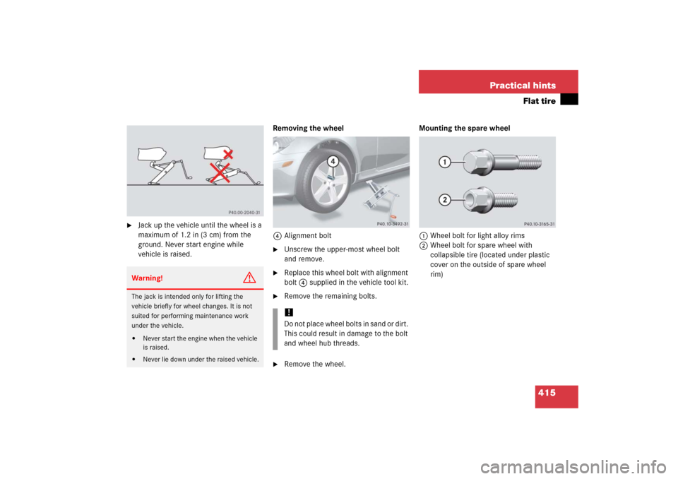
�
Jack up the vehicle until the wheel is a
maximum of 1.2 in (3 cm) from the
ground. Never start engine while
vehicle is raised.Removing the wheel
4Alignment bolt
�
Unscrew the upper-most wheel bolt
and remove.
�
Replace this wheel bolt with alignment
bolt4 supplied in the vehicle tool kit.
�
Remove the remaining bolts.
�
Remove the wheel.Mounting the spare wheel
1Wheel bolt for light alloy rims
2Wheel bolt for spare wheel with
collapsible tire (located under plastic
cover on the outside of spare wheel
rim)
Warning!
G
The jack is intended only for lifting the
vehicle briefly for wheel changes. It is not
suited for performing maintenance work
under the vehicle.�
Never start the engine when the vehicle
is raised.
�
Never lie down under the raised vehicle.
!Do not place wheel bolts in sand or dirt.
This could result in damage to the bolt
and wheel hub threads.
Page 417 of 481
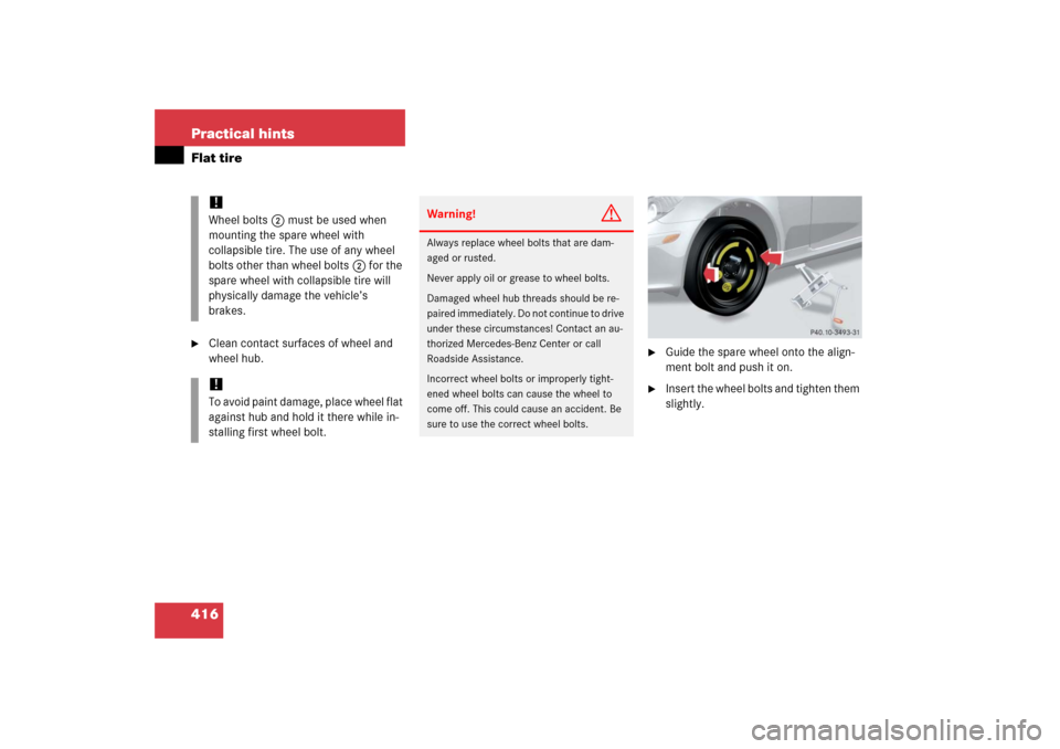
416 Practical hintsFlat tire�
Clean contact surfaces of wheel and
wheel hub.
�
Guide the spare wheel onto the align-
ment bolt and push it on.
�
Insert the wheel bolts and tighten them
slightly.
!Wheel bolts2 must be used when
mounting the spare wheel with
collapsible tire. The use of any wheel
bolts other than wheel bolts2 for the
spare wheel with collapsible tire will
physically damage the vehicle’s
brakes. !To avoid paint damage, place wheel flat
against hub and hold it there while in-
stalling first wheel bolt.
Warning!
G
Always replace wheel bolts that are dam-
aged or rusted.
Never apply oil or grease to wheel bolts.
Damaged wheel hub threads should be re-
paired immediately. Do not continue to drive
under these circumstances! Contact an au-
thorized Mercedes-Benz Center or call
Roadside Assistance.
Incorrect wheel bolts or improperly tight-
ened wheel bolts can cause the wheel to
come off. This could cause an accident. Be
sure to use the correct wheel bolts.
Page 418 of 481
417 Practical hints
Flat tire
�
Unscrew the alignment bolt, install last
wheel bolt and tighten slightly.
�
Inflate the collapsible tire
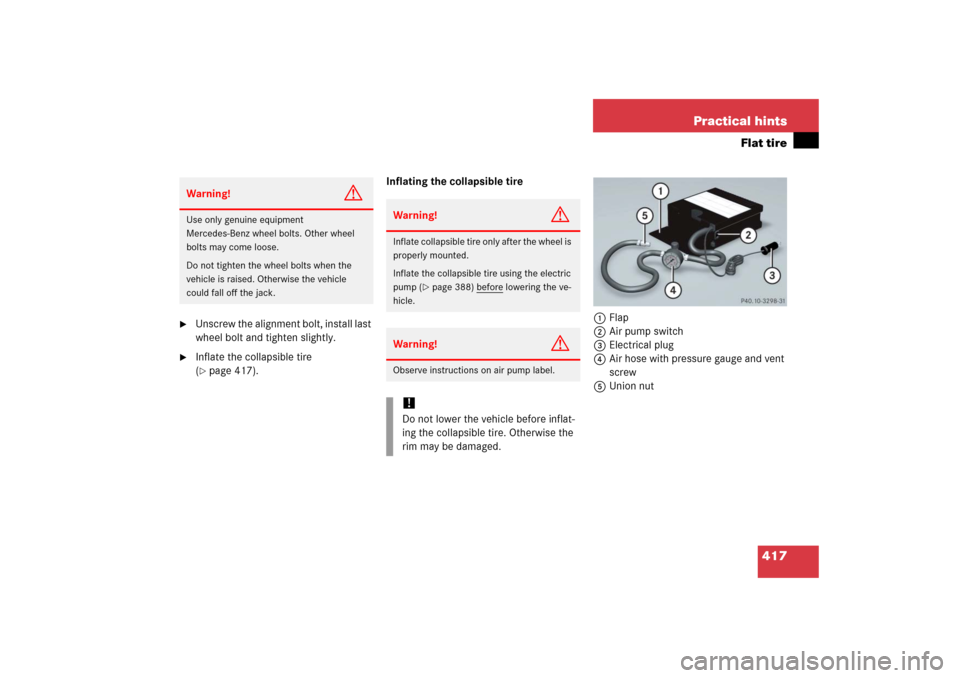
(�page 417).Inflating the collapsible tire
1Flap
2Air pump switch
3Electrical plug
4Air hose with pressure gauge and vent
screw
5Union nut
Warning!
G
Use only genuine equipment
Mercedes-Benz wheel bolts. Other wheel
bolts may come loose.
Do not tighten the wheel bolts when the
vehicle is raised. Otherwise the vehicle
could fall off the jack.
Warning!
G
Inflate collapsible tire only after the wheel is
properly mounted.
Inflate the collapsible tire using the electric
pump (
�page 388) before
lowering the ve-
hicle.
Warning!
G
Observe instructions on air pump label.!Do not lower the vehicle before inflat-
ing the collapsible tire. Otherwise the
rim may be damaged.
Page 419 of 481
.
�
Open flap1 on air pump.
�
Pull out electrical plug3 and air hose
with pressure gauge4.
�
Close vent screw on")
418 Practical hintsFlat tire�
Take the electric air pump out of the
trunk (
�page 388).
�
Open flap1 on air pump.
�
Pull out electrical plug3 and air hose
with pressure gauge4.
�
Close vent screw on air hose4.
�
Remove the valve cap from the tire
valve.
�
Screw air hose4 with union nut5
onto the collapsible tire valve.
�
Make sure electric air pump switch2
is set to0.
�
Insert electrical plug3 into the power
outlet in the passenger footwell
(�page 271).
�
Turn the SmartKey in the starter switch
to position1.
�
PressI on electric air pump switch2.
The electric air pump switches on and
inflates the collapsible tire.
�
Inflate the collapsible tire to approxi-
mately 51 psi (3.5 bar).
This takes about 5 minutes for the col-
lapsible tire. Air hose4 and union
nut5 can become hot during infla-
tion. Exercise proper caution to avoid
burning yourself when using the equip-
ment.
�
Press0 on electric air pump switch2.
�
Turn the SmartKey in the starter switch
to position0.
The electric air pump should now be
switched off.
�
If the tire inflation pressure is above
51 psi (3.5 bar), release excess tire in-
flation pressure using the vent screw
on air hose4.
!The cigarette lighter (
�page 270) is
not designed for use with the electric
air pump. Use the power outlet in the
passenger footwell (
�page 271) for
electric air pump operation.
!Do not operate the electric air pump
longer than 6 minutes without interrup-
tion. Otherwise it may overheat.
You may operate the electric air pump
again after it has cooled off.
Page 426 of 481

425 Practical hints
Jump starting
�
Make sure the two vehicles do not
touch.
�
Turn off all electrical consumers.
�
Apply parking brake.
�
Shift gear selector lever* to positionP
(manual transmission to Neutral).
�
Open the hood (
�page 307).
�
Flip up cover from positive under hood
terminal2 in front of water tray1
(�page 422).1Positive terminal of charged battery
2Positive under hood terminal in front of
water tray
3Negative under hood terminal in front
of water tray
4Negative terminal of charged battery
�
Connect positive terminal1 of the
charged battery with positive under
hood terminal2 in front of the water
tray with one jumper cable. Clamp the
cable to positive terminal1 of the
charged battery first.
�
Start the engine of the vehicle with the
charged battery and run at idle speed.
�
Connect negative terminal4 of the
charged battery with negative under
hood terminal3 in front of the water
tray with the second jumper cable.
Clamp the cable to negative
terminal4 of the charged battery
first.
�
Start the engine of the disabled vehi-
cle.
You can now turn on the electrical con-
sumers. Do not turn on the lights under
any circumstances.
�
Remove the jumper cables first from
negative terminals3 and4 and then
from positive terminals2 and1.
You can now turn on the lights.
�
Have the battery checked at the near-
est authorized Mercedes-Benz Center.
Warning!
G
Keep flames or sparks away from battery.
Do not smoke.
Observe all safety instructions and precau-
tions when handling automotive batteries
(�page 314).
!Never invert the terminal connections.
iVehicles with automatic transmission*:
Do not tow-start vehicle.