Page 375 of 481
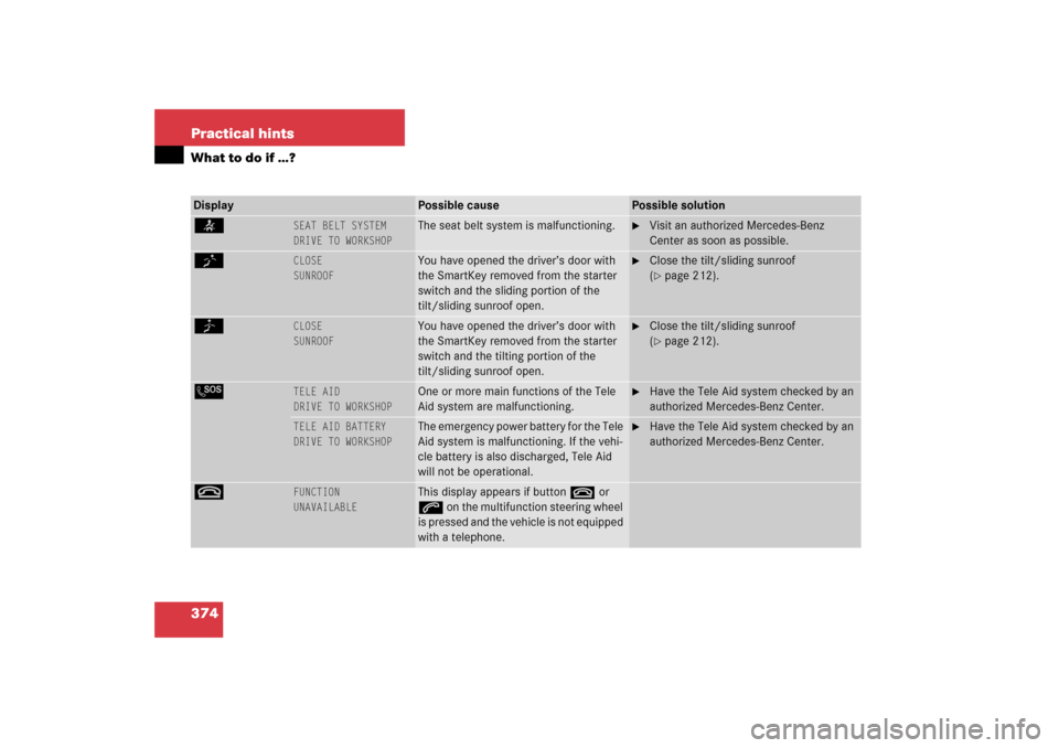
374 Practical hintsWhat to do if …?Display
Possible cause
Possible solution
<
SEAT BELT SYSTEM
DRIVE TO WORKSHOP
The seat belt system is malfunctioning.
�
Visit an authorized Mercedes-Benz
Center as soon as possible.
K
CLOSE
SUNROOF
You have opened the driver’s door with
the SmartKey removed from the starter
switch and the sliding portion of the
tilt/sliding sunroof open.
�
Close the tilt/sliding sunroof
(�page 212).
J
CLOSE
SUNROOF
You have opened the driver’s door with
the SmartKey removed from the starter
switch and the tilting portion of the
tilt/sliding sunroof open.
�
Close the tilt/sliding sunroof
(�page 212).
L
TELE AID
DRIVE TO WORKSHOP
One or more main functions of the Tele
Aid system are malfunctioning.
�
Have the Tele Aid system checked by an
authorized Mercedes-Benz Center.
TELE AID BATTERY
DRIVE TO WORKSHOP
The emergency power battery for the Tele
Aid system is malfunctioning. If the vehi-
cle battery is also discharged, Tele Aid
will not be operational.
�
Have the Tele Aid system checked by an
authorized Mercedes-Benz Center.
t
FUNCTION
UNAVAILABLE
This display appears if button t or
s on the multifunction steering wheel
is pressed and the vehicle is not equipped
with a telephone.
Page 389 of 481
388 Practical hintsUnlocking/locking in an emergencyUnlocking the vehicle
If you are unable to unlock the vehicle with
the SmartKey or KEYLESS-GO*, open the
driver’s door and the trunk using the me-
chanical key. Removing the mechanical key
1Mechanical key locking tab
2Mechanical key
�
Move locking tab1 in the direction of
arrow.
�
Slide mechanical key2 out of the
housing.Unlocking the driver’s door
1Unlocking
�
Insert the mechanical key into the driv-
er’s door lock until it stops.
�
Turn the mechanical key counterclock-
wise to position1.
The driver’s door is unlocked.
iUnlocking the driver’s door and/or the
trunk with the mechanical key will trig-
ger the anti-theft alarm system.
To cancel the alarm, insert the
SmartKey or SmartKey with
KEYLESS-GO* in the starter switch.
Page 390 of 481
389 Practical hints
Unlocking/locking in an emergency
Unlocking the trunk
A minimum height clearance of 6 ft.
(1.85 m) is required to open the trunk lid.
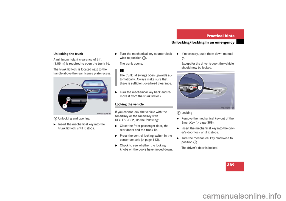
The trunk lid lock is located next to the
handle above the rear license plate recess.
1Unlocking and opening�
Insert the mechanical key into the
trunk lid lock until it stops.
�
Turn the mechanical key counterclock-
wise to position1.
The trunk opens.
�
Turn the mechanical key back and re-
move it from the trunk lid lock.
Locking the vehicle
If you cannot lock the vehicle with the
SmartKey or the SmartKey with
KEYLESS-GO*, do the following:�
Close the front passenger door, the
rear doors and the trunk lid.
�
Press the central locking switch in the
center console (
�page 113).
�
Check to see whether the locking
knobs on the doors have moved down.
�
If necessary, push them down manual-
ly.
Except for the driver’s door, the vehicle
should now be locked.
1Locking
�
Remove the mechanical key out of the
SmartKey (
�page 388).
�
Insert the mechanical key into the driv-
er’s door lock until it stops.
�
Turn the mechanical key clockwise to
position1.
The driver’s door is locked.
!The trunk lid swings open upwards au-
tomatically. Always make sure that
there is sufficient overhead clearance.
Page 404 of 481

403 Practical hints
Flat tire
�Flat tire
Preparing the vehicle�
Park the vehicle as far as possible from
moving traffic on a hard surface.
�
Turn on the hazard warning flashers.
�
Turn the steering wheel so that the
front wheels are in a straight ahead
position.
�
Set the parking brake.
�
Move the gear selector lever toP.
Vehicles with SmartKey:
�
Turn off the engine (
�page 57).
�
Remove the SmartKey from the starter
switch.
Vehicles with SmartKey with
KEYLESS-GO*:
�
Turn off the engine by pressing the
KEYLESS-GO* button on the gear se-
lector lever once (
�page 57).
�
Open the driver’s door (this puts the
starter switch in position0, same as
with the SmartKey removed from the
starter switch). The driver’s door then
can be closed again.
Vehicles with SmartKey:
�
Have any passenger exit the vehicle at
a safe distance from the roadway.
Mounting the spare wheel
iOpen the door only when conditions
are safe to do so.Warning!
G
Never operate the vehicle with more than
one spare wheel mounted.
When driving with spare wheel mounted,
ensure proper tire inflation pressure.
The spare wheel rim is for temporary use
only. Use for over a total of 12 000 miles
(20 000 km) (aggregate of all uses) may
cause wheel rim failure leading to an acci-
dent and possible injuries.
The spare wheel should only be used tempo-
rarily and replaced with a regular road wheel
as quickly as possible.
Additional information for S 55 AMG,
S 65 AMG and vehicles with Sport Pack-
age*:
The dimensions of the spare wheel are dif-
ferent from those of the road wheels. As a
result, the vehicle handling characteristics
change when driving with a mounted spare
wheel. Adapt your driving style accordingly.
The spare wheel is for temporary use only.
When driving with spare wheel mounted, do
not exceed vehicle speed of 50 mph
(80 km/h).
Page 416 of 481
415 Practical hints
Towing the vehicle
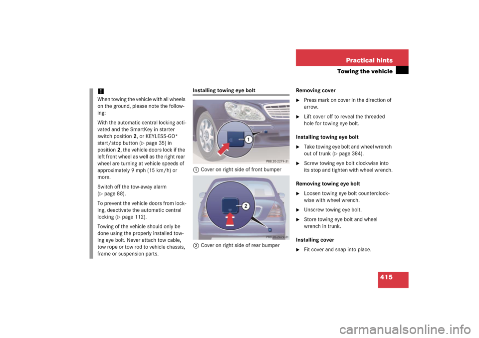
Installing towing eye bolt
1Cover on right side of front bumper
2Cover on right side of rear bumperRemoving cover
�
Press mark on cover in the direction of
arrow.
�
Lift cover off to reveal the threaded
hole for towing eye bolt.
Installing towing eye bolt
�
Take towing eye bolt and wheel wrench
out of trunk (
�page 384).
�
Screw towing eye bolt clockwise into
its stop and tighten with wheel wrench.
Removing towing eye bolt
�
Loosen towing eye bolt counterclock-
wise with wheel wrench.
�
Unscrew towing eye bolt.
�
Store towing eye bolt and wheel
wrench in trunk.
Installing cover
�
Fit cover and snap into place.
!When towing the vehicle with all wheels
on the ground, please note the follow-
ing:
With the automatic central locking acti-
vated and the SmartKey in starter
switch position2, or KEYLESS-GO*
start/stop button (
�page 35) in
position2, the vehicle doors lock if the
left front wheel as well as the right rear
wheel are turning at vehicle speeds of
approximately 9 mph (15 km/h) or
more.
Switch off the tow-away alarm
(
�page 88).
To prevent the vehicle doors from lock-
ing, deactivate the automatic central
locking (
�page 112).
Towing of the vehicle should only be
done using the properly installed tow-
ing eye bolt. Never attach tow cable,
tow rope or tow rod to vehicle chassis,
frame or suspension parts.
Page 418 of 481
417 Practical hintsFuses
Fuse boxes in passenger compartment
There are two fuse boxes in the in passen-
ger compartment. One fuse box is located
in the dashboard. An additional fuse box is
located in the rear passenger compart-
ment.
Fuse box in dashboard
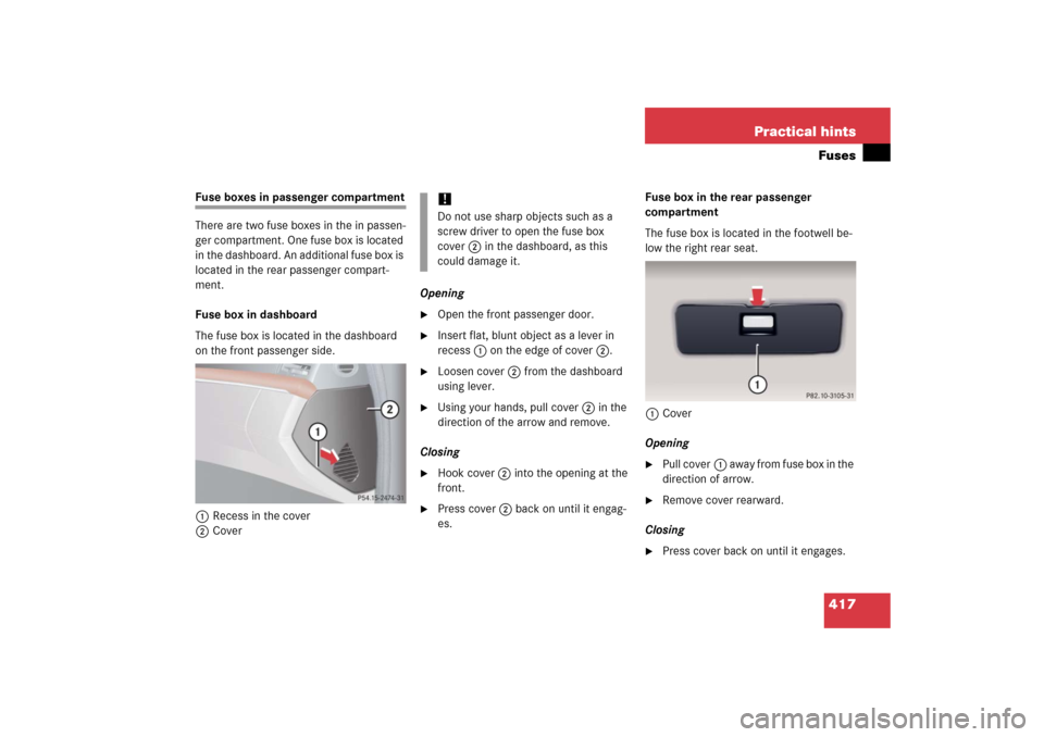
The fuse box is located in the dashboard
on the front passenger side.
1Recess in the cover
2CoverOpening
�
Open the front passenger door.
�
Insert flat, blunt object as a lever in
recess1 on the edge of cover2.
�
Loosen cover2 from the dashboard
using lever.
�
Using your hands, pull cover2 in the
direction of the arrow and remove.
Closing
�
Hook cover2 into the opening at the
front.
�
Press cover2 back on until it engag-
es.Fuse box in the rear passenger
compartment
The fuse box is located in the footwell be-
low the right rear seat.
1Cover
Opening
�
Pull cover1 a w a y f r o m f u s e b o x i n t h e
direction of arrow.
�
Remove cover rearward.
Closing
�
Press cover back on until it engages.
!Do not use sharp objects such as a
screw driver to open the fuse box
cover2 in the dashboard, as this
could damage it.
Page 423 of 481
422 Technical dataIdentification labels1Certification label (below driver’s door
latch)2Vehicle Identification Number (VIN)
(below right rear passenger seat)3Engine number (engraved on engine)
4VIN, visible (lower edge of windshield)
5Emission control information label,
includes both federal and California
certification exhaust emission
standards
6Vacuum line routing diagram label
iWhen ordering parts, please specify
vehicle identification and engine num-
bers.
Page 427 of 481
426 Technical dataRims and tires
!
Only use tires which have been specifi-
cally developed for your vehicle and
tested and approved by
Mercedes-Benz. Tires approved by
Mercedes-Benz are developed to pro-
vide best possible performance in con-
junction with the driving safety
systems on your vehicle such as ABS or
ESP
®. Tires specially developed for
your vehicle and tested and approved
by Mercedes-Benz can be identified by
finding the following on the tire’s side-
wall:
�
MO = M
ercedes-Benz O
riginal
equipment tires
Using tires other than those approved
by Mercedes-Benz may result in dam-
age that is not covered by the
Mercedes-Benz Limited Warranty.
!Using tires other than those approved
by Mercedes-Benz can have detrimen-
tal effects, such as�
poor handling characteristics
�
increased noise
�
increased fuel consumption
Moreover, tires and rims not approved
by Mercedes-Benz may, under load,
exhibit dimensional variations and dif-
ferent tire deformation characteristics
that could cause them to come into
contact with the vehicle body or axle
parts. Damage to the tires or the vehi-
cle may be the result.
iFurther information on tires and rims is
available at any authorized
Mercedes-Benz Center. A placard with
the recommended tire inflation pres-
sures is located on the driver’s door
B-pillar (
�page 300). Some vehicles
may have supplemental tire inflation
pressure information for driving at high
speeds (�page 307) or for vehicle
loads less than the maximum loaded
vehicle condition (
�page 313). If such
information is provided, it can be found
on the placard located on the inside of
the fuel filler flap. The tire inflation
pressure should be checked regularly
and should only be adjusted on cold
tires. Follow tire manufacturer’s main-
tenance recommendation included
with vehicle.