Page 393 of 481

392 Practical hintsReplacing SmartKey batteriesIf the batteries in the SmartKey or the
SmartKey with KEYLESS-GO* are dis-
charged, the vehicle can no longer be
locked or unlocked. It is recommended to
have the batteries replaced at an autho-
rized Mercedes-Benz Center.
Batteries contain materials that can harm
the environment if disposed of improperly.
Recycling of batteries is the preferred
method of disposal. Many states require
sellers of batteries to accept old batteries
for recycling.
SmartKey
Replacement batteries: Lithium, type
CR 2025 or equivalent.�
Remove the mechanical key out of the
SmartKey (
�page 388).1Mechanical key
2Slide
3Battery compartment
�
Insert mechanical key1 in the direc-
tion of arrow in side opening.
�
Using mechanical key1, push gray
slide 2 to unlatch battery compart-
ment 3.
�
Pull battery compartment3 out of the
housing in the direction of arrow.
Warning!
G
Batteries contain poisonous and corrosive
substances. Therefore keep the batteries
out of reach of children.
If a battery is swallowed, seek medical help
immediately.
iWhen inserting the batteries, make
sure they are clean and free of lint.iThe required replacement batteries are
available at any authorized
Mercedes-Benz Center.iWhen changing batteries, always re-
place both batteries.
Page 394 of 481

393 Practical hints
Replacing SmartKey batteries
4Battery
5Contact spring�
Remove the batteries4 in the direc-
tion of arrow.
�
Using a lint-free cloth, insert new
batteries4 under the contact
spring5 with the positive terminal (+)
side facing up.
�
Return battery compartment3
(�page 392) into housing until it locks
into place.
�
Slide mechanical key1 (
�page 388)
back into the SmartKey.
�
Check the operation of the SmartKey.
SmartKey with KEYLESS-GO*
Replacement battery: Lithium, type
CR 2025 or equivalent.�
Remove the mechanical key out of the
SmartKey with KEYLESS-GO
(�page 388).
�
Remove battery compartment3
(�page 392) out of the housing.
1Battery
2Tilt battery up
3Mechanical key
�
Using mechanical key3, apply pres-
sure to position2.
Battery1 tilts up slightly.
�
Pull out battery1 in the direction of
arrow.
�
Using a lint-free cloth, insert new
battery1 with the plus (+) side facing
up.
�
Return battery compartment3
(�page 392) into housing until it locks
into place.
�
Slide mechanical key1 (
�page 388)
back into the SmartKey with
KEYLESS-GO.
�
Check the operation of KEYLESS-GO.
Page 399 of 481

398 Practical hintsReplacing bulbsHalogen headlamp�
Press the tab on cover3 and remove
cover.
�
Pull connector7 off of the lamp.
�
Release the retaining springs and take
out the bulb.
�
Insert the new bulb in the socket so
that the base is in the recess on the
lower left.
�
Attach the retaining springs.
�
Insert connector7 into the bulb.
�
Press cover3 onto the housing until
the tab engages.Replacing halogen high beam bulbs
�
Press the tab on cover2 and remove
cover.
�
Pull connector 6 off of the bulb.
�
Apply pressure on the bulb contacts
from above until the bulb releases from
the retaining springs.
�
Remove bulb.
�
Insert the new bulb in the socket with
the marking facing upward.
�
Press the bulb upward on the contacts
until it engages in the retaining springs.
�
Insert connector6 onto the bulb.
�
Press cover2 onto the housing until
the tab engages.Front turn signal lamp bulb
�
Turn bulb socket8 counterclockwise
and pull out.
�
Gently push bulb into socket, turn
counterclockwise and remove.
�
Insert new bulb in socket, push in and
twist clockwise.
�
Reinstall bulb socket in lamp and twist
clockwise until it engages.
Page 400 of 481
399 Practical hints
Replacing bulbs
Parking and standing lamp bulb�
Press the tab on cover2 and remove
cover.
�
Pull out the bulb socket5 with the
bulb.
�
Pull the bulb out of the bulb socket5.
�
Insert a new bulb in the bulb socket5.
�
Reinstall the bulb socket5.
�
Press cover2 onto the housing until
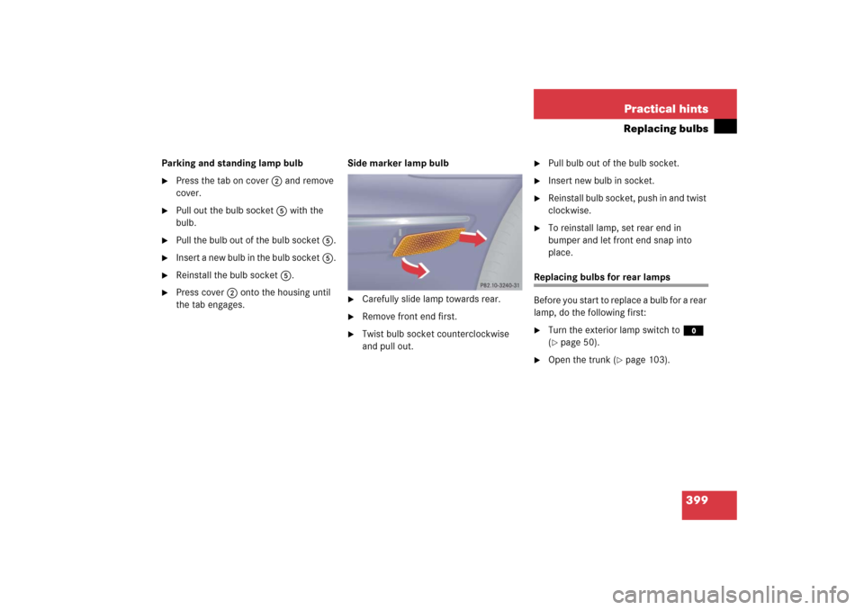
the tab engages.Side marker lamp bulb
�
Carefully slide lamp towards rear.
�
Remove front end first.
�
Twist bulb socket counterclockwise
and pull out.
�
Pull bulb out of the bulb socket.
�
Insert new bulb in socket.
�
Reinstall bulb socket, push in and twist
clockwise.
�
To reinstall lamp, set rear end in
bumper and let front end snap into
place.
Replacing bulbs for rear lamps
Before you start to replace a bulb for a rear
lamp, do the following first:�
Turn the exterior lamp switch to M
(�page 50).
�
Open the trunk (
�page 103).
Page 401 of 481
400 Practical hintsReplacing bulbsTail lamp unitPassenger side1Black socket:
Backup lamp
2Red socket:
Driver’s side: Tail, parking and rear fog
lamp
Passenger side: Tail and parking lamp
3Red socket:
Tail, standing and parking lamp
4White socket:
Turn signal lamp
�
Driver’s side: Turn the locking knob and
move the trim to the side.
�
Passenger side: Fold the trim to the
side.
�
Turn bulb socket counterclockwise and
pull out.
�
Gently twist bulb counterclockwise and
pull out of bulb holder.
�
Insert new bulb into the holder and turn
it clockwise.
�
Reinstall bulb socket.
The bulb socket should audibly click.
�
Driver’s side: Replace the trim and se-
cure with lock.
�
Passenger side: Reinstall the trim. License plate lamp
1Screws
�
Loosen both screws1.
�
Remove the license plate lamp.
�
Replace the bulb.
�
Reinstall the license plate lamp.
�
Retighten screws1.
Page 403 of 481
402 Practical hintsReplacing wiper bladesInstalling wiper blades�
Slide the wiper blade onto wiper arm
until it locks in place
�
Rotate the wiper blade into position
parallel to wiper arm.
�
Fold the wiper arm backward to rest on
the windshield. Make sure you hold
onto the wiper when folding the wiper
arm back.
!Never open the hood when the wiper
arm is folded forward.
Hold on to the wiper when folding the
wiper arm back. If released, the force
of the impact from the tensioning
spring could crack the windshield.
Do not allow the wiper arms to contact
the windshield glass without a wiper
blade inserted.
Make certain that the wiper blades are
properly installed. Improperly installed
wiper blades may cause windshield
damage.
For your convenience, we recommend
that you have this work carried out by
an authorized Mercedes-Benz Center.
Page 405 of 481
.Lifting the vehicle
�
Prevent the ve")
404 Practical hintsFlat tirePreparing the vehicle�
Take vehicle tool kit tray and vehicle
jack out of trunk.
�
Take the spare wheel out of wheel well
(�page 384).Lifting the vehicle
�
Prevent the vehicle from rolling away
by blocking wheels with wheel chocks
(not included) or other sizeable ob-
jects.
When changing wheel on a level surface:
�
Place wheel chocks or other sizeable
suitable objects in front of and one be-
hind the wheel that is diagonally oppo-
site to the wheel being changed.
Always try lifting the vehicle using the jack
on a level surface. However, should cir-
cumstances require you to do so on a hill,
place the wheel chocks or other sizeable
suitable objects as follows:
�
Place wheel chocks or other sizeable
suitable objects on the downhill side
blocking both wheels of the axle not
being worked on.
Warning!
G
The jack is designed exclusively for jacking
up the vehicle at the jack tubes built both
sides of the vehicle. To help avoid personal
injury, use the jack only to lift the vehicle
during a wheel change. Never get beneath
the vehicle while it is supported by the jack.
Keep hands and feet away from the area un-
der the lifted vehicle. Always firmly set park-
ing brake and block wheels before raising
vehicle with jack.
Do not disengage parking brake while the
vehicle is raised. Be certain that the jack is
always vertical (plumb line) when in use, es-
pecially on hills. Always try to use the jack
on level surface. Make sure the jack arm is
fully inserted in the jack tube. Always lower
the vehicle onto sufficient capacity jack-
stands before working under the vehicle.
Page 406 of 481
405 Practical hints
Flat tire
�
Take the two-piece wheel wrench out
of the vehicle tool kit tray. Assemble
wheel wrench.
�
On whee l to b e c hang ed, l oose n but d o
not yet remove the wheel bolts (ap-
proximately one full turn with wrench).
The tube openings are located directly be-
hind the front wheel housings and in front
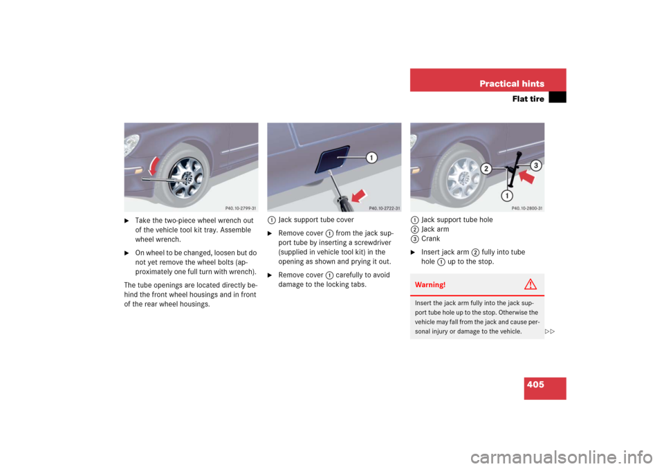
of the rear wheel housings.1Jack support tube cover
�
Remove cover1 from the jack sup-
port tube by inserting a screwdriver
(supplied in vehicle tool kit) in the
opening as shown and prying it out.
�
Remove cover1 carefully to avoid
damage to the locking tabs.1Jack support tube hole
2Jack arm
3Crank
�
Insert jack arm2 fully into tube
hole1 up to the stop.Warning!
G
Insert the jack arm fully into the jack sup-
port tube hole up to the stop. Otherwise the
vehicle may fall from the jack and cause per-
sonal injury or damage to the vehicle.
��