Page 466 of 561
465 Practical hints
Replacing bulbs
�Replacing bulbs
Bulbs
Safe vehicle operation depends on proper
exterior lighting and signaling. It is there-
fore essential that all bulbs and lamp as-
semblies are in good working order at all
times.
Correct headlamp adjustment is extremely
important. Have headlamps checked and
readjusted at regular intervals and when a
bulb has been replaced. See an authorized
Mercedes-Benz Light Truck Center for
headlamp adjustment.
iIf the headlamps or front fog lamps are
fogged up on the inside as a result of
high humidity, driving the vehicle a dis-
tance with the lights on should clear up
the fogging.
iBackup bulbs will be brought into use
when the following lamps malfunction:�
Turn signal lamps
�
Brake lamps
�
Parking lamps
�
Tail lamps
Read and observe messages in the
multifunction display (
�page 442).
Page 467 of 561
466 Practical hintsReplacing bulbsFront lamps Rear lamps
Lamp
Type
1
Parking/standing lamp
W 5 W
2
Turn signal lamp
PY 21 W
3
Additional turn signal
lamp
LED
4
Headlamps:
Low beam
H7 (55W)
Bi-Xenon headlamps*:
Low beam
1
1Vehicles with Bi-Xenon* headlamps: Do not
replace the Bi-Xenon bulbs yourself. Contact an
authorized Mercedes-Benz Light Truck Center.
D2S-35 W
5
Headlamps:
High beam/high beam
flasher
H7 (55W)
Bi-Xenon headlamps*:
High beam/high beam
flasher spot lamp
H7 (55W)
6
Sidemarker lamp
WY 5 W
7
Corner-illuminating
front fog lamp*
H11 (55W)
Lamp
Type
8
High-mounted brake
lamp
LED
9
Tail, brake, and
sidemarker lamp
P 21 W
a
Turn signal lamp
PY 21 W
b
Backup lamp
P 21 W
c
Rear fog lamp (driver’s
side only)
P 21 W
d
License plate lamps
C 5 W
Page 471 of 561
470 Practical hintsReplacing bulbsLow beam and high beam flasher spot
bulbsFront turn signal lamp bulbs
�
Pull bulb socket 1 out of the head-
lamp housing.
�
Pull the turn signal bulb out of bulb
socket 1.
�
Insert the new turn signal bulb into bulb
socket 1.
�
Insert bulb socket 1 into the head-
lamp housing.Parking and standing lamp bulbs
1Bulb socket for parking and standing
lamp
�
Turn bulb socket 1 counterclockwise.
�
Pull bulb socket 1 out of the housing.
�
Pull the bulb out of bulb socket 1.
�
Insert the new parking and standing
lamp bulb into bulb socket 1.
�
Insert bulb socket 1 into the housing.
�
Turn bulb socket 1 clockwise until it
engages.
Warning!
G
Do not remove the low beam/high beam
cover for the Bi-Xenon* headlamp. Because
of high voltage in Bi-Xenon* lamps, it is dan-
gerous to replace the bulb or repair the lamp
and its components. We recommend that
you have such work done by a qualified
technician.
Page 474 of 561
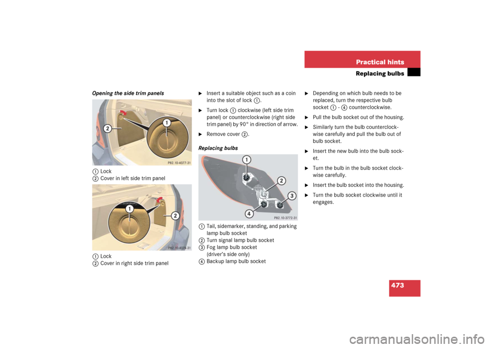
473 Practical hints
Replacing bulbs
Opening the side trim panels
1Lock
2Cover in left side trim panel
1Lock
2Cover in right side trim panel
�
Insert a suitable object such as a coin
into the slot of lock1.
�
Turn lock1 clockwise (left side trim
panel) or counterclockwise (right side
trim panel) by 90° in direction of arrow.
�
Remove cover2.
Replacing bulbs
1Tail, sidemarker, standing, and parking
lamp bulb socket
2Turn signal lamp bulb socket
3Fog lamp bulb socket
(driver’s side only)
4Backup lamp bulb socket
�
Depending on which bulb needs to be
replaced, turn the respective bulb
socket 1 - 4 counterclockwise.
�
Pull the bulb socket out of the housing.
�
Similarly turn the bulb counterclock-
wise carefully and pull the bulb out of
bulb socket.
�
Insert the new bulb into the bulb sock-
et.
�
Turn the bulb in the bulb socket clock-
wise carefully.
�
Insert the bulb socket into the housing.
�
Turn the bulb socket clockwise until it
engages.
Page 479 of 561
.")
478 Practical hintsFlat tire
Preparing the vehicle�
Park the vehicle in a safe distance from
moving traffic on a hard, flat surface
when possible.
�
Turn on the hazard warning flasher
(�page 153).
�
Turn the steering wheel so that the
front wheels are in a straight-ahead
position.
�
Set the parking brake (
�page 65).
�
Set the automatic transmission to P
(�page 197).
Vehicles with SmartKey:
�
Turn off the engine (
�page 66).
�
Remove the SmartKey from the starter
switch.Vehicles with KEYLESS-GO*:
�
Turn off the engine by pressing the
KEYLESS-GO* button once
(�page 66).
�
Open the driver’s door (this puts the
starter switch in position 0, same as
with the SmartKey removed from the
starter switch). The driver’s door then
can be closed again.
�
Have any passenger exit the vehicle at
a safe distance from the roadway.
Warning!
G
The dimensions of the spare wheel are dif-
ferent from those of the road wheels. As a
result, the vehicle handling characteristics
change when driving with a spare wheel
mounted. Adapt your driving style accord-
ingly.
The spare wheel is for temporary use only.
When driving with spare wheel mounted,
ensure proper tire inflation pressure and do
not exceed a vehicle speed of
50 mph (80 km/ h).
Drive to the nearest Mercedes-Benz Light
Truck Center as soon as possible to have the
spare wheel replaced with a regular road
wheel.
Never operate the vehicle with more than
one spare wheel mounted.
Do not switch off the ESP
® with a spare
wheel mounted.
iOpen doors only when conditions are
safe to do so.
Page 480 of 561
.
�
Take the wheel wrench and the vehicle
jack from the vehicle tool kit
(�")
479 Practical hints
Flat tire
Mounting the spare wheel
Preparing the vehicle�
Prepare the vehicle as described
(�page 478).
�
Take the wheel wrench and the vehicle
jack from the vehicle tool kit
(�page 455).
�
Take the spare wheel from the wheel
well under the cargo compartment
floor (
�page 458).Lifting the vehicle
�
Prevent the vehicle from rolling away
by blocking wheels with wheel chocks
or other sizable objects.
One wheel chock is included with the
vehicle tool kit (
�page 455).
When changing wheel on a level surface:
�
Place the wheel chock in front of and
another sizable object behind the
wheel that is diagonally opposite to the
wheel being changed.
Always try lifting the vehicle using the jack
on a level surface. However, should cir-
cumstances require you to do so on a hill,
place the wheel chock and another sizable
object as follows:
�
Place the wheel chock and another
sizable object on the downhill side
blocking both wheels of the axle not
being worked on.
Warning!
G
The jack is designed exclusively for jacking
up the vehicle at the jack take-up brackets
built into both sides of the vehicle. To help
avoid personal injury, use the jack only to lift
the vehicle during a wheel change. Never
get beneath the vehicle while it is supported
by the jack. Keep hands and feet away from
the area under the lifted vehicle. Always
firmly set parking brake and block wheels
before raising vehicle with jack.
Do not disengage parking brake while the
vehicle is raised. Be certain that the jack is
always vertical (plumb line) when in use,
especially on hills. Always try to use the jack
on level surface. Make sure the jack arm is
fully seated in the jack take-up bracket.
Always lower the vehicle onto sufficient
capacity jackstands before working under
the vehicle.
Page 491 of 561

�
Set the automatic position to P
(�page 199).
�
Firmly depress the parking brake
(�page 65).
�
Turn off the engine (
�page 66).
�
Leave the ignition")
490 Practical hintsBatteryStep 1 (Disconnecting)
�
Set the automatic position to P
(�page 199).
�
Firmly depress the parking brake
(�page 65).
�
Turn off the engine (
�page 66).
�
Leave the ignition switched on
(�page 38).
�
Switch off all electrical consumers.
�
Read and observe safety instructions
and precautions (
�page 487).
�
Open the front passenger door.
�
Move the front passenger seat to the
most rearward position (
�page 43).Step 2 (Disconnecting)
1Seat rail covers, front right
2Seat rail covers, front left
�
Pull off right seat rail cover 1 in direc-
tion of arrow.
�
Pull left seat rail cover 2 in direction
of arrow as far as it will go.
Left seat rail cover 2 cannot be re-
moved.
iWith a disconnected battery you will no
longer be able to turn the SmartKey in
the starter switch and pressing the
KEYLESS-GO* start/stop button will
have no effect.iIf your battery is discharged, the vehi-
cle must be jump started (
�page 496)
using the jump start contacts in the
engine compartment, or an accessory
battery charge unit* approved by
Mercedes-Benz must be connected
using the jump start contacts in the
engine compartment (see separate
instructions for the accessory battery
charge unit*) before any of the follow-
ing steps can be performed. If the bat-
tery cannot be jumped or charged,
please contact an authorized
Mercedes-Benz Light Truck Center.
iOpen doors only when conditions are
safe to do so.
Page 498 of 561
 terminal
2Positive (+) terminal �
Make sure the two vehicles do not
touch.
�
Turn off a")
497 Practical hints
Jump starting
The jump-start contacts are located in the
engine compartment.
1Negative (-) terminal
2Positive (+) terminal �
Make sure the two vehicles do not
touch.
�
Turn off all electrical consumers.
�
Apply parking brake.
�
Set automatic transmission to
positionP.
�
Open the hood (
�page 345).
�
Open cover of positive terminal 2.
1Negative terminal of discharged
battery
2Positive terminal of discharged battery
3Negative terminal of charged battery
4Positive terminal of charged battery
�
Connect positive terminals2 and 4
with the jumper cable. Clamp cable to
charged battery 4 first.
�
Start engine of the vehicle with the
charged battery and run at idle speed.
�
Connect negative terminals1 and 3
of the batteries with the jumper cable.
Clamp cable to charged battery 3
first.
�
Start the engine of the disabled vehi-
cle.
Warning!
G
Keep flames or sparks away from battery.
Do not smoke.
Observe all safety instructions and precau-
tions when handling automotive batteries.
!Never invert the terminal connections!

Bi-Xenon h")