Page 134 of 561

133 Controls in detailSeats
When entering the vehicle, with the
easy-entry/exit feature activated, the
steering wheel or, depending on your se-
lection, the steering wheel and driver’s
seat will return to their last set memory po-
sition or a factory-set maximum forward
position when you�
close the driver’s door with the ignition
switched on
�
insert the SmartKey into the starter
switch or press the KEYLESS-GO*
start/stop button (
�page 40) once
with the driver’s door closed
iIf the current position for the steering
wheel is in the uppermost tilt position,
the steering wheel will no longer be
able to move upward when the
easy-entry/exit feature is activated.
If the current seat position falls into a
factory-set position range and the sys-
tem recognizes the current seat posi-
tion to be rearward enough for easy
entry and exit, the driver’s seat will not
move to the rear when the
easy-entry/exit feature is activated.
iFor safety reasons, the driver’s seat will
not return to its last set position with
the easy-entry/exit feature activated if
the system recognizes the last set posi-
tion as an extreme forward position. In-
stead, the driver’s seat will remain at or
move to a factory-set maximum for-
ward position. To again fully return the
driver’s seat to your last set position or
to memory position, adjust the seat to
the desired position or press and hold
the respective memory position button
(�page 145).
iVehicles with memory function*:
The steering wheel and seat position is
stored into memory when you�
switch off the ignition (
�page 38)
�
allocate the current position steer-
ing wheel and seat position to a cer-
tain memory position button
(�page 145)
Page 137 of 561

136 Controls in detailSeatsLumbar support
The curvature of the driver’s seat can be
adjusted to help enhance lower back sup-
port and seating comfort.
The lever for lumbar support adjustment is
located on the right hand side of the
driver’s seat backrest.
1Adjustment lever�
Move adjustment lever 1 in direction
of arrows until you have reached a
comfortable seating position.
Multicontour seat*
The multicontour seat has an extendable
seat cushion and inflatable air chambers
built into the backrest to provide additional
lumbar and side support.
The seat cushion depth, seat backrest
cushion-height and curvature can be con-
tinuously varied with switches on the in-
side of each front seat base after the
ignition is switched on (
�page 38).
1Seat cushion depth
2Backrest side bolsters
3Backrest center
4Backrest bottom
�
Switch on the ignition (
�page 38).
Seat cushion depth
�
Adjust the seat cushion depth to the
length of your upper leg with
switch1.
Backrest contour
�
Adjust the contour of the seat backrest
to the desired position with switch
æ orç.
�
Move the seat backrest support to the
bottom with button4 or to the center
with button3.
Backrest side bolsters
�
Adjust the side bolsters so that they
provide good lateral support with
switch2.
Page 143 of 561
.
Switching on
�
Press switch1.
Three red indicator lamps2 in the
switch come on.
�
C")
142 Controls in detailSeats
1Seat heating switch, front seats
2Indicator lamps�
Switch on the ignition (
�page 38).
Switching on
�
Press switch1.
Three red indicator lamps2 in the
switch come on.
�
Continue pressing switch1 until
desired seat heating level is reached.
Warning!
G
The seat heating switches off automatically.
However, should a malfunction occur and
the automatic switch-off function fail, the
seat cushion and seat backrest can become
very hot. This may cause burns.
Always be aware of the selected heating
level for all seats equipped with seat heat-
ing. Vehicle occupants, especially occu-
pants who suffer from spinal cord injuries or
spinal cord disorders, may not notice that
the seat heating is switched on and/or if the
seat heating does not switch off as intend-
ed. To reduce the risk of burns and personal
injury, take notice of wether and how the
seat heaters are operational and switch off
manually if necessary.
Leveloff
No indicator lamps on.
1
One indicator lamp on.
The seat heating automatically
switches off after approximately
20 minutes.
2
Two indicator lamps on.
The seat heating automatically
switches to level 1 after approxi-
mately 10 minutes.
3
Three indicator lamps on.
The seat heating automatically
switches to level 2 after approxi-
mately 5 minutes.
Page 146 of 561

145 Controls in detail
Memory function*
The memory button and stored position
buttons are located on the entry side of
each front seat base.
MMemory button
1, 2, 3Stored positions�
Switch on the ignition (
�page 38).
or
�
Open the respective door.
Storing positions into memory�
Adjust the seats, steering wheel and
exterior rear view mirrors to the de-
sired position (
�page 42).
�
Press memory buttonM.
�
Release memory button M and press
stored position 1, 2 or 3 within
3 seconds.
All settings are stored to the selected
position.
Recalling positions from memory�
Press and hold memory position
button1,2 or3 until the seat, steering
wheel and exterior rear view mirrors
have fully moved to the stored posi-
tions.!Do not operate the power seats using
memory button M if the seat backrest
is in an excessively reclined position.
Doing so could cause damage to front
or rear seats.
First move seat backrest to an upright
position.iReleasing the memory position button
stops movement to the stored posi-
tions immediately.
Page 147 of 561

146 Controls in detailMemory function*Storing exterior rear view mirror parking position
For easier parking, you can adjust the
passenger-side exterior rear view mirror so
that you can see the right rear wheel as
soon as you engage reverse gearR.
You can switch the parking position fea-
ture on and off in the control system.
For information on activating the parking
position feature, see “Setting parking posi-
tion for exterior rear view mirror*”
(�page 190).1Adjustment button
2Passenger-side exterior rear view mir-
ror
MMemory button
�
Stop the vehicle in a safe location.
�
Switch on the ignition (
�page 38).
�
Press button2 on the door control
panel.
The passenger-side exterior rear view
mirror is selected. The indicator lamp
on button2 comes on.
�
Adjust the passenger-side exterior rear
view mirror with button1 so that you
see the rear wheel and the road curb.
�
Press memory buttonM.
�
Within 3 seconds, press adjustment
button1 once more.
The parking position is stored if the
mirror does not move.iIf the mirror does move, repeat the
above steps. After the setting is stored,
you can move the mirror again.
Page 155 of 561
154 Controls in detailLightingSwitching on hazard warning flasher�
Press hazard warning flasher
switch1.
All turn signals are flashing.
Switching off hazard warning flasher
�
Press hazard warning flasher switch1
again.
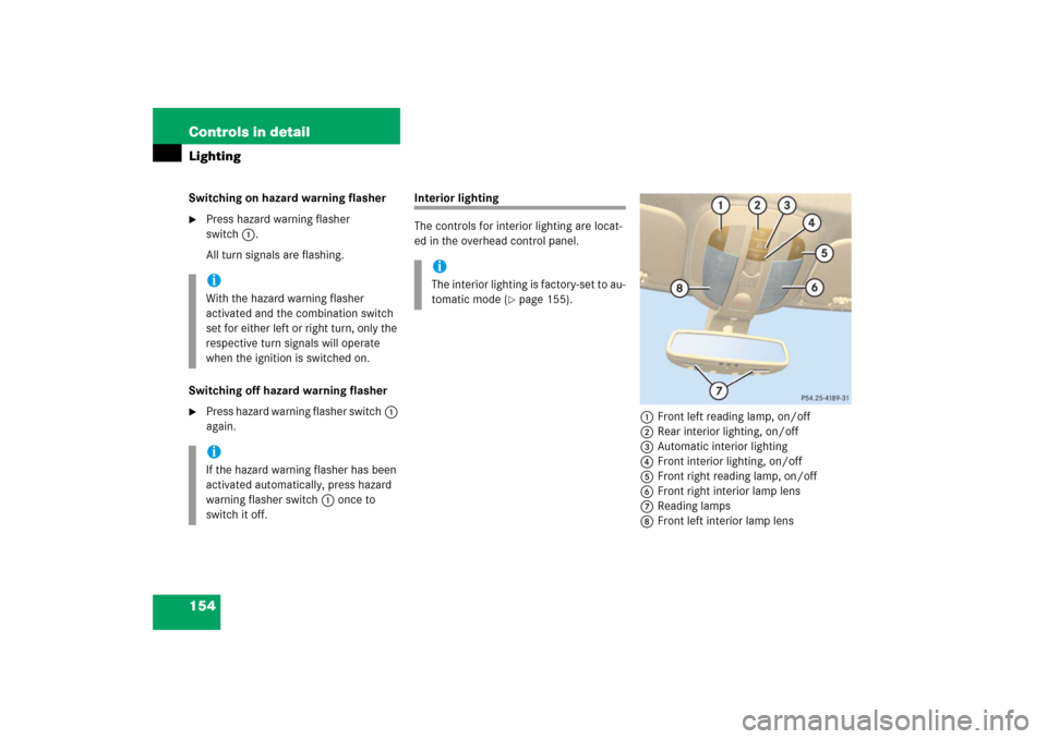
Interior lighting
The controls for interior lighting are locat-
ed in the overhead control panel.
1Front left reading lamp, on/off
2Rear interior lighting, on/off
3Automatic interior lighting
4Front interior lighting, on/off
5Front right reading lamp, on/off
6Front right interior lamp lens
7Reading lamps
8Front left interior lamp lens
iWith the hazard warning flasher
activated and the combination switch
set for either left or right turn, only the
respective turn signals will operate
when the ignition is switched on.iIf the hazard warning flasher has been
activated automatically, press hazard
warning flasher switch1 once to
switch it off.
iThe interior lighting is factory-set to au-
tomatic mode (
�page 155).
Page 159 of 561
.
1Dimming instrument cluster illumina-
tion
2Reset button
3Bri")
158 Controls in detailInstrument clusterFor a full view illustration of the instrument
cluster, see “Instrument cluster”
(�page 24).
1Dimming instrument cluster illumina-
tion
2Reset button
3Brightening instrument cluster illumi-
nationThe instrument cluster is activated when
you
�
open a door
�
switch on the ignition (
�page 38)
�
press reset button 2
�
switch on the exterior lamps
(�page 147)
You can modify the instrument cluster set-
tings in the instrument cluster submenu of
the control system (
�page 178).
Instrument cluster illumination
Use button 1 or 3 to adjust the illumina-
tion brightness for the instrument cluster.
To brighten illumination�
Press and hold button 3 until the
desired level of illumination is reached.
To dim illumination
�
Press and hold button 1 until the
desired level of illumination is reached.
Warning!
G
If the instrument cluster or the multifunction
display, or both, are inoperative or malfunc-
tioning, warning messages will not be re-
layed when potential danger exists. This
may cause you and others to be unaware of
certain risks, which may result in an acci-
dent and/or personal injury.
Contact the nearest authorized
Mercedes-Benz Light Truck Center as soon
as possible.
iThe instrument cluster illumination is
dimmed or brightened automatically to
suit ambient light conditions.
The instrument cluster illumination will
also be adjusted automatically when
you switch on the vehicle’s exterior
lamps.
Page 178 of 561

177 Controls in detail
Control system
The table below shows what settings can
be changed within the various menus.
Detailed instructions on making individual
settings can be found on the following
pages.INSTRUMENT CLUSTER
TIME/DATE
LIGHTING
VEHICLE
CONVENIENCE
Selecting speedometer display
mode
Setting the time
(hours)
Setting daytime running
lamp mode (USA only)
Calling up the compass
Activating
easy-entry/exit feature*
Selecting language
Setting the time
(minutes)
Setting locator lighting
Compass adjustment
Setting parking position
for exterior rear view
mirror
Selecting display (digital
speedometer or outside
temperature) for status indicator
Setting the date
(month)
Setting night security
illumination
Compass calibration
Setting fold-in function
for exterior rear view
mirrors
Setting the date
(day)
Setting interior lighting
delayed shut-off
Setting which display to
appear with ignition
switched off
Setting the date
(year)
Setting automatic
lockingLimiting opening height
of tailgate*