Page 498 of 561

497 Practical hints
Jump starting
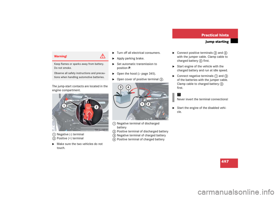
The jump-start contacts are located in the
engine compartment.
1Negative (-) terminal
2Positive (+) terminal �
Make sure the two vehicles do not
touch.
�
Turn off all electrical consumers.
�
Apply parking brake.
�
Set automatic transmission to
positionP.
�
Open the hood (
�page 345).
�
Open cover of positive terminal 2.
1Negative terminal of discharged
battery
2Positive terminal of discharged battery
3Negative terminal of charged battery
4Positive terminal of charged battery
�
Connect positive terminals2 and 4
with the jumper cable. Clamp cable to
charged battery 4 first.
�
Start engine of the vehicle with the
charged battery and run at idle speed.
�
Connect negative terminals1 and 3
of the batteries with the jumper cable.
Clamp cable to charged battery 3
first.
�
Start the engine of the disabled vehi-
cle.
Warning!
G
Keep flames or sparks away from battery.
Do not smoke.
Observe all safety instructions and precau-
tions when handling automotive batteries.
!Never invert the terminal connections!
Page 500 of 561

499 Practical hints
Towing the vehicle
�Towing the vehicle
Mercedes-Benz recommends that the
vehicle be transported with all wheels off
the ground using flatbed or appropriate
wheel lift/dolly equipment. This method is
preferable to other types of towing.When circumstances do not permit the
recommended towing methods, the
vehicle may be towed with all wheels on
the ground only so far as necessary to have
the vehicle moved to a safe location where
the recommended towing methods can be
employed.
!Use flatbed or wheel lift/dolly equip-
ment, with the SmartKey in starter
switch turned to position0.
Do not tow with sling-type equipment.
Towing with sling-type equipment over
bumpy roads will damage radiator and
supports.
To prevent damage during transport,
do not tie down vehicle by its chassis or
suspension parts. Use the towing eyes.
Switch off the ESP
® (�page 101),
tow-away alarm (
�page 107) and the
automatic central locking
(
�page 130).
Do not tow-start the vehicle.
!Do not tow with one axle raised. Doing
so could damage the transfer case,
which is not covered by the
Mercedes-Benz Limited Warranty.
All wheels must be on or off the ground.
Observe instructions for towing the ve-
hicles with all wheels on the ground.
!When towing the vehicle with all wheels
on the ground, the automatic transmis-
sion must be in positionN and the
SmartKey must be in starter switch
position2.
When towing the vehicle with all wheels
on the ground, the vehicle may be
towed only for distances up to 30 miles
(50 km) and at a speed not to exceed
30 mph (50 km / h).
If the vehicle is towed with the front
axle raised (observe instructions re-
garding flexible drive shaft), the engine
must be shut off (SmartKey in starter
switch position1). Otherwise, the
4-ETS may become engaged which may
cause loss of towing control.
Page 501 of 561

500 Practical hintsTowing the vehicle
!
To be certain to avoid additional dam-
age to the vehicle powertrain, however
you should observe the following:�
With damage to the front axle�
raise front axle
�
remove flexible drive shaft be-
tween rear axle and transfer
case
�
With damage to the rear axle�
raise rear axle
�
tow vehicle with wheel lift or
dolly placed under front wheels
�
With damage to the transfer case�
remove flexible drive shaft to
the drive axles
Always install new self-locking nuts
when reinstalling flexible drive shaft.
Warning!
G
If circumstances require towing the vehicle
with all wheels on the ground, always tow
with a tow bar if:�
the engine will not run
�
there is a malfunction in the power
supply or in the vehicle’s electrical sys-
tem
Prior to towing the vehicle with all wheels on
the ground, make sure the SmartKey is in
starter switch position2.
If the SmartKey is left in starter switch
position0 for an extended period of time, it
can no longer be turned in the switch. In this
case, the steering is locked. To unlock,
remove SmartKey from starter switch and
reinsert.
Warning!
G
With the engine not running, there is no
power assistance for the brake and steering
systems. In this case, it is important to keep
in mind that a considerably higher degree of
effort is necessary to brake and steer the
vehicle. Adapt your driving accordingly.iTo signal turns while being towed with
hazard warning flasher in use, turn the
SmartKey in starter switch to
position2 and activate combination
switch for left or right turn signal in
usual manner – only the selected turn
signal will operate.
Upon canceling the turn signal, the
hazard warning flasher will operate
again.
Page 505 of 561

504 Practical hintsFusesMain fuse box
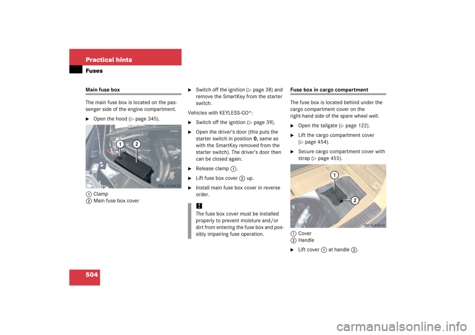
The main fuse box is located on the pas-
senger side of the engine compartment.�
Open the hood (
�page 345).
1Clamp
2Main fuse box cover
�
Switch off the ignition (
�page 38) and
remove the SmartKey from the starter
switch.
Vehicles with KEYLESS-GO*:
�
Switch off the ignition (
�page 39).
�
Open the driver’s door (this puts the
starter switch in position 0, same as
with the SmartKey removed from the
starter switch). The driver’s door then
can be closed again.
�
Release clamp1.
�
Lift fuse box cover2 up.
�
Install main fuse box cover in reverse
order.
Fuse box in cargo compartment
The fuse box is located behind under the
cargo compartment cover on the
right-hand side of the spare wheel well.�
Open the tailgate (
�page 122).
�
Lift the cargo compartment cover
(�page 454).
�
Secure cargo compartment cover with
strap (
�page 455).
1Cover
2Handle
�
Lift cover1 at handle 2.
!The fuse box cover must be installed
properly to prevent moisture and/or
dirt from entering the fuse box and pos-
sibly impairing fuse operation.
Page 508 of 561
507 Technical data
Parts service
Warranty coverage
Identification labels
Layout of poly-V-belt drive
Engine
Rims and tires
Electrical system
Main Dimensions
Weights
Fuels, coolants, lubricants, etc.
Page 511 of 561
510 Technical dataIdentification labels1Certification label (on driver’s B-pillar)
Example certification label R 5002Paintwork code
3Vehicle Identification Number (VIN)
The vehicle identification number (VIN) is
also embossed underneath the passen-
ger-side seat in the second seat row.4Second-row seat
5Carpet
6Vehicle Identification Number (VIN)
�
Move second-row seat 4 on passen-
ger side to the rear as far as possible
(�page 137).
�
Fold carpet 5 in direction of arrow.
You may have to cut the perforated car-
pet using a sharp object, e. g. a knife.
iData shown on certification label are
for illustration purposes only. These
data are specific to each vehicle and
may vary from data shown in the illus-
tration. Refer to certification label on
vehicle for actual data specific to your
vehicle.
iWhen ordering parts, please specify
vehicle identification and engine num-
ber.
Page 512 of 561
511 Technical data
Identification labels
7Vacuum line routing diagram label
8Emission control information label,
includes both federal and California
certification exhaust emission stan-
dards
9VIN, visible (lower edge of windshield)
aEngine number (engraved on engine)
Page 514 of 561

513 Technical data
Engine
�Engine
Model
R 350 (251.165
1)
1The quoted data apply only to the standard vehicle. See an authorized Mercedes-Benz Light Truck Center for the corresponding data of all special bodies and special
equipment.
R 500 (251.175)
1
Engine
272
113
Mode of operation
4-stroke engine, gasoline injection
4-stroke engine, gasoline injection
No. of cylinders
6
8
Bore
3.66 in (92.90 mm)
3.82 in (97.00 mm)
Stroke
3.39 in (86.00 mm)
3.31 in (84.00 mm)
Total piston displacement
213 cu in (3 498 cm
3)
303cuin (4966cm
3)
Compression ratio
10.7:1
10:1
Output acc. to SAE J 1349
268 hp / 6 000 rpm
2
(200 kW /6 000 rpm)
2Premium fuel required. Performance may vary with fuel octane rating.
302 hp / 5 600 rpm
2
(225 kW / 5 600 rpm)
Maximum torque acc. to SAE J 1349
258 lb-ft / 2 400 - 5 000 rpm
(350 Nm / 2 400 - 5 000 rpm)
339 lb-ft / 2 700 - 4 750 rpm
(460 Nm / 2 700 - 4 750 rpm)
Maximum engine speed
6500 rpm
6 300 rpm
Firing order
1-4-3-6-2-5
1-5-4-2-6-3-7-8
Poly-V-belt
2 404 mm
2 370 mm