Page 26 of 539

25 At a glance
Instrument cluster
Item
Page
1
LLeft turn signal
indicator lamp
2
To dim instrument cluster
illumination
148
3
Reset button for:Adjusting instrument cluster
illumination
148
4
Multifunction display with:Trip odometer
150
Main odometer
150
5
To brighten instrument clus-
ter illumination
148
6
KRight turn signal
indicator lamp
7
Tachometer with:
388
Item
Page
1Supplemental
Restraint System
(SRS) indicator lamp
390
?Engine malfunction
indicator lamp,
USA only
385
±Engine malfunction
indicator lamp,
Canada only
385
AHigh beam headlamp
indicator
54
8
Fuel gauge with:Fuel tank reserve warning
lamp
388
9
Multifunction display
with:Outside temperature display
150
Gear position indicator
185
Item
Page
a
Clock
b
Speedometer with:-Antilock Brake Sys-
tem (ABS) indicator
lamp
382
;Brake warning lamp,
USA only
383
3Brake warning lamp,
Canada only
383
vESP
® warning lamp
387
lDistance warning
lamp
Warning lamp without
function. It illuminates when
the ignition is on. It should
go out when the engine is
running.HCombination low tire
pressure/TPMS mal-
function telltale*
391
Page 166 of 539
 for status display�
Move the selection marker with
theæ orç button to the
Instr.
cluster
submenu.")
165 Controls in detail
Control system
Selecting display (speed display or out-
side temperature) for status display�
Move the selection marker with
theæ orç button to the
Instr.
cluster
submenu.
�
Press buttonj ork repeatedly
until you see this message in the dis-
play:
Status line display
.
The selection marker is on the current
setting.
�
Press buttonæ orç to select
whether the speed or the outside tem-
perature appears in the multifunction
display.Time/Date submenu
Access the
Time/Date
submenu via the
Settings
menu. Use the
Time/Date
submenu to change the time and date dis-
play settings. The following functions are
available:Set time (hours)
This function is not available if your vehicle
is equipped with the Modular COMAND
System and navigation module*.
�
Move the selection marker to the Time/Date
submenu using theæ or
çbutton.
�
Press buttonj ork repeatedly
until you see this message in the dis-
play:
Clock, hours
.
The selection marker is on the hour set-
ting.
�
Press buttonæ orç to set the
hour.
Function
Page
Set time (hours)
165
Set time (minutes)
166
Set date (month)
166
Set date (day)
166
Set date (year)
167
iIf your vehicle is equipped with the
Modular COMAND System and naviga-
tion module, see separate COMAND
manual on how to set the date and
time.
Page 167 of 539

This function is not available if your vehicle
is equipped with the Modular COMAND
System and navigation module*.�
Move the selection marker to")
166 Controls in detailControl systemSet time (minutes)
This function is not available if your vehicle
is equipped with the Modular COMAND
System and navigation module*.�
Move the selection marker to the Time/Date
submenu using theæ or
çbutton.
�
Press buttonj ork repeatedly
until you see this message in the dis-
play:
Clock, minutes
.
The selection marker is on the minute
setting.
�
Press buttonæ orç to set the
minutes.Set date (month)
This function is not available if your vehicle
is equipped with the Modular COMAND
System and navigation module*.
�
Move the selection marker to the Time/Date
submenu using theæ or
çbutton.
�
Press buttonj ork repeatedly
until you see this message in the dis-
play:
Date Set month
.
The selection marker is on the month
setting.
�
Press buttonæ orç to set the
month.Set date (day)
This function is not available if your vehicle
is equipped with the Modular COMAND
System and navigation module*.
�
Move the selection marker to the Time/Date
submenu using theæ or
çbutton.
�
Press buttonj ork repeatedly
until you see this message in the dis-
play:
Date Set day
.
The selection marker is on the day set-
ting.
�
Press buttonæ orç to set the
day.
Page 282 of 539

The Tele Aid system consists of three
types of response:�
automatic and manual emergency
�
r")
281 Controls in detail
Useful features
The Tele Aid system
(Tele
matic A
larm I
dentification on
D
emand)
The Tele Aid system consists of three
types of response:�
automatic and manual emergency
�
roadside assistance
�
information
The Tele Aid system is operational provid-
ing that the vehicle’s battery is charged,
properly connected, not damaged and cel-
lular and GPS coverage is available.
The speaker volume of a Tele Aid call can
be adjusted when using the volume control
on the Modular COMAND System or on the
multifunction steering wheel. To raise, turn
the rotary volume control on Modular
COMAND System clockwise or press
buttonæ on the multifunction steering
wheel. To lower, turn the rotary volume
control on Modular COMAND System con-trol counterclockwise or press
buttonç on the multifunction steering
wheel.
�
To activate, press the SOS button, the
Roadside Assistance button• or
the Information button¡, depend-
ing on the type of response required.iThe SOS button is located in the over-
head control panel.
The Roadside Assistance button•
and the Information button¡ are
located below the center armrest
cover.!The Tele Aid system utilizes the cellular
network for communication and the
GPS (G
lobal P
ositioning S
ystem) satel-
lites for vehicle location. If either of
these signals are unavailable, the
Tele Aid system may not function and if
this occurs, assistance must be sum-
moned by other means.
iWhen a Tele Aid call has been initiated,
the Modular COMAND System audio is
muted and the selected mode (radio,
CD etc.) pauses. The optional cellular
phone (if installed) inserted in cradle
switches off. If you must use this
phone, we recommend that you use it
only with the vehicle at a standstill in a
safe location. Remove the phone from
the cradle and place the call. The navi-
gation* system (if engaged) will contin-
ue to run. The display in the instrument
cluster is available for use, and spoken
commands are only available by press-
ing the RPT button on the Modular
COMAND System. A pop-up window
will appear in the Modular COMAND
System display to indicate that a Tele
Aid call is in progress. After the TeleAid
call has ended, the optional cellular
phone inserted in the cradle switches
on again. A PIN entry might be neces-
sary.
Page 325 of 539

324 OperationAt the gas station�
Replace the fuel cap by turning it
clockwise until it audibly engages.
�
Close the fuel filler flap.
Check regularly and before a long trip�
Open the hood (
�page 326).
Example ML 5001Brake fluid
2Coolant level
3Windshield washer system and
headlamp cleaning system*
Engine oil level
For more information on engine oil, see
“Engine oil” (
�page 327).Brake fluid
Coolant
For normal replenishing, use water (pota-
ble water quality).
For more information, see “Coolant level”
(
�page 332) and see “Fuels, coolants, lu-
bricants, etc.” (
�page 493).
iOnly use premium unleaded gasoline
with a minimum Posted Octane Rating
of 91 (average of 96 RON/86 MON).
Information on gasoline quality can
normally be found on the fuel pump.
For more information on gasoline, see
the Factory Approved Service Products
pamphlet.iLeaving the engine running and the fuel
cap open can cause the yellow engine
malfunction indicator lamp
?(USA only), ±(Canada only)
to illuminate.
For more information, see “Practical
hints” (
�page 385).
!If you find that the brake fluid in the
brake fluid reservoir has fallen to the
minimum mark or below, have the
brake system checked for brake pad
thickness and leaks immediately. Noti-
fy an authorized Mercedes-Benz Light
Truck Center immediately. Do not add
brake fluid as this will not solve the
problem. For more information, see
“Practical hints” (
�page 381).
��
Page 433 of 539
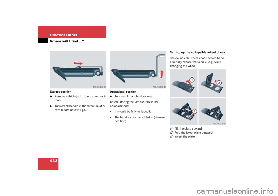
432 Practical hintsWhere will I find ...?Storage position�
Remove vehicle jack from its compart-
ment.
�
Turn crank handle in the direction of ar-
row as fast as it will go.
Operational position�
Turn crank handle clockwise.
Before storing the vehicle jack in its
compartment:
�
It should be fully collapsed.
�
The handle must be folded in (storage
position).Setting up the collapsible wheel chock
The collapsible wheel chock serves to ad-
ditionally secure the vehicle, e.g. while
changing the wheel.
1Tilt the plate upward
2Fold the lower plate outward
3Insert the plate
Page 435 of 539
434 Practical hintsWhere will I find ...?�
Loosen retaining screw3 by turning it
counterclockwise.
�
Remove Minispare wheel1.
Use the Minispare wheel only temporarily,
while observing the following restrictions:
�
Do not exceed vehicle speed of
50 mph (80 km/h).
�
Drive to the nearest repair facility to
have the flat tire repaired or replaced
as appropriate.
�
Do not operate vehicle with more than
one Minispare wheel mounted.iPlease comply with the instructions for
“Mounting the spare wheel”
(�page 457).
��
Page 437 of 539

436 Practical hintsUnlocking/locking in an emergencyUnlocking the driver’s door
1Unlocking
2Mechanical key�
Insert the mechanical key2 into the
driver’s door lock until it stops.
�
Turn the mechanical key2 counter-
clockwise to position1.
�
Pull the door handle until the locking
knob moves up (
�page 117).
The driver’s door is unlocked.
�
Pull the door handle again to open the
driver’s door.
Locking the vehicle
If you cannot lock the vehicle using the
SmartKey or KEYLESS-GO*, do the follow-
ing:�
Close the passenger door, the rear
doors and the tailgate.
�
Press the lower part of the central
locking switch in the door control panel
(�page 126).
�
Check to see whether the locking
knobs on the doors have moved down.
�
If necessary push them down manually.
Except for the driver’s door, the vehicle
should now be locked.1Locking
2Mechanical key
�
Remove the mechanical key out of the
SmartKey (
�page 435).
�
Insert the mechanical key2 into the
driver’s door lock until it stops.
�
Turn the mechanical key2 clockwise
to position1.
The driver’s door is locked.