Page 276 of 539
275 Controls in detail
Useful features
Closing cup holder�
Slide cup holder in until it engages.
Removing and reinstalling cup holder
1Cup holder
2Cup holder bridge
�
Hold cup holder at its bridge2 and
pull out bridge in direction of arrow.
�
Pull cup holder1 out in direction of
arrow.
�
Insert the cup holder1 and then in-
sert bridge2.
Armrest in rear seat bench�
Pull the armrest down by its top.
Ashtrays*
Center console ashtray
1Ashtray insert
2Cover plate
Opening the ashtray�
Briefly touch cover plate2.
The ashtray opens automatically.
!Close the cup holder before folding the
armrest upwards.
Page 277 of 539
276 Controls in detailUseful featuresRemoving ashtray insert�
Grip the ashtray insert1 on the sides
and pull it out upwards.
Reinstalling ashtray insert
�
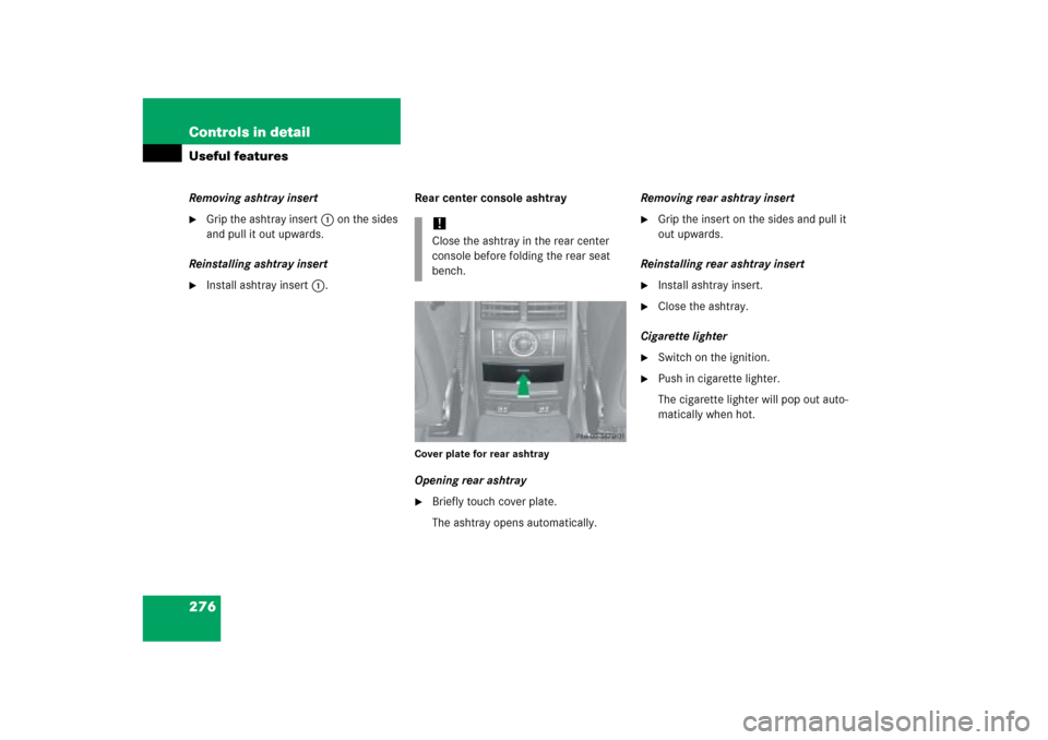
Install ashtray insert1.Rear center console ashtray
Cover plate for rear ashtrayOpening rear ashtray�
Briefly touch cover plate.
The ashtray opens automatically.Removing rear ashtray insert
�
Grip the insert on the sides and pull it
out upwards.
Reinstalling rear ashtray insert
�
Install ashtray insert.
�
Close the ashtray.
Cigarette lighter
�
Switch on the ignition.
�
Push in cigarette lighter.
The cigarette lighter will pop out auto-
matically when hot.
!Close the ashtray in the rear center
console before folding the rear seat
bench.
Page 280 of 539

279 Controls in detail
Useful features
Floormats*
1Retainer pin
2Eyelet
Removing
�
Pull floormat off of retainer pins1.
�
Remove the floormat.
Installing
�
Lay down the floormat.
�
Press the floormat eyelets2 onto re-
tainer pins1.
Telephone*
Radio transmitters, such as a portable tele-
phone or a citizens band unit, should only
be used inside the vehicle if they are con-
nected to an antenna that is installed on
the outside of the vehicle.
The external antenna must be approved by
Mercedes-Benz. Please contact an autho-
rized Mercedes-Benz Light Truck Center
for information on the installation of an ap-
proved external antenna. Refer to the radio
transmitter operation instructions regard-
ing use of an external antenna.
Warning!
G
Whenever you are using floormats, make
sure there is enough clearance and that the
floormats are securely fastened.
Floormats should always be securely fas-
tend using eyelets
2
and retainer pins
1
.
Before driving off, check that the floormats
are securely in place and adjust them if nec-
essary. A loose floormat could slip and
hinder proper functioning of the pedals.
Do not place several floormats on top of
each other as this may impair pedal move-
ment.
iTo install or remove the floormat more
easily, move the driver’s seat or front
passenger seat as far to the rear as
possible (
�page 39).
Warning!
G
Never operate radio transmitters equipped
with a built-in or attached antenna (i.e. with-
out being connected to an external antenna)
from inside the vehicle while the engine is
running. Doing so could lead to a malfunc-
tion of the vehicle’s electronic system, pos-
sibly resulting in an accident and/or serious
personal injury.
Page 383 of 539

382 Practical hintsWhat to do if …Lamps in instrument clusterGeneral information:
If any of the following lamps in the instru-
ment cluster fails to come on during thebulb self-check when switching on the igni-
tion, have the respective bulb checked and
replaced if necessary.Problem
Possible cause
Suggested solution
-
The yellow ABS indicator lamp
comes on while the engine is
running.
ABS has detected a malfunction and has
switched off. The BAS, ESP
®, and 4-ETS are
also switched off (see messages in multifunc-
tion display).
The brake system is still functioning normally
but without the ABS available.
If the ABS control unit is malfunctioning,
other systems such as the navigation
system* or the automatic transmission may
also be malfunctioning.
�
Continue driving with added caution.
Wheels may lock during hard braking,
reducing steering capability.
�
Read and observe messages in the
multifunction display (
�page 395).
�
Have the system checked at an
authorized Mercedes-Benz Light
Truck Center as soon as possible.
Failure to follow these instructions
increases the risk of an accident.
The charging voltage has fallen below
ten volts. The ABS has switched off.
The battery might not be charged sufficiently.
�
Switch off electrical consumers that
are currently not needed, e.g. seat
heating*.
�
If necessary, have the generator
(alternator) and the battery checked.
When the voltage is above this value
again, the ABS is operational again.
Page 399 of 539

398 Practical hintsWhat to do if …Display message
Possible cause
Possible solution
ABS
unavailable
See Operator’s Manual
The ABS was deactivated because of
insufficient power supply. The charg-
ing voltage has fallen below ten
volts.
The brake system is still functioning
normally but without the ABS
available.
�
Switch off electrical consumers that are
currently not needed, e.g. seat heating*.
�
If necessary, have the generator
(alternator) and the battery checked.
When the voltage is above this value again, the
ABS is operational again and the message in
the multifunction display should disappear.
Battery
protection
Convenience functs.
Temporarily
Unavailable
The battery has insufficient voltage
and can no longer supply conve-
nience functions such as the rear
window defroster.
As soon as the on-board voltage is sufficient,
the consumers will switch on again.
Please note:
Convenience Functions
Available again
On-board voltage is sufficient; the
consumers will switch on again.
Cruise
control
Drive to workshop
Cruise control is malfunctioning.
�
Have cruise control checked by an
authorized Mercedes-Benz Light Truck
Center.
DSR
Malfunction
Downhill Speed Regulation is
malfunctioning.
�
Have the Downhill Speed Regulation
checked by an authorized Mercedes-Benz
Light Truck Center.
Page 485 of 539
484 Technical dataIdentification labels1Certification label (on driver’s B pillar)Example certification label ML 5002Paintwork code
3Vehicle identification numberThe vehicle identification number (VIN) is
also embossed on the cross-bar under-
neath the right rear seat.
4Seat cushion
5Floor cover
�
Fold the seat cushion4 forward
(�page 261).
�
Fold floor cover5 in direction of the
arrow.
The VIN is now visible.
6Emission control information label,
includes both federal and California
certification exhaust emission
standards
7Engine number
8Vacuum line routing diagram label
9VIN, visible (lower edge of windshield)
iData shown on certification label exam-
ple is for illustration purpose only. This
data are specific to each vehicle and
may vary from data shown in the illus-
tration below. Refer to certification la-
bel on vehicle for actual data specific to
your vehicle.
Page 503 of 539

502 Technical termsControl system
The control system is used to call up
vehicle information and to change
component settings. Information and
messages appear in the multifunction
display. The driver uses the buttons on
the multifunction steering wheel to
navigate through the system and to ad-
just settings.
Cruise control
Driving convenience system for
automatically maintaining the vehicle
speed set by the driver.
Curb weight
(
�page 365)
DOT
(Department o
f Transportation)
(
�page 365)
DSR
(Downhill S
peed R
egulation)
Driving convenience system for auto-
matically maintaining the vehicle speed
on downhill driving.Engine number
The number set by the manufacturer
and placed on the cylinder block to
uniquely identify each engine
produced.
Engine oil viscosity
Measurement for the inner friction (vis-
cosity) of the oil at different tempera-
tures. The higher the temperature an
oil can tolerate without becoming thin,
or the lower the temperature it can tol-
erate without becoming viscous, the
better the viscosity.
ESP
®(Electronic S
tability Pr
ogram
®)
Improves vehicle handling and direc-
tional stability.
ETD
(E
mergency T
ensioning D
evice)
Device which deploys in certain frontal
and rear collisions exceeding the
system’s threshold to tighten the seat
belts.
->SRSFSS PLUS (Canada vehicles)
(F
lexible S
ervice S
ystem PLUS)
Maintenance service indicator in the
multifunction display that informs the
driver when the next vehicle mainte-
nance service is due. FSS evaluates en-
gine temperature, oil level, vehicle
speed, engine speed, distance driven
and the time elapsed since your last
maintenance service, and calls for the
next maintenance service accordingly.
GAWR
(G
ross A
xle W
eight R
ating)
The GAWR is the maximum permissible
axle weight. The gross vehicle weight
on each axle must never exceed the
GAWR for the front and rear axle indi-
cated on the certification label located
on the driver’s door pillar.
Page 505 of 539

Modular COMAND System
Information and operating center for
vehicle sound and communications
systems, including the radio and the ra-
d")
504 Technical termsMaximum tire inflation pressure
(
�page 366)
Modular COMAND System
Information and operating center for
vehicle sound and communications
systems, including the radio and the ra-
dio and navigation system, as well as
for other optional equipment (CD
changer, telephone, etc.).
Memory function*
Used to store three individual seat,
steering wheel and exterior mirror
positions.
MON
(Motor O
ctane N
umber)
The Motor Octane Number for gasoline
as determined by a standardized meth-
od. It is an indication of a gasoline’s
ability to resist undesired detonation
(knocking). The average of both the
MON (Motor Octane Number) and
->RON (Research Octane Number) is
posted at the pump, also known as
ANTI-KNOCK INDEX.Multifunction display
The display field in the instrument clus-
ter used to present information provid-
ed by the control system.
Multifunction steering wheel
Steering wheel with buttons for operat-
ing the control system.
Normal occupant weight
(
�page 366)
OCS
(Occupant C
lassification S
ystem)
The system automatically turns the
front passenger front air bag on or off
based on the classified occupant size
category determined by weight sensor
readings from the seat.
Overspeed range
Engine speeds within the red marking
on the tachometer dial. Avoid this en-
gine speed range, as it may result in se-
rious engine damage that is not
covered by the Mercedes-Benz Limited
Warranty.Parktronic (Parking assist)*
System which uses visual and acoustic
signals to assist the driver during park-
ing maneuvers.
Poly-V-belt drive
Drives engine-components (alternator,
AC compressor, etc.) from the engine.
Power train
Collective term designating all compo-
nents used to generate and transmit
motive power to the drive axles, includ-
ing
�
Engine
�
Clutch/torque converter
�
Transmission
�
Transfer case
�
Drive shaft
�
Differential
�
Axle shafts/axles

Example certification label ML 5002Paintwork code
3Vehicle identification numberThe vehicle identification number (V")