Page 155 of 539
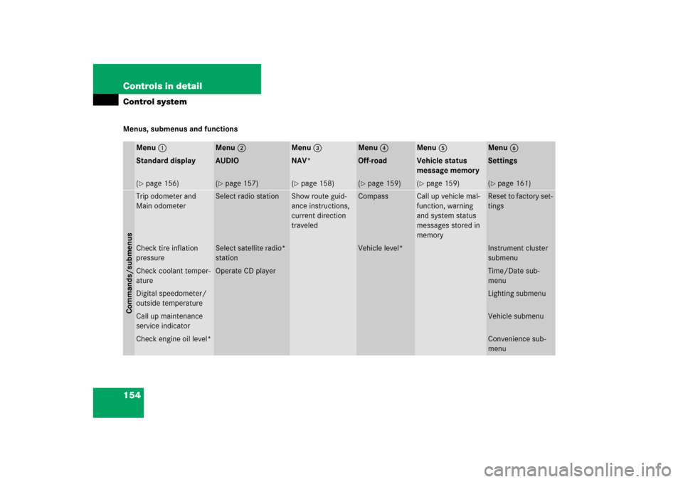
154 Controls in detailControl systemMenus, submenus and functions
Menu1
Menu2
Menu3
Menu4
Menu5
Menu6
Standard display
AUDIO
NAV*
Off-road
Vehicle status
message memory
Settings
(�page 156)
(�page 157)
(�page 158)
(�page 159)
(�page 159)
(�page 161)
Commands/submenusTrip odometer and
Main odometer
Select radio station
Show route guid-
ance instructions,
current direction
traveled
Compass
Call up vehicle mal-
function, warning
and system status
messages stored in
memory
Reset to factory set-
tings
Check tire inflation
pressure
Select satellite radio*
station
Vehicle level*
Instrument cluster
submenu
Check coolant temper-
ature
Operate CD player
Time/Date sub-
menu
Digital speedometer/
outside temperature
Lighting submenu
Call up maintenance
service indicator
Vehicle submenu
Check engine oil level*
Convenience sub-
menu
Page 163 of 539
162 Controls in detailControl systemThe submenus are arranged by hierarchy.
Scroll down with theç button, scroll up
with theæ button.
With the selection marker on the desired
submenu, use the jbutton to access
the individual functions within that sub-
menu. Once within the submenu, you can
use buttonj to move to the next func-
tion or buttonk to move to the previ-
ous function within that submenu.
The settings themselves are made with
buttonæ orç.Resetting the functions of a submenu
For each submenu you can reset all the
functions to the factory settings.
�
Move to a function in the submenu.
�
Press the reset button (
�page 24) in
the instrument cluster for approximate-
ly three seconds.
In the display you will see the request
to press the reset button again to con-
firm.
�
Press the reset button again.
All functions of the submenu will reset
to factory settings.
Page 164 of 539
163 Controls in detail
Control system
The table below shows what settings can
be changed within the various menus. De-
tailed instructions on making individual
settings can be found on the following pag-
es.INSTRUMENT CLUSTER
TIME/DATE
LIGHTING
VEHICLE
CONVENIENCE
Select speedometer display
mode
Set time (hours)
Set daytime running
lamp mode (USA only)
Adjusting compass
zone
Activate easy-entry/exit
feature*
Select language
Set time (minutes)
Set locator lighting
Calibrating compass
Set parking position for
exterior rear view mirror*
Select display (speed display
or outside temperature) for
status line
Set date (month)
Exterior lamps delayed
shut-off
Display when ignition is
switched off
Set fold-in function for
exterior rear view mir-
rors*
Set date (day)
Interior lighting delayed
shut-off
Set automatic locking
Set date (year)
Limiting opening height
of tailgate*
Page 165 of 539

164 Controls in detailControl systemInstrument cluster submenu
Access the
Instr. cluster
submenu us-
ing the jbutton via the Settings
menu. Use the
Instr. cluster
submenu
to change the instrument cluster display
settings. The following functions are avail-
able:Selecting speedometer display mode
�
Move the selection marker to the Instr. cluster
submenu using
theæ orç button.
�
Press buttonj ork repeatedly
until you see this message in the dis-
play:
Display unit
Speedometer/odometer
.
The selection marker is on the current
setting.
�
Press æ or ç to set speedome-
ter unit to
km or
miles
.
Selecting language
�
Move the selection marker to the Instr. cluster
submenu using
theæ orç button.
�
Press buttonj ork repeatedly
until you see this message in the dis-
play:
Language
.
The selection marker is on the current
setting.
�
Pressæ orç to select the lan-
guage to be used for the multifunction
display messages.
Available languages:�
German
�
English
�
French
�
Italian
�
Spanish
Function
Page
Select speedometer display
mode
164
Select language
164
Select display (speed display or
outside temperature) for status
display
165
Page 179 of 539

178 Controls in detailControl systemResetting fuel consumption statistics�
Press buttonÿ orè repeatedly
until you see the first function of the
trip computer menu.
�
Press buttonj ork repeatedly
until you see the reading that you want
to reset in the display.
�
Press and hold the reset button in the
instrument cluster (
�page 24) until
the value is reset to 0.Calling up range (distance to empty)
�
Press buttonÿ orè repeatedly
until you see the first function of the
trip computer menu.
�
Press buttonj ork repeatedly
until you see this message in the dis-
play:
Range:
In the display you will see the calculat-
ed range based on the current fuel tank
level.
TEL menu*Warning!
G
A driver’s attention to the road must always
be his/her primary focus when driving. For
your safety and the safety of others, we rec-
ommend that you pull over to a safe location
and stop before placing or taking a tele-
phone call. If you choose to use the tele-
phone while driving, please use the
hands-free device and only use the tele-
phone when weather, road and traffic condi-
tions permit.
Some jurisdictions prohibit the driver from
using a cellular telephone while driving a ve-
hicle.
Page 282 of 539

The Tele Aid system consists of three
types of response:�
automatic and manual emergency
�
r")
281 Controls in detail
Useful features
The Tele Aid system
(Tele
matic A
larm I
dentification on
D
emand)
The Tele Aid system consists of three
types of response:�
automatic and manual emergency
�
roadside assistance
�
information
The Tele Aid system is operational provid-
ing that the vehicle’s battery is charged,
properly connected, not damaged and cel-
lular and GPS coverage is available.
The speaker volume of a Tele Aid call can
be adjusted when using the volume control
on the Modular COMAND System or on the
multifunction steering wheel. To raise, turn
the rotary volume control on Modular
COMAND System clockwise or press
buttonæ on the multifunction steering
wheel. To lower, turn the rotary volume
control on Modular COMAND System con-trol counterclockwise or press
buttonç on the multifunction steering
wheel.
�
To activate, press the SOS button, the
Roadside Assistance button• or
the Information button¡, depend-
ing on the type of response required.iThe SOS button is located in the over-
head control panel.
The Roadside Assistance button•
and the Information button¡ are
located below the center armrest
cover.!The Tele Aid system utilizes the cellular
network for communication and the
GPS (G
lobal P
ositioning S
ystem) satel-
lites for vehicle location. If either of
these signals are unavailable, the
Tele Aid system may not function and if
this occurs, assistance must be sum-
moned by other means.
iWhen a Tele Aid call has been initiated,
the Modular COMAND System audio is
muted and the selected mode (radio,
CD etc.) pauses. The optional cellular
phone (if installed) inserted in cradle
switches off. If you must use this
phone, we recommend that you use it
only with the vehicle at a standstill in a
safe location. Remove the phone from
the cradle and place the call. The navi-
gation* system (if engaged) will contin-
ue to run. The display in the instrument
cluster is available for use, and spoken
commands are only available by press-
ing the RPT button on the Modular
COMAND System. A pop-up window
will appear in the Modular COMAND
System display to indicate that a Tele
Aid call is in progress. After the TeleAid
call has ended, the optional cellular
phone inserted in the cradle switches
on again. A PIN entry might be neces-
sary.
Page 352 of 539
The TPMS only functions on wheels that
are equipped with the")
351 Operation
Tires and wheels
Checking tire pressure electronically
with the Advanced Tire Pressure Moni-
toring System* (Advanced TPMS*)The TPMS only functions on wheels that
are equipped with the proper electronic
sensors. It monitors the tire inflation pres-
sure, as selected by the driver, in all four
tires. A warning is issued to alert you to a
decrease in pressure in one or more of the
tires.
Tire pressure inquiries are made using the
multifunction display.The present inflation
pressures are displayed only after a few
minutes’ travel time.
�
Switch on the ignition (
�page 34).
�
Press thej or kbutton until
the current inflation pressures for each
tire appear in the multifunction display.
iThe Advanced T
ire P
ressure M
onitoring
S
ystem* (Advanced TPMS*) is
equipped with a combination low tire
pressure/TPMS malfunction telltale in
the instrument cluster (
�page 24). De-
pending on how the telltale illuminates,
it indicates a low tire pressure condi-
tion or a malfunction in the TPMS sys-
tem itself:
�
If the telltale illuminates continu-
ously, one or more of your tires is
significantly under-inflated. There is
no malfunction in the TPMS.
�
If the telltale flashes for 60 seconds
and then stays illuminated, the
TPMS system itself is not operating
properly.
iPossible differences between the read-
ings of a tire pressure gauge of an air
hose, e.g. gas station equipment, and
the vehicle’s control system can occur.
Usually the readings issued by the con-
trol system are more precise.
iWhen the message
Tire pressure
display appears after driving sev-
eral minutes
appears in the display,
the individual inflation pressure values
are matched with the tires. The individ-
ual values are displayed after a few
minutes driving.
iWith a spare wheel without wheel sen-
sor mounted, the system may still indi-
cate the tire inflation pressure of the
removed wheel for some minutes. If
this happens, keep in mind that the in-
dicated value where the spare wheel is
mounted does not reflect the actual
spare tire inflation pressure.
Page 373 of 539

372 OperationMaintenanceClearing the maintenance service indicator
The maintenance service indicator is auto-
matically cleared after ten seconds when
you switch on the ignition or when reach-
ing the service threshold while driving. You
can also clear it yourself.�
Press reset button on the instrument
cluster (
�page 24).
Maintenance service term exceeded
If you have exceeded the suggested main-
tenance service term, you will see the fol-
lowing message in the multifunction
display:Service A exceeded by XXXXX miles (km)
Service A exceeded by XXX days
Service A exceeded by X dayIn addition, a signal sounds when the mes-
sage appears.
Any authorized Mercedes-Benz Light Truck
Center will reset the maintenance service
indicator following a completed mainte-
nance service.
Calling up the service indicator�
Switch on the ignition (
�page 34).
The standard display of the control sys-
tem appears (
�page 156).
�
Press buttonk orj on the mul-
tifunction steering wheel until the
maintenance service indicator with the
service symbol9 and the service
deadline appears in the multifunction
display.iIf the battery is disconnected, the days
of disconnection will not be included in
the count shown by the maintenance
service indicator. To arrive at the true
maintenance service deadline, you will
need to subtract these days from the
days shown in the maintenance service
indicator.
Do not confuse the maintenance ser-
vice indicator with the engine oil level
indicatorN.