Page 53 of 417
52 Getting started
Driving
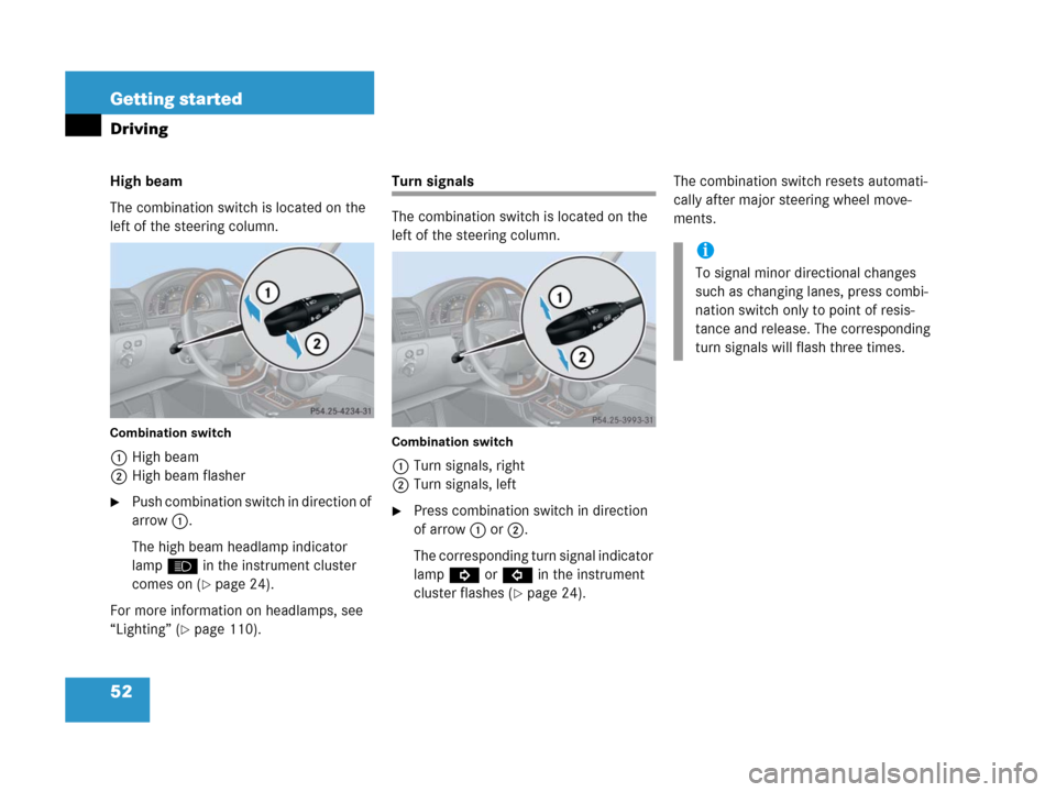
High beam
The combination switch is located on the
left of the steering column.
Combination switch
1High beam
2High beam flasher
�Push combination switch in direction of
arrow1.
The high beam headlamp indicator
lampA in the instrument cluster
comes on (
�page 24).
For more information on headlamps, see
“Lighting” (
�page 110).
Turn signals
The combination switch is located on the
left of the steering column.
Combination switch
1Turn signals, right
2Turn signals, left
�Press combination switch in direction
of arrow1 or2.
The corresponding turn signal indicator
lampK orL in the instrument
cluster flashes (
�page 24).The combination switch resets automati-
cally after major steering wheel move-
ments.
i
To signal minor directional changes
such as changing lanes, press combi-
nation switch only to point of resis-
tance and release. The corresponding
turn signals will flash three times.
Page 67 of 417

66 Safety and Security
Occupant safety
Safety guidelines for the seat belt,
emergency tensioning device and
airbag Your vehicle was originally equipped
with airbags that are designed to acti-
vate in certain impacts exceeding a
preset threshold to reduce the poten-
tial and severity of injury. It is important
to your safety and that of your passen-
ger that you replace deployed airbags
and repair any malfunctioning airbags
to make sure the vehicle will continue
to provide supplemental crash protec-
tion for occupants.
Warning!G
�Damaged seat belts or belts that were
highly stressed in an accident must be
replaced and their anchoring points
must also be checked. Use only belts in-
stalled or supplied by an authorized
Mercedes-Benz Light Truck Center.
�No modifications of any kind may be
made to any components or wiring of
the SRS. This includes changing or re-
moving any component or part of the
SRS, the installation of additional trim
material, badges, etc. over the steering
wheel hub, passenger front airbag cov-
er, outboard sides of the front seat
backrests, door trim panels, or door
frame trims, and installation of addition-
al electrical /electronic equipment on or
near SRS components and wiring. Keep
area between airbags and occupants
free from objects (e.g. packages, purs-
es, umbrellas, etc.).
�Airbags and emergency tensioning de-
vices (ETDs) are designed to function on
a one-time-only basis. An airbag or ETD
that was activated must be replaced.
�Do not pass belts over sharp edges.
They could tear.
�Do not make any modification that could
change the effectiveness of the belts.
�Do not bleach or dye seat belts as this
may severely weaken them. In a crash
they may not be able to provide ade-
quate protection.
�Never place your feet on the instrument
panel, dashboard, or on the seat. Always
keep both feet on the floor in front of the
seat.
�Airbag system components will be hot
after an airbag has inflated. Do not
touch.
Page 131 of 417

130 Controls in detail
Control system
Operate the CD player
�Turn on COMAND and select CD. Refer
to separate COMAND operating in-
structions.
�Press buttonè orÿ repeatedly
until the settings for the CD currently
being played are shown in the display.
1Current track
2Current CD (for CD changer)
�Press buttonk orj repeatedly
until the desired track is selected.
NAVI menu
The
NAVI menu contains the functions
needed to operate your navigation system.
�Press buttonè orÿ repeatedly
until you see the message
NAVI in the
display.
�If the navigation system is off, the mes-
sage
NAVI OFF is shown in the display.
�If the navigation system is on, the mes-
sage
NAVI READY is shown in the dis-
play.
Please refer to the COMAND manual for in-
structions on how to activate the route
guidance system*.
i
Additional optional satellite radio
equipment and a subscription to satel-
lite radio service provider are required
for satellite radio operation. Contact an
authorized Mercedes-Benz Light Truck
Center for details and availability for
your vehicle.
For more information, refer to separate
COMAND operating instructions.
i
Satellite radio service may be unavail-
able or interrupted from time to time
for a variety of reasons, such as envi-
ronmental or topographic conditions
and other things beyond the service
provider’s or our control. Service might
also not be available in certain places
(e.g. in tunnels, parking garages, or
within or next to buildings) or near
other technologies.
i
To select a CD from the magazine,
press a number on the COMAND sys-
tem key pad located in the center dash-
board.
Page 133 of 417

132 Controls in detail
Control system
Settings menu
In the
SETTINGS... menu there are two
functions:
�The function TO RESET: R BUTTON FOR
3SEC.
, with which you can reset all the
settings to those set at the factory.
�A collection of submenus with which
you can make individual settings for
your vehicle.
�Press buttonè orÿ repeatedly
until the
SETTINGS... menu is seen in
the display.Resetting all settings
You can reset all the functions of all sub-
menus to the factory settings.
�Press the reset button in the instru-
ment cluster (
�page 120) for approxi-
mately three seconds.
In the display you will see the request
to press the reset button again to con-
firm.
�Press the reset button again.
The functions of all the submenus will
reset to factory settings.
i
The settings you have changed will not
be reset unless you confirm the action
by pressing the reset button a second
time. Approximately five seconds after
pressing the reset button for the sec-
ond time, the
SETTINGS... menu reap-
pears in the display.
For safety reasons, the following func-
tions are not reset while driving:
�the LIGHT CIRCUIT HEADLIGHT MODE
function in the
LIGHTING submenu
�the SETTINGS KEY- DEPENDENT func-
tion in the
CONVENIENCE submenu
Page 135 of 417
134 Controls in detail
Control system
i
The settings you have changed will not
be reset unless you confirm the action
by pressing the reset button a second
time. Approximately five seconds after
pressing the reset button for the sec-
ond time, the
SETTINGS... menu reap-
pears in the display.
��
Page 136 of 417
135 Controls in detail
Control system
The table below shows what settings can
be changed within the various menus.
Detailed instructions on making individual
settings can be found on the following
pages.
INSTRUMENT CLUSTERLIGHTINGVEHICLECONVENIENCE
(�page 136)(�page 138)(�page 142)(�page 143)
Select time display modeSet daytime running lamp mode
(USA only)Set station selection mode
(radio)Activate easy-entry/exit feature
Select temperature display
modeSet locator lightingSet automatic lockingSet key-dependency
Select speedometer display
modeSet night security illuminationSet parking position for exterior
rear view mirror
Select languageSet interior lighting delayed
shut-off
Select display (speed display or
outside temperature)
Page 137 of 417

136 Controls in detail
Control system
Instrument cluster submenu
Access the
INSTRUMENT CLUSTER menu via
the
SETTINGS menu. Use the INSTRUMENT
CLUSTER
submenu to change the instru-
ment cluster display settings. The follow-
ing functions are available:Selecting time display mode
�Move the selection marker with
theæ orç button to the
INSTRUMENT CLUSTER submenu.
�Press buttonj ork repeatedly
until you see this message in the
display:
12/24 HOUR.
The selection marker is on the current
setting.
�Pressæ orç to set the 12h or
24h time display mode.Selecting temperature display mode
�Move the selection marker with
theæ orç button to the
INSTRUMENT CLUSTER submenu.
�Press buttonj ork repeatedly
until you see this message in the dis-
play:
TEMP. INDICATOR.
The selection marker is on the current
setting.
�Pressæ orç to set temperature
unit to degrees Celsius (
°C) or degrees
Fahrenheit (
°F).
FunctionPage
Select time display mode136
Select temperature display
mode136
Select speedometer display
mode137
Select language137
Select display (speed display or
outside temperature)138
Page 139 of 417

�Move the selection marker with
theæ orç button to the
INSTRUMENT CLUSTER submenu.
�Press buttonj o")
138 Controls in detail
Control system
Selecting display (speed display or out-
side temperature)
�Move the selection marker with
theæ orç button to the
INSTRUMENT CLUSTER submenu.
�Press buttonj ork repeatedly
until you see this message in the dis-
play:
SELECT DISPLAY.
The selection marker is on the current
setting.
�Pressæ orç to select the dis-
play permanently shown in the multi-
function display.Lighting submenu
Access the
LIGHTING submenu via the
SETTINGS menu. Use the LIGHTING sub-
menu to change the lamp and lighting set-
tings on your vehicle. The following
functions are available:Setting daytime running lamp mode
(USA only)
�Move the selection marker with
theæ orç button to the
LIGHTING submenu.
�Press buttonj ork repeatedly
until you see this message in the dis-
play:
LIGHT CIRCUIT HEADLIGHT MODE.
FunctionPage
Setting daytime running lamp
mode (USA only)138
Setting locator lighting139
Setting night security
illumination140
Setting interior lighting delayed
shut-off141
i
This function is not available in coun-
tries where the daytime running lamp
mode is mandatory and therefore in a
constant mode.