Page 36 of 417

35 Getting started
Unlocking
Starter switch positions
Starter switch
0For removing SmartKey
The steering is locked when the
SmartKey is removed from the starter
switch.
1Power supply for some electrical con-
sumers, such as seat adjustment2Ignition (power supply for all electrical
consumers) and driving position.
All lamps (except high beam headlamp
indicator lamp and turn signal indicator
lamps unless activated) in the instru-
ment cluster come on. If a lamp in the
instrument cluster fails to come on
when the ignition is switched on, have
it checked and replaced if necessary. If
a lamp in the instrument cluster re-
mains on after starting the engine or
comes on while driving, see “Lamps in
instrument cluster” (�page 290).
3Starting position
i
When you switch on ignition, the indi-
cator and warning lamps (except high
beam headlamp indicator lamp and
turn signal indicator lamps unless acti-
vated) in the instrument cluster come
on. The indicator and warning lamps
(except high beam headlamp indicator
lamp and turn signal indicator lamps if
activated) will go out when the engine
is running. This indicates that the re-
spective systems are operational.
i
The SmartKey can only be removed
from the starter switch with the gear
selector lever in positionP.
Page 39 of 417

38 Getting started
Adjusting
Seat adjustment
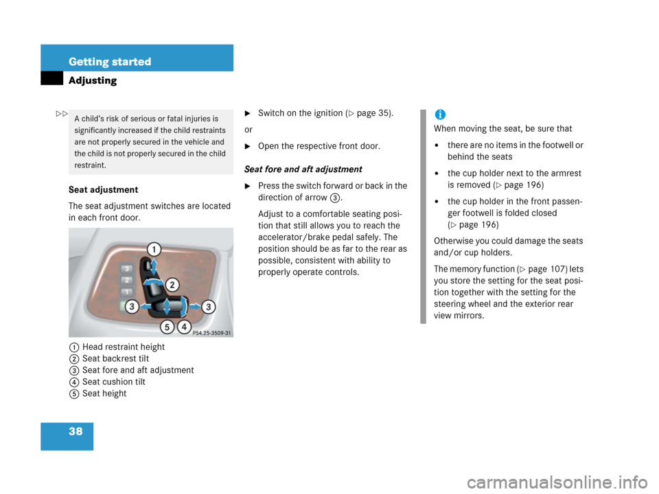
The seat adjustment switches are located
in each front door.
1Head restraint height
2Seat backrest tilt
3Seat fore and aft adjustment
4Seat cushion tilt
5Seat height
�Switch on the ignition (�page 35).
or
�Open the respective front door.
Seat fore and aft adjustment
�Press the switch forward or back in the
direction of arrow3.
Adjust to a comfortable seating posi-
tion that still allows you to reach the
accelerator/brake pedal safely. The
position should be as far to the rear as
possible, consistent with ability to
properly operate controls.
A child’s risk of serious or fatal injuries is
significantly increased if the child restraints
are not properly secured in the vehicle and
the child is not properly secured in the child
restraint.i
When moving the seat, be sure that
�there are no items in the footwell or
behind the seats
�the cup holder next to the armrest
is removed (
�page 196)
�the cup holder in the front passen-
ger footwell is folded closed
(
�page 196)
Otherwise you could damage the seats
and/or cup holders.
The memory function (
�page 107) lets
you store the setting for the seat posi-
tion together with the setting for the
steering wheel and the exterior rear
view mirrors.
��
Page 41 of 417

40 Getting started
Adjusting
Steering wheelThe lever is located on the steering column
(lower left).
1Adjusting steering column, in or out
2Adjusting steering column, up or down
�Switch on the ignition (�page 35).
or
�Open the driver’s door.Adjusting steering column in or out
�Move lever forward or back in the di-
rection of arrow1 until a comfortable
steering wheel position is reached with
your arms slightly bent at the elbow.
Adjusting steering column up or down
�Move lever up or down in the direction
of arrow2.
Make sure your legs can move freely
and that all the displays (incl. malfunc-
tion and indicator lamps) on the instru-
ment cluster are clearly visible.
For more information, see “Heated steer-
ing wheel” (
�page 215).
Warning!G
Do not adjust the steering wheel while driv-
ing. Adjusting the steering wheel while driv-
ing could cause the driver to lose control of
the vehicle.
When leaving the vehicle, always remove the
SmartKey from the starter switch, take it
with you, and lock the vehicle.
Even with the SmartKey removed from the
starter switch, the steering wheel adjust-
ment feature can be operated when the driv-
er’s door is open. Therefore, do not leave
children unattended in the vehicle, or with
access to an unlocked vehicle. Unsuper-
vised use of vehicle equipment may cause
an accident and/or serious personal injury.
i
The memory function (�page 107) lets
you store the setting for the steering
wheel together with the setting for the
seat position and the exterior rear view
mirrors.
Page 43 of 417

42 Getting started
Adjusting
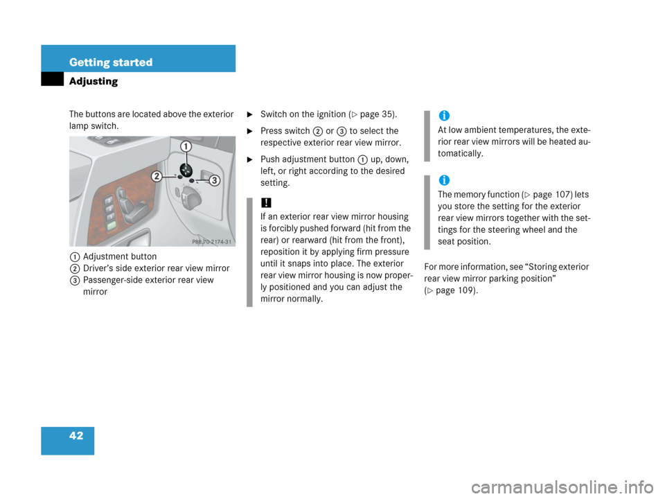
The buttons are located above the exterior
lamp switch.
1Adjustment button
2Driver’s side exterior rear view mirror
3Passenger-side exterior rear view
mirror�Switch on the ignition (�page 35).
�Press switch2 or3 to select the
respective exterior rear view mirror.
�Push adjustment button1 up, down,
left, or right according to the desired
setting.
For more information, see “Storing exterior
rear view mirror parking position”
(
�page 109).
!
If an exterior rear view mirror housing
is forcibly pushed forward (hit from the
rear) or rearward (hit from the front),
reposition it by applying firm pressure
until it snaps into place. The exterior
rear view mirror housing is now proper-
ly positioned and you can adjust the
mirror normally.
i
At low ambient temperatures, the exte-
rior rear view mirrors will be heated au-
tomatically.
i
The memory function (�page 107) lets
you store the setting for the exterior
rear view mirrors together with the set-
tings for the steering wheel and the
seat position.
Page 54 of 417
53 Getting started
Driving
Windshield wipers
The combination switch is located on the
left of the steering column.
Combination switch
1Single wipe
Wiping with windshield washer fluid
2Switching on windshield wipers
�Switch on the ignition (�page 35).Switching on windshield wipers
�Turn the combination switch to the de-
sired position depending on the inten-
sity of the rain.
0Windshield wipers off
IIntermittent wiping
IINormal wiper speed
IIIFast wiper speed
i
Intermittent wiping interval is depen-
dent on wetness of windshield. Pauses
between wipes are automatically con-
trolled by the rain sensor.
!
Do not operate the wipers when the
windshield is dry. Dust that accumu-
lates on a windshield might scratch the
glass and/or damage the wiper blades
when wiping occurs on a dry wind-
shield. If it is necessary to operate the
wipers in dry weather conditions, al-
ways operate the wipers with wind-
shield washer fluid (
�page 54).
Page 56 of 417

55 Getting started
Driving
�Switch on the ignition (�page 35).
Interval wiping
Switching on
�Press upper half1 of the switch.
Indicator lamp2 comes on.
Switching off
�Press upper half1 of the switch
again.
Indicator lamp2 goes out.Wiping with windshield washer fluid
�Press and hold lower half3 of the
switch.
The wiper operates with washer fluid.
The rear window will be wiped for ap-
proximately another five seconds after
the switch is released.
For information on filling up the washer
reservoir, see “Windshield/rear window
washer system and headlamp cleaning
system” (
�page 249).
Problems while driving
The engine runs erratically and misfires
�An ignition cable may be damaged.
�The engine electronics may not be op-
erating properly.
�Unburned gasoline may have entered
the catalytic converter and damaged it.
�Give very little gas.
�Have the problem repaired by an au-
thorized Mercedes-Benz Light Truck
Center as soon as possible.
i
The rear window wiper will also auto-
matically engage if
�the windshield wipers are engaged.
�the gear selector lever is placed
inR “Reverse”.
Page 84 of 417

83 Safety and Security
Driving and safety systems
4-ETS
The 4-ETS improves vehicle’s ability to uti-
lize available traction, especially under
slippery road conditions. The brakes are
applied to the spinning wheel and power is
allowed to flow to the wheel(s) with trac-
tion.
The 4-ETS function is available between ve-
hicle speeds of 0 mph (km/h) and 37 mph
(60 km/h).
The ESP warning lampv in the instru-
ment cluster (
�page 24) comes on when
you switch on ignition (
�page 35). It goes
out when the engine is running.
The ESP warning lampv starts to flash
at any vehicle speed, as soon as the tires
lose traction and the wheels begin to spin.For more information, see “Practical hints”
(
�page 295).
Warning!G
When you see the ESP warning lampv
flashing in the instrument cluster, then pro-
ceed as follows:
�While driving off, apply as little throttle
as possible.
�While driving ease up on the accelera-
tor.
�Adapt your speed and driving style to
the prevailing road conditions.
Failure to observe these guidelines could
cause the vehicle to skid.
The 4-ETS cannot prevent accidents result-
ing from excessive speed.
!
The engine must be shut off when
�the parking brake is being tested on
a brake test dynamometer.
�the vehicle is being towed with one
axle raised.
Otherwise, the 4-ETS will engage the
brakes and seriously damage the brake
system.
Page 85 of 417

84 Safety and Security
Driving and safety systems
EBB
The EBB enhances braking effectiveness
by allowing the rear brakes to supply a
greater proportion of the braking effort in
straight line braking circumstances with-
out a loss of vehicle stability.ESP
The Electronic Stability Program (ESP)
monitors the vehicle’s traction (force of ad-
hesive friction between the tires and the
road surface) and handling.
The ESP recognizes when a wheel is spin-
ning or if the vehicle starts to skid. By ap-
plying brakes to the appropriate wheel and
by limiting engine output, the ESP works to
stabilize the vehicle.
The ESP warning lampv in the instru-
ment cluster (
�page 24) flashes when the
ESP is engaged.
The ESP warning lampv comes on
when you switch on ignition (
�page 35). It
goes out when the engine is running.
Warning!G
Never switch off the ESP when you see the
ESP warning lamp v flashing in the in-
strument cluster. In this case proceed as fol-
lows:
�While driving off, apply as little throttle
as possible.
�While driving ease up on the accelera-
tor.
�Adapt your speed and driving style to
the prevailing road conditions.
Failure to observe these guidelines could
cause the vehicle to skid.
The ESP cannot prevent accidents resulting
from excessive speed.