Page 442 of 514

441 Practical hints
Replacing bulbs
Front turn signal lamp bulb�
Turn bulb socket3 counterclockwise
and remove it.
�
Press gently onto the bulb and turn
counterclockwise out of bulb
socket3.
�
Press the new bulb gently into bulb
socket3 and turn clockwise until it
engages.
�
Place bulb socket3 back into the
lamp and turn it clockwise.
Parking and standing lamp bulb
�
Turn housing cover2 counterclock-
wise and remove it.
�
Pull out bulb socket6 with the bulb.
�
Pull the bulb out of the bulb socket6.
�
Press the new bulb into bulb socket6.
�
Press bulb socket6 back into the
lamp.
�
Align housing cover2 and turn it
clockwise.Front lamps Bi-Xenon*-type
1Bulb socket for turn signal lamp
2Housing cover for high beam flasher,
parking and standing lamp
3Housing cover for Bi-Xenon* headlamp4Bulb holder for high beam flasher bulb
5Bulb socket for parking and standing
lamp bulb
Warning!
G
Do not remove the cover
3
for the Bi-Xe-
non* headlamp. Because of high voltage in
xenon lamps, it is dangerous to replace the
bulb or repair the lamp and its components.
We recommend that you have such work
done by a qualified technician.
Page 445 of 514

444 Practical hintsReplacing wiper bladesRemoving and installing wiper blades
�
Remove SmartKey from starter switch
(vehicles with KEYLESS-GO*: make
sure the vehicle's on board electronics
have status 0).
Removing wiper blades
1Unlocking
2Tab
�
Pull the tab2 in the direction of
arrow1.
The wiper blade is unlocked.
�
Lift up the wiper arm as far as you need
to remove the wiper blade.
�
Carefully fold the wiper arm back to
rest on the windshield.
Warning!
G
For safety reasons, switch off wipers and
remove SmartKey from starter switch
(vehicles with KEYLESS-GO*: make sure the
vehicle’s on-board electronics have
status
0) before replacing a wiper blade.
Otherwise, the wiper motor could suddenly
turn on and cause injury.
!Never open the hood when the wiper
arms are folded forward.
For your convenience, we recommend
that you have this work carried out by
an authorized Mercedes-Benz Center.
!Hold on to the wiper arm when folding
the wiper arm back. If released, the
force of the impact from the tensioning
spring could crack the windshield.
Page 447 of 514
.")
446 Practical hintsFlat tire
Preparing the vehicle�
Park the vehicle in a safe distance from
moving traffic on a hard, flat surface
when possible.
�
Turn on the hazard warning flashers
(�page 133).
�
Turn the steering wheel so that the
front wheels are in a straight ahead
position.
�
Set the parking brake (
�page 57).
�
Move the gear selector lever toP.
Vehicles with SmartKey:
�
Turn off the engine (
�page 58).
�
Remove the SmartKey from the starter
switch.Vehicles with SmartKey with
KEYLESS-GO*:
�
Turn off the engine by pressing the
KEYLESS-GO* start/stop button on the
gear selector lever once (
�page 59).
�
Open the driver’s door (this puts the ig-
nition in position0 (
�page 36), same
as with the SmartKey removed from
the starter switch). The driver’s door
then can be closed again.
�
Have any passenger exit the vehicle at
a safe distance from the roadway.
Warning!
G
The dimensions of the Minispare wheel are
different from those of the road wheels. As
a result, the vehicle handling characteristics
change when driving with a Minispare wheel
mounted. Adapt your driving style
accordingly.
The spare wheel is for temporary use only.
When driving with spare wheel mounted,
ensure proper tire inflation pressure and do
not exceed a vehicle speed of 50 mph
(80 km/h).
Drive to the nearest Mercedes-Benz Center
as soon as possible to have the spare wheel
replaced with a regular road wheel.
Never operate the vehicle with more than
one Minispare wheel mounted.
Do not switch off the ESP
® when a Minis-
pare wheel is mounted.
iOpen door only when conditions are
safe to do so.
Page 448 of 514
.
�
Take the wheel wrench and the jack
out of the trunk (
�page 416).")
447 Practical hints
Flat tire
Mounting the Minispare wheel
Preparing the vehicle
Prepare the vehicle as described on
(�page 446).
�
Take the wheel wrench and the jack
out of the trunk (
�page 416).
�
Take the Minispare wheel and wheel
bolts out of the trunk (
�page 416).Lifting the vehicle
�
Prevent the vehicle from rolling away
by blocking wheels with wheel chocks
or other sizeable objects.
One wheel chock is included with the
vehicle tool kit (
�page 413).
When changing wheel on a level surface:
�
Place the wheel chock in front of and
another sizeable object behind the
wheel that is diagonally opposite to the
wheel being changed.
Always try lifting the vehicle using the jack
on a level surface. However, should cir-
cumstances require you to do so on a hill,
place the wheel chock and the other size-
able object as follows:
�
Place the wheel chock and another
sizeable object on the downhill side
blocking both wheels of the axle not
being worked on.
Warning!
G
The jack is designed exclusively for jacking
up the vehicle at the jack take-up brackets
built into both sides of the vehicle. To help
avoid personal injury, use the jack only to lift
the vehicle during a wheel change. Never
get beneath the vehicle while it is supported
by the jack. Keep hands and feet away from
the area under the lifted vehicle. Always
firmly set parking brake and block wheels
before raising vehicle with jack.
Do not disengage parking brake while the
vehicle is raised. Be certain that the jack is
always vertical (plumb line) when in use,
especially on hills. Always try to use the jack
on a level surface. Make sure the jack arm is
fully seated in the jack take-up bracket.
Always lower the vehicle onto sufficient
capacity jackstands before working under
the vehicle.
Page 449 of 514
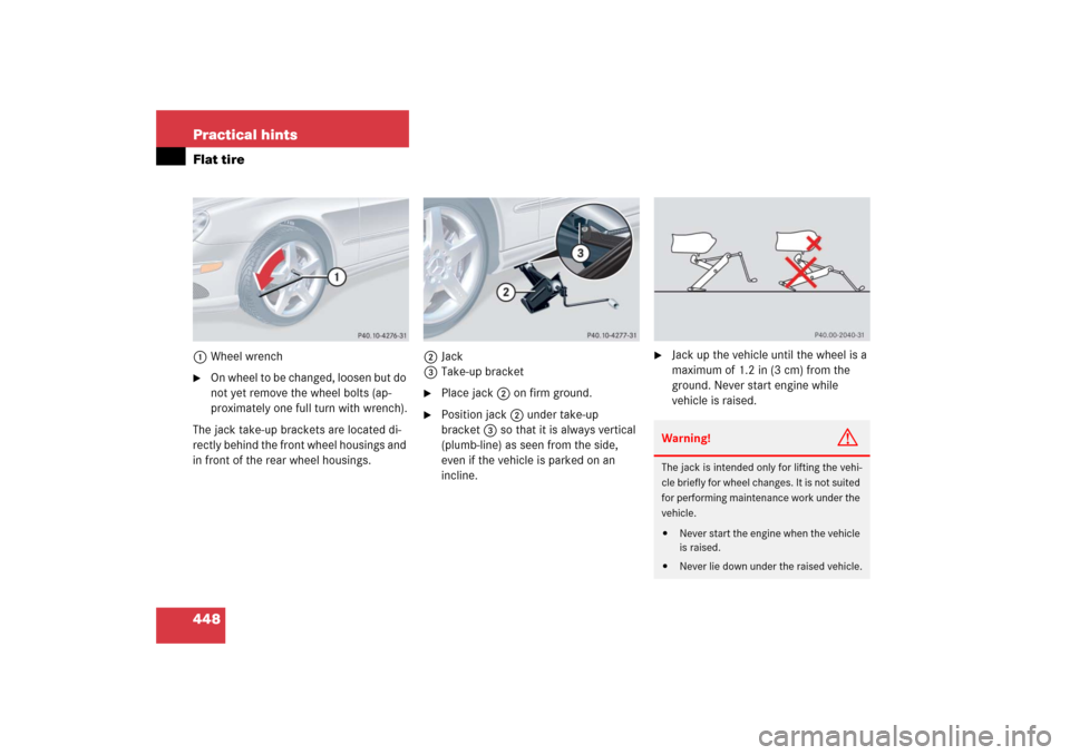
448 Practical hintsFlat tire1Wheel wrench�
On wheel to be changed, loosen but do
not yet remove the wheel bolts (ap-
proximately one full turn with wrench).
The jack take-up brackets are located di-
rectly behind the front wheel housings and
in front of the rear wheel housings.2Jack
3Take-up bracket
�
Place jack 2 on firm ground.
�
Position jack2 under take-up
bracket3 so that it is always vertical
(plumb-line) as seen from the side,
even if the vehicle is parked on an
incline.
�
Jack up the vehicle until the wheel is a
maximum of 1.2 in (3 cm) from the
ground. Never start engine while
vehicle is raised.Warning!
G
The jack is intended only for lifting the vehi-
cle briefly for wheel changes. It is not suited
for performing maintenance work under the
vehicle.�
Never start the engine when the vehicle
is raised.
�
Never lie down under the raised vehicle.
Page 451 of 514
450 Practical hintsFlat tire
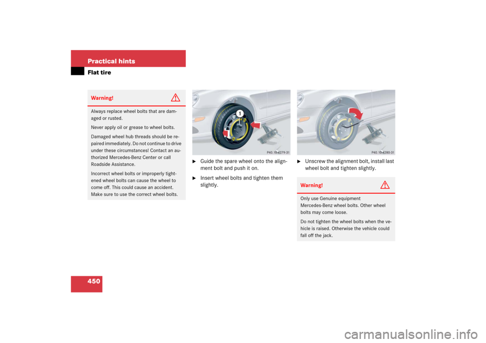
�
Guide the spare wheel onto the align-
ment bolt and push it on.
�
Insert wheel bolts and tighten them
slightly.
�
Unscrew the alignment bolt, install last
wheel bolt and tighten slightly.
Warning!
G
Always replace wheel bolts that are dam-
aged or rusted.
Never apply oil or grease to wheel bolts.
Damaged wheel hub threads should be re-
paired immediately. Do not continue to drive
under these circumstances! Contact an au-
thorized Mercedes-Benz Center or call
Roadside Assistance.
Incorrect wheel bolts or improperly tight-
ened wheel bolts can cause the wheel to
come off. This could cause an accident.
Make sure to use the correct wheel bolts.
Warning!
G
Only use Genuine equipment
Mercedes-Benz wheel bolts. Other wheel
bolts may come loose.
Do not tighten the wheel bolts when the ve-
hicle is raised. Otherwise the vehicle could
fall off the jack.
Page 452 of 514
451 Practical hints
Flat tire
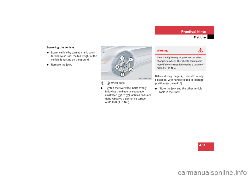
Lowering the vehicle�
Lower vehicle by turning crank coun-
terclockwise until the full weight of the
vehicle is resting on the ground.
�
Remove the jack.
1 - 5 Wheel bolts
�
Tighten the five wheel bolts evenly,
following the diagonal sequence
illustrated (1 to 5), until all bolts are
tight. Observe a tightening torque
of 80 lb-ft (110 Nm).Before storing the jack, it should be fully
collapsed, with handle folded in (storage
position) (
�page 415).
�
Store the jack and the other vehicle
tools in the trunk.Warning!
G
Have the tightening torque checked after
changing a wheel. The wheels could come
loose if they are not tightened to a torque of
80 lb-ft (110 Nm).
Page 453 of 514

452 Practical hintsFlat tireMOExtended system*
The MOExtended system allows you to
continue driving your vehicle even if there
is a total loss of pressure in one or more
tires.
You may only use the MOExtended system
in conjunction with the Run Flat Indicator*.
!The maximum distance in emergency
mode depends on the vehicle’s load. It
is 30 miles (50 km) if the vehicle is par-
tially loaded and 18 miles (30 km) if the
vehicle is fully loaded.
The point at which the maximum driv-
ing distance begins in emergency
mode is when the warning message
appears in the multifunction display
indicating that there is a loss of tire
inflation pressure.
Do not exceed the maximum speed of
50 mph (80 km/h).
Warning!
G
In emergency mode, your vehicle’s driving
characteristics are diminished in such situa-
tions as:�
driving around curves
�
while braking
�
while accelerating rapidly
Therefore, your driving style must be adapt-
ed accordingly. Avoid abrupt steering and
driving maneuvers, as well as driving over
obstacles (road curbs, potholes, or off-road
areas). This is especially important if the ve-
hicle is heavily loaded.
The emergency driving distance that can be
achieved greatly depends on the demands
placed on the vehicle. Depending on speed,
load, driving maneuvers, road conditions,
outside temperature, etc., the distance can
be significantly shorter or, if the vehicle is
driven cautiously, somewhat longer.
Do not continue driving in emergency mode
if�
you notice knocking sounds
�
the vehicle starts to shake
�
smoke develops and you smell rubber
�
ESP
® is intervening continuously
�
you notice tears on the tire sidewalls
After driving in emergency mode, you must
have the rims inspected by an authorized
Mercedes-Benz Center to check if they are
suitable for further use. The failed tire must
be replaced in any case.iWhen replacing individual or all tires on
the vehicle, make sure only matching
tires marked with “MOExtended” are
mounted in the size specified for your
vehicle (
�page 471).