Page 132 of 514
131 Controls in detail
Lighting
Rear fog lamp (driver’s side only)�
Switch on the front fog lamps
(�page 130).
�
Pull out the exterior lamp switch to
second stop.
The rear fog lamp is switched on.
The yellow indicator lamp† in the
exterior lamp switch comes on
(�page 127).
�
Push in the exterior lamp switch to first
stop.
The rear fog lamp switches off.
The yellow indicator lamp† in the
exterior lamp switch goes out.
The front fog lamps remain lit.
Combination switch
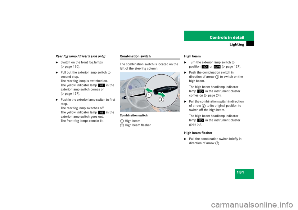
The combination switch is located on the
left of the steering column.Combination switch1High beam
2High beam flasherHigh beam
�
Turn the exterior lamp switch to
positionB orU (
�page 127).
�
Push the combination switch in
direction of arrow1 to switch on the
high beam.
The high beam headlamp indicator
lampA in the instrument cluster
comes on (
�page 24).
�
Pull the combination switch in direction
of arrow2 to its original position to
switch off the high beam.
The high beam headlamp indicator
lampA in the instrument cluster
goes out.
High beam flasher
�
Pull the combination switch briefly in
direction of arrow2.
Page 157 of 514
156 Controls in detailControl systemLighting submenu
Access the
Lighting
submenu via the
Set-
tings
menu. Use the
Lighting
submenu
to change the lamp and lighting settings on
your vehicle.
The following functions are available:Setting daytime running lamp mode
(USA only)
�
Move the selection marker with
buttonæ orç to the
Lighting
submenu.
�
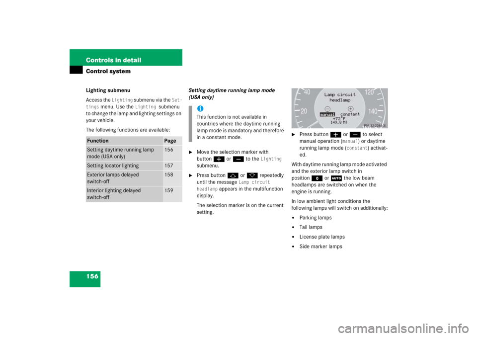
Press buttonj ork repeatedly
until the message
Lamp circuit
headlamp
appears in the multifunction
display.
The selection marker is on the current
setting.
�
Press buttonæ orç to select
manual operation (
manual
) or daytime
running lamp mode (
constant
) activat-
ed.
With daytime running lamp mode activated
and the exterior lamp switch in
positionM or U the low beam
headlamps are switched on when the
engine is running.
In low ambient light conditions the
following lamps will switch on additionally:
�
Parking lamps
�
Tail lamps
�
License plate lamps
�
Side marker lamps
Function
Page
Setting daytime running lamp
mode (USA only)
156
Setting locator lighting
157
Exterior lamps delayed
switch-off
158
Interior lighting delayed
switch-off
159
iThis function is not available in
countries where the daytime running
lamp mode is mandatory and therefore
in a constant mode.
Page 385 of 514
384 Practical hintsWhat to do if …?
On the pages that follow, you will find a
compilation of the most important warning
and malfunction messages that may
appear in the display.
For your convenience the messages are
divided into two sections:�
Text messages (
�page 385)
�
Symbol messages (
�page 395)
iSwitching on the ignition causes all
instrument cluster lamps (except low
beam headlamp indicator lamp, high
beam headlamp indicator lamp, and
turn signal indicator lamps unless
activated) as well as the multifunction
display to come on. Make sure the
lamps and the multifunction display are
in working order before starting your
journey.
Page 407 of 514
406 Practical hintsWhat to do if …?Display symbol
Display message
Possible cause/consequence
Possible solution
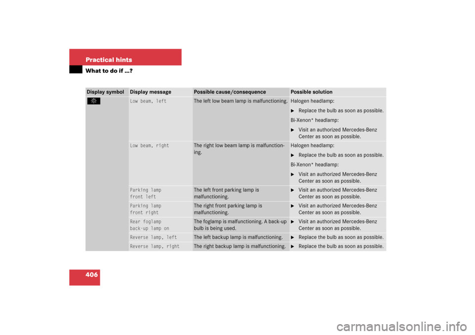
.
Low beam, left
The left low beam lamp is malfunctioning.
Halogen headlamp:�
Replace the bulb as soon as possible.
Bi-Xenon* headlamp:
�
Visit an authorized Mercedes-Benz
Center as soon as possible.
Low beam, right
The right low beam lamp is malfunction-
ing.
Halogen headlamp:�
Replace the bulb as soon as possible.
Bi-Xenon* headlamp:
�
Visit an authorized Mercedes-Benz
Center as soon as possible.
Parking lamp
front left
The left front parking lamp is
malfunctioning.
�
Visit an authorized Mercedes-Benz
Center as soon as possible.
Parking lamp
front right
The right front parking lamp is
malfunctioning.
�
Visit an authorized Mercedes-Benz
Center as soon as possible.
Rear foglamp
back-up lamp on
The foglamp is malfunctioning. A back-up
bulb is being used.
�
Visit an authorized Mercedes-Benz
Center as soon as possible.
Reverse lamp, left
The left backup lamp is malfunctioning.
�
Replace the bulb as soon as possible.
Reverse lamp, right
The right backup lamp is malfunctioning.
�
Replace the bulb as soon as possible.
Page 439 of 514
438 Practical hintsReplacing bulbsSafe vehicle operation depends on proper
exterior lighting and signaling. It is there-
fore essential that all bulbs and lamp
assemblies are in good working order at all
times.
Correct headlamp adjustment is extremely
important. Have headlamps checked and
readjusted at regular intervals and when a
bulb has been replaced. See an authorized
Mercedes-Benz Center for headlamp
adjustment.
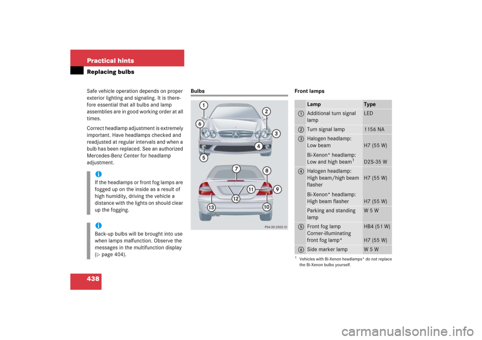
Bulbs Front lamps
iIf the headlamps or front fog lamps are
fogged up on the inside as a result of
high humidity, driving the vehicle a
distance with the lights on should clear
up the fogging.iBack-up bulbs will be brought into use
when lamps malfunction. Observe the
messages in the multifunction display
(�page 404).
Lamp
Type
1
Additional turn signal
lamp
LED
2
Turn signal lamp
1156 NA
3
Halogen headlamp:
Low beam
Bi-Xenon* headlamp:
Low and high beam
1
1Vehicles with Bi-Xenon headlamps* do not replace
the Bi-Xenon bulbs yourself.
H7 (55 W)
D2S-35 W
4
Halogen headlamp:
High beam/high beam
flasher
Bi-Xenon* headlamp:
High beam flasher
H7 (55 W)
H7 (55 W)
Parking and standing
lamp
W 5 W
5
Front fog lamp
Corner-illuminating
front fog lamp*
HB4 (51 W)
H7 (55 W)
6
Side marker lamp
W 5 W
Page 441 of 514
440 Practical hintsReplacing bulbsReplacing bulbs for front lamps
Before you start to replace a bulb for a
front lamp, do the following first:�
Turn the exterior lamp switch to
positionM (
�page 127).
�
Open the hood (
�page 321).
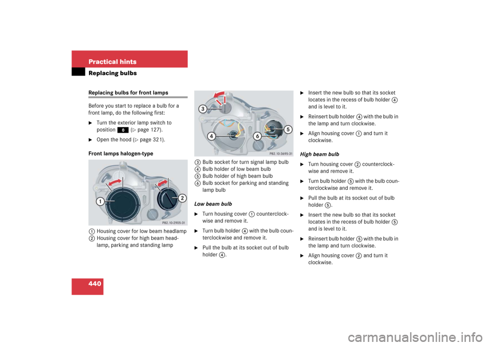
Front lamps halogen-type
1Housing cover for low beam headlamp
2Housing cover for high beam head-
lamp, parking and standing lamp3Bulb socket for turn signal lamp bulb
4Bulb holder of low beam bulb
5Bulb holder of high beam bulb
6Bulb socket for parking and standing
lamp bulb
Low beam bulb
�
Turn housing cover1 counterclock-
wise and remove it.
�
Turn bulb holder4 with the bulb coun-
terclockwise and remove it.
�
Pull the bulb at its socket out of bulb
holder4.
�
Insert the new bulb so that its socket
locates in the recess of bulb holder4
and is level to it.
�
Reinsert bulb holder4 with the bulb in
the lamp and turn clockwise.
�
Align housing cover1 and turn it
clockwise.
High beam bulb
�
Turn housing cover2 counterclock-
wise and remove it.
�
Turn bulb holder5 with the bulb coun-
terclockwise and remove it.
�
Pull the bulb at its socket out of bulb
holder5.
�
Insert the new bulb so that its socket
locates in the recess of bulb holder5
and is level to it.
�
Reinsert bulb holder5 with the bulb in
the lamp and turn clockwise.
�
Align housing cover2 and turn it
clockwise.
Page 488 of 514
487 Technical terms
ABS
(A
ntilock B
rake S
ystem)
Prevents the wheels from locking up
during braking so that the vehicle can
continue to be steered.
Accessory weight
(
�page 355)
Air pressure
(�page 355)
Alignment bolt
Metal pin with thread. The centering
pin is an aid used when changing a tire
to align the wheel with the wheel hub.
Aspect ratio
(�page 355)
Bar
(�page 355)
BAS
(Brake A
ssist S
ystem)
System for potentially reducing braking
distances in emergency braking situa-
tions. The system is activated when it
senses an emergency based on how
fast the brake is applied.Bead
(
�page 355)
Bi-Xenon headlamps*
Headlamps which use an electric arc as
the light source and produce a more in-
tense light than filament headlamps.
Bi-Xenon headlamps produce low
beam and high beam.
CAC
(Customer A
ssistance C
enter)
Mercedes-Benz customer service cen-
ter, which can help you with any ques-
tions about your vehicle and provide
assistance in the event of a break-
down.
CAN system
(C
ontroller A
rea N
etwork)
Data bus network serving to control ve-
hicle functions such as door locking or
windshield wiping.Cockpit
All instruments, switches, buttons and
indicator/warning lamps in the passen-
ger compartment needed for vehicle
operation and monitoring.
Cold tire inflation pressure
(
�page 355)
COMAND
(Cockpit M
anagement and D
ata Sys-
tem)
Information and operating center for
vehicle sound and communications
systems, including the radio and the
navigation system, as well as other op-
tional equipment (CD changer*, tele-
phone, etc.).
Control system
The control system is used to call up
vehicle information and to change
component settings. Information and
messages appear in the multifunction
display. The driver uses the buttons on
the multifunction steering wheel to
navigate through the system and to ad-
just settings.
Page 500 of 514

499 Index
Fuel consumption statistics
After start 161
Resetting 162
Since last reset 162
Fuel filler flap 318
Locking/unlocking 318
Opening in an emergency 421
Fuel reserve warning lamp 25
Fuel tank
Capacity 480
Filler flap 318
Message in display 403
Fuel, Premium
unleaded gasoline 319, 482
Fuels, coolants, lubricants etc.
Capacities 479
Fuses 462
Aids for changing fuses 462
Fuse box (main)
in passenger compartment 463
Fuse box in engine compartment 463
Fuse box in trunk 464
Fuse chart 462
Fuse extractor 462
Replacing 462
Spare fuses 462G
Garage door opener 29, 296
Gasoline see Fuel
GAWR 355
Gear range 171, 488
Automatic transmission 171
Limiting 171
Shifting into optimal 173
Gear selector lever 28, 48, 166
Cleaning 371
Lock 49
Message in display 393
One-touch gearshifting 173
Position 166, 168
Position indicator 25, 140, 167
Unlocking in an emergency 422
Global locking/unlocking see
Key, SmartKey or KEYLESS-GO* 98
Global Positioning System see GPS
Glove box 23, 278
Gloves 413
Good visibility 181
GPS 488
Gross Axle Weight Rating see GAWR
Gross Vehicle Weight Rating see GVWR
Gross Vehicle Weight see GVWGVW 355
GVWR 356
H
Halogen headlamp see Headlamps
Hands-free microphone 29
Hard plastic trim items, cleaning 371
Hazard warning flasher 133
Head restraints 38, 119
Active head restraints 73
Front seat 119
Power seat, Adjusting 38
Rear seat 119
Rear seat, Lowering 120
Rear seat, Raising 120
Headlamp
cleaning system* 181, 329, 486
Headlamp delayed shut-off see
Delayed shut-off, Exterior lamps
Headlamps
Automatic headlamp mode 128
Bi-Xenon* 441, 487
Cleaning lenses 369
Daytime running lamp mode 129
Halogen 440
High beam see High beam flasher
High beam see High beam headlamps