Page 220 of 378

Black plate (220,1)
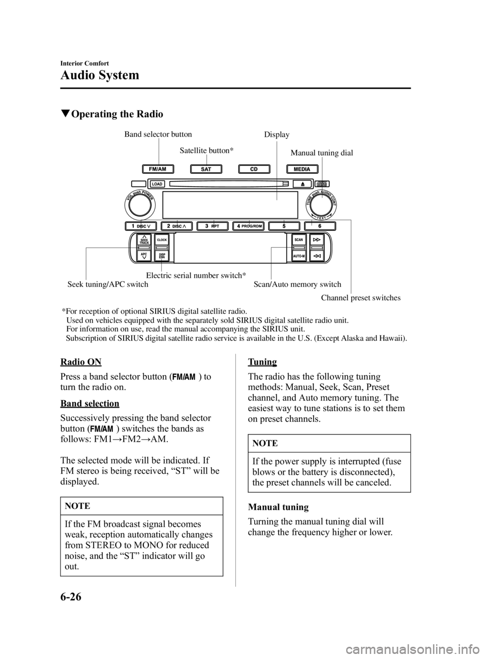
qOperating the Radio
Band selector buttonDisplay
Manual tuning dial
Channel preset switches
Satellite button*
Electric serial number switch* Scan/Auto memory switch
Seek tuning/APC switch
*For reception of optional SIRIUS digital satellite radio.
Used on vehicles equipped with the separately sold SIRIUS digital satellite radio\
unit.For information on use, read the manual accompanying the SIRIUS unit.
Subscri
ption of SIRIUS digital satellite radio service is available in the U.S. (Except Alaska and Hawaii).
Radio ON
Press a band selector button (
)to
turn the radio on.
Band selection
Successively pressing the band selector
button (
) switches the bands as
follows: FM1 →FM2 →AM.
The selected mode will be indicated. If
FM stereo is being received, “ST ”will be
displayed.
NOTE
If the FM broadcast signal becomes
weak, reception automatically changes
from STEREO to MONO for reduced
noise, and the “ST ”indicator will go
out.
Tuning
The radio has the following tuning
methods: Manual, Seek, Scan, Preset
channel, and Auto memory tuning. The
easiest way to tune stations is to set them
on preset channels.
NOTE
If the power supply is interrupted (fuse
blows or the battery is disconnected),
the preset channels will be canceled.
Manual tuning
Turning the manual tuning dial will
change the frequency higher or lower.
6-26
Interior Comfort
Audio System
MX-5_8U35-EA-05F_Edition4 Page220
Thursday, October 6 2005 11:4 AM
Form No.8U35-EA-05F
Page 224 of 378

Black plate (224,1)
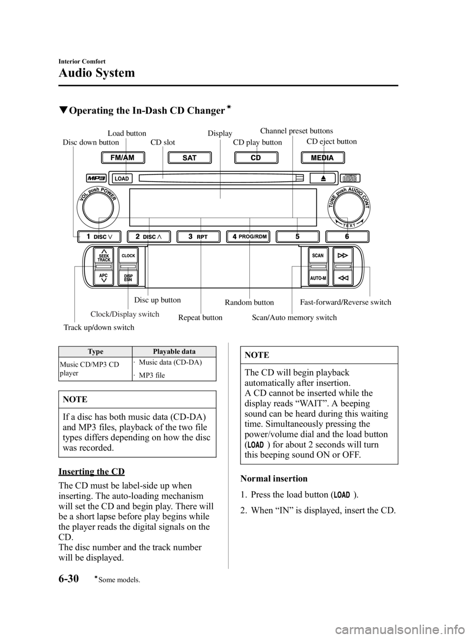
qOperating the In-Dash CD Changerí
Load button
CD play button
CD slot
Fast-forward/Reverse switchDisc down buttonDisplay
Track up/down switchRepeat button Scan/Auto memory switchRandom button
Disc up button
CD eject button
Channel preset buttons
Clock/Display switch
Type
Playable data
Music CD/MP3 CD
player · Music data (CD-DA)
· MP3 file
NOTE
If a disc has both music data (CD-DA)
and MP3 files, playback of the two file
types differs depending on how the disc
was recorded.
Inserting the CD
The CD must be label-side up when
inserting. The auto-loading mechanism
will set the CD and begin play. There will
be a short lapse before play begins while
the player reads the digital signals on the
CD.
The disc number and the track number
will be displayed.
NOTE
The CD will begin playback
automatically after insertion.
A CD cannot be inserted while the
display reads
“WAIT ”. A beeping
sound can be heard during this waiting
time. Simultaneously pressing the
power/volume dial and the load button
(
) for about 2 seconds will turn
this beeping sound ON or OFF.
Normal insertion
1. Press the load button (
).
2. When “IN ”is displayed, insert the CD.
6-30
Interior Comfort
íSome models.
Audio System
MX-5_8U35-EA-05F_Edition4 Page224
Thursday, October 6 2005 11:4 AM
Form No.8U35-EA-05F
Page 240 of 378
Black plate (240,1)
Parking in an Emergency
The hazard warning lights should always
be used when you stop on or near a
roadway.
The hazard warning lights warn other
drivers that your vehicle is a traffic hazard
and that they must take extreme caution
when near it.
Depress the hazard warning flasher and all
six turn signals will flash.
NOTE
lThe turn signals don't work when the
hazard warning lights are on.
lCheck local regulations about the use
of hazard warning lights while the
vehicle is being towed. They may
forbid it.
7-2
In Case of an Emergency
Parking in an Emergency
MX-5_8U35-EA-05F_Edition4 Page240
Thursday, October 6 2005 11:4 AM
Form No.8U35-EA-05F
Page 252 of 378

Black plate (252,1)
NOTE
lMake sure the jack is well lubricated
before using it.
(With Tire Pressure Monitoring
System)
lBe sure to register the tire pressure
sensor ID signal code whenever tires
or wheels are changed (page 5-30).
1. Park on a level surface off the right-of- way and firmly set the parking brake.
2. Put a vehicle with an automatic transmission in Park (P), a manual
transmission in Reverse (R) or 1, and
turn off the engine.
3. Turn on the hazard warning flasher.
4. Have everyone get out of the vehicle and away from the vehicle and traffic.
5. Remove the jack, and tool (page 7-5).
6. Block the wheel diagonally opposite the tire to be changed. When blocking
a wheel, place a tire block both in front
and behind the tire.
NOTE
When blocking a tire, use rocks or
wood blocks of sufficient size to hold
the tire in place.
qRemoving a Tire
1. Loosen the lug nuts by turning them
counterclockwise one turn each, but
don't remove any until the tire has been
raised off the ground.
2. Place the jack under the jackingposition closest to the tire being
changed.
Jacking position
7-14
In Case of an Emergency
Flat Tire
MX-5_8U35-EA-05F_Edition4 Page252
Thursday, October 6 2005 11:5 AM
Form No.8U35-EA-05F
Page 303 of 378
Black plate (303,1)
Light Bulbs
High-mount brake light
License plate lights
Trunk light Reverse lights
Rear turn signal lights
Brake lights / Taillights
Side-marker lights
Overhead light
Head lights (High beam)
Parking light
Fog lights
Headlights (Low beam)
Front turn signal lights
Side-marker lights Some models.
Maintenance and Care
Owner Maintenance
8-35
MX-5_8U35-EA-05F_Edition4 Page303
Thursday, October 6 2005 11:6 AM
Form No.8U35-EA-05F
Page 307 of 378

Black plate (307,1)
3. Turn the center section of the plasticretainers counterclockwise and remove
them, then remove the mudguard.
Removal
Installation
4. Turn the socket and bulb assembly counterclockwise, and carefully pull it
backward.
5. Disconnect the socket and bulb assembly from the electrical connector
by pressing the tab on the connector
with your finger and pulling it.
6. Install the new socket and bulbassembly in the reverse order of
removal.
NOTE
lIf the halogen bulb is accidentally
touched, it should be cleaned with
rubbing alcohol before being used.
lUse the protective cover and carton
of the replacement bulb to dispose of
the old bulb promptly out of the
reach of children.
Front turn signal lights
1. If you are changing the right front turn
signal light bulb, start the engine, turn
the steering wheel all the way to the
left, and turn off the engine. If you are
changing the left front turn signal light
bulb, turn the steering wheel to the
right.
2. Turn the screws counterclockwise and remove them.
Maintenance and Care
Owner Maintenance
8-39
MX-5_8U35-EA-05F_Edition4 Page307
Thursday, October 6 2005 11:6 AM
Form No.8U35-EA-05F
Page 309 of 378
Black plate (309,1)
3. Disconnect the bulb from the socket.
4. Install the new bulb in the reverse orderof removal.
Brake lights/Taillights, Rear turn signal
lights, Reverse lights
1. Pull the center section of the plasticretainers and remove them, then
remove the trunk end trim.
Removal
Installation
2. On the side the bulb is to be replaced, pull the center section of the plastic
retainers and remove them, then
remove the trunk side trim.
Removal
Installation
3. Turn the socket and bulb assembly counterclockwise and remove it.
4. Disconnect the bulb from the socket.
Brake lights/Taillights Rear turn signal lights
Reverse lights
5. Install the new bulb in the reverse order of removal.
Maintenance and Care
Owner Maintenance
8-41
MX-5_8U35-EA-05F_Edition4 Page309
Thursday, October 6 2005 11:6 AM
Form No.8U35-EA-05F
Page 314 of 378
Black plate (314,1)
DESCRIPTIONFUSE
RATING PROTECTED COMPONENT
17 BTN 30 A For protection of various circuits
18 MAIN 120 A For protection of all circuits
19 EGI INJ 10 A Injector
20 EGI COMP1 10 A Engine control system
21 EGI COMP2 10 A Engine control system
22 HEAD LOW L 15 A Headlight low beam (LH)
23 HEAD LOW R 15 A Headlight low beam (RH)
24 HEAD 15 A Headlight high beams
25 P.WIND 20 A Power windows
26 ENGINE 15 A Engine control system
27 WIPER 20 A Windshield wipers and washer
28 DRL 15 A DRL
í, Headlight levellingí
29HORN 15 A Horn
30 STOP 10 A Brake lights
31 ETV 10 A Electric throttle valve
32 FUEL PUMP 15 A Fuel Pump
33 HAZARD 10 A Turn signals, Hazard warning flashers
34 P.WIND2 20 A ―
35 IG KEY1 40 A For protection of various circuits
8-46
Maintenance and Care
íSome models.
Owner Maintenance
MX-5_8U35-EA-05F_Edition4 Page314
Thursday, October 6 2005 11:6 AM
Form No.8U35-EA-05F