Page 179 of 322
457
1
2
3
4
5
6
7
8
910
Driving your vehicle
2. Press the left temperature controlto adjust the driver side tempera-
ture. Press the right temperature
control to adjust the passenger
side temperature. Adjusting the driver and passenger
side temperature equally
1. Press the DUAL button again to
deactivate DUAL mode (the indi-
cator light in the button is off). The
passenger side temperature will
be set to the same as the driver
side temperature.
2. Press the left temperature control button. The driver and passenger
side temperature will be adjusted
equally.
Temperature conversionIf the battery has been discharged or
disconnected, the temperature mode
will reset as Centigrade degrees.
This is normal condition and you can
switch the temperature mode
between Centigrade to Fahrenheit as
follows;
While depressing the MODE button,
depress the DUAL button for 3 sec-
onds or more. The display will
change from Centigrade to
Fahrenheit, or from Fahrenheit to
Centigrade.
Page 201 of 322

59
Driving tips
Driving too fast through large pud-dles can affect your brakes. If you
must go through puddles, try to
drive through them slowly.
If you believe you may have gotten your brakes wet, apply them lightly
while driving until normal braking
operation returns.
Winter driving We recommend that you carryemergency equipment, including
tire chains, a window scraper,
windshield de-icer, a bag of sand
or salt, flares, a small shovel and
jumper cables.
Make sure you have sufficient eth- ylene-glycol coolant in the radiator.
Check the battery condition and cables. Cold temperatures reduce
the capacity of any battery, so it
must be in excellent condition to
provide enough winter starting
power.
Make sure the engine oil viscosity is suitable for cold weather.
Check the ignition system for loose connections and damage. Use antifreeze-formulated wind-
shield washer fluid. (Do not use
engine coolant antifreeze.)
Do not use the parking brake if it might freeze. When parking, shift
to P (Park) with an automatic
transaxle and block the rear
wheels.
1
2
3
4
5
6
7
8
910
Page 216 of 322

Driving tips24
5
1
2
3
4
5
6
7
8
910
ProgrammingYour vehicle may require the ignition
switch to be turned to the ACC posi-
tion for programming and/or opera-
tion of HomeLink. It is also recom-
mended that a new battery be
replaced in the hand-held transmitter
of the device being programmed to
HomeLink for quicker training and
accurate transmission of the radio-
frequency.
Follow these steps to train your
HomeLink mirror: 1. When programming the buttons
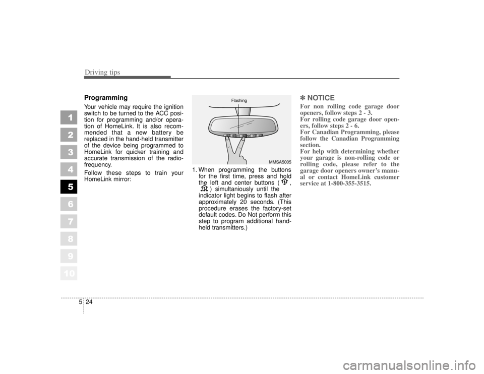
for the first time, press and hold
the left and center buttons ( , ) simultaniously until the
indicator light begins to flash after
approximately 20 seconds. (This
procedure erases the factory-set
default codes. Do Not perform this
step to program additional hand-
held transmitters.)
✽ ✽ NOTICEFor non rolling code garage door
openers, follow steps 2 - 3.
For rolling code garage door open-
ers, follow steps 2 - 6.
For Canadian Programming, please
follow the Canadian Programming
section.
For help with determining whether
your garage is non-rolling code or
rolling code, please refer to the
garage door openers owner’s manu-
al or contact HomeLink customer
service at 1-800-355-3515.
MMSA5005
Flashing
Page 224 of 322

In case of an emergency46EMERGENCY STARTING Jump starting Jump starting can be dangerous if
done incorrectly. Therefore, to avoid
harm to yourself or damage to your
vehicle or battery, follow the jump
starting procedures listed on page
6-6. If in doubt, we strongly recom-
mend that you have a competent
technician or towing service jump
start your vehicle.
✽ ✽NOTICEUse only a 12-volt jumper system.
You can damage a 12-volt starting
motor, ignition system, and other
electrical parts beyond repair by use
of a 24-volt power supply (either two
12-volt batteries in series or a 24-
volt motor generator set).
1
2
3
4
5
6
7
8
910
WARNING
- Battery
• Keep all flames or sparks away from the battery. The bat-
tery produces hydrogen gas
which may explode if exposed
to flame or sparks.
Do not attempt to jump start the vehicle if the discharged
battery is frozen or if the elec-
trolyte level is low; the battery
may rupture or explode.
WARNING
- Battery
Never attempt to check the elec-
trolyte level of the battery as
this may cause the battery to
rupture or explode causing seri-
ous injury.
Page 225 of 322
65
In case of an emergency
Connecting jumper cables
1
2
3
4
5
6
7
8
910
1GHA401
Connect cables in numerical order
and disconnect in reverse order.
Discharged batteryJumper Cables
Booster battery
Page 226 of 322

In case of an emergency66Jump starting procedure 1. Make sure the booster battery is12-volt and that its negative termi-
nal is grounded.
2. If the booster battery is in another vehicle, do not allow the vehicles
to touch.
3. Turn off all unnecessary electrical loads.
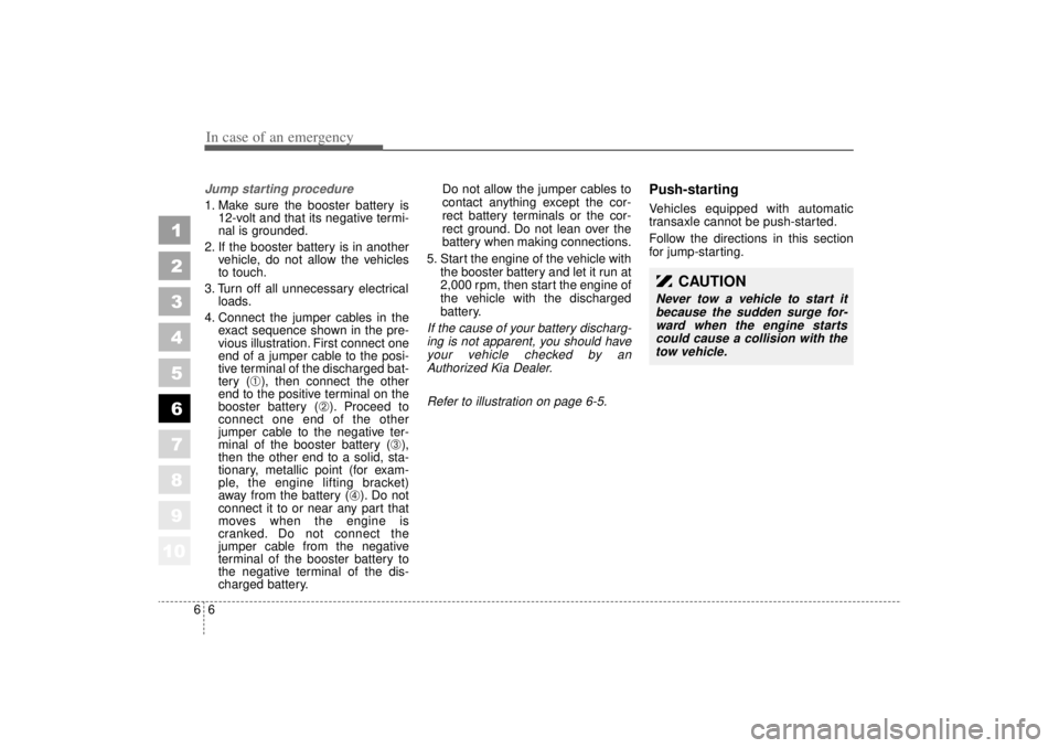
4. Connect the jumper cables in the exact sequence shown in the pre-
vious illustration. First connect one
end of a jumper cable to the posi-
tive terminal of the discharged bat-
tery (
➀), then connect the other
end to the positive terminal on the
booster battery (
➁). Proceed to
connect one end of the other
jumper cable to the negative ter-
minal of the booster battery (
➂),
then the other end to a solid, sta-
tionary, metallic point (for exam-
ple, the engine lifting bracket)
away from the battery (
➃). Do not
connect it to or near any part that
moves when the engine is
cranked. Do not connect the
jumper cable from the negative
terminal of the booster battery to
the negative terminal of the dis-
charged battery. Do not allow the jumper cables to
contact anything except the cor-
rect battery terminals or the cor-
rect ground. Do not lean over the
battery when making connections.
5. Start the engine of the vehicle with the booster battery and let it run at
2,000 rpm, then start the engine of
the vehicle with the discharged
battery.
If the cause of your battery discharg-ing is not apparent, you should haveyour vehicle checked by anAuthorized Kia Dealer.
Refer to illustration on page 6-5.
Push-starting Vehicles equipped with automatic
transaxle cannot be push-started.
Follow the directions in this section
for jump-starting.
1
2
3
4
5
6
7
8
910
CAUTION
Never tow a vehicle to start itbecause the sudden surge for-ward when the engine startscould cause a collision with thetow vehicle.
Page 227 of 322
67
In case of an emergency
ELECTRICAL CIRCUIT PROTECTION Fuses A vehicle’s electrical system is pro-
tected from electrical overload dam-
age by fuses.
This vehicle has two fuse panels,
one located in the driver's side knee
bolster, the other in the engine com-
partment near the battery.If any of your vehicle’s lights, acces-
sories, or controls do not work, check
the appropriate circuit fuse. If a fuse
has blown, the element inside the
fuse will be melted.
If the electrical system does not
work, first check the driver’s side
fuse panel.
Always replace a blown fuse with
one of the same rating.
If the replacement fuse blows, this
indicates an electrical problem. Avoid
using the system involved and imme-
diately consult an Authorized Kia
Dealer.
Two kinds of fuses are used: stan-
dard for lower amperage rating andmain for higher amperage ratings.
1
2
3
4
5
6
7
8
910
MMSA6003
Standard
Main fuse
Normal Normal Blown
Blown
Page 229 of 322
69
In case of an emergency
To check the fuse or relay in the
engine compartment, remove the
engine compartment shroud.1. Turn the ignition switch and all
other switches off.
2. Remove the fuse box cover by removing the bolt on the cover and
unhooking the tab on one end and
tilting the cover back toward the
other end.
3. Check the fuses. If one is blown, replace it with a new one of the
same rating.
✽ ✽NOTICEAfter checking the fuse box in the
engine compartment, securely
install the fuse box cover. If not,
electrical failures may occur from
water leaking in.
Main fuseIf the BATT (60A) or ALT (140A) fuse
are blown, it must be removed as fol-
lows:
1. Disconnect the negative battery
cable.
2. Remove the screws shown in the picture above.
3. Replace the fuse with a new one of the same rating.
4. Reinstall in the reverse order of removal.
1
2
3
4
5
6
7
8
910
1GHA404
1GHA411
1GHA405
Engine compartment
➀
➁
➂➀
Junction Box
➁ Main Fuse
➂ Relay Box