Page 240 of 322
In case of an emergency20
6
1
2
3
4
5
6
7
8
910
IF YOU HAVE A FLAT TIRE The spare tire, jack, jack handle,
wheel lug nut wrench and spanner
are stored in the trunk compartment.
Move the carpeting out of the way to
reach this equipment.
The jack assembly is located in the
trunk, under the carpeting, in the
right-hand corner.
Removing the spare tire Turn the tire hold-down wing bolt
counterclockwise.
Store the tire in the reverse order of
removal.
To prevent the spare tire and tools
from “rattling” while the vehicle is in
motion, store them properly.
Changing tires Jacking instructions The jack is provided for emergency
tire changing only.
Follow jacking instructions to reduce
the possibility of personal injury.
1GHA406
1GHA407
Page 243 of 322

623
In case of an emergency
1
2
3
4
5
6
7
8
910
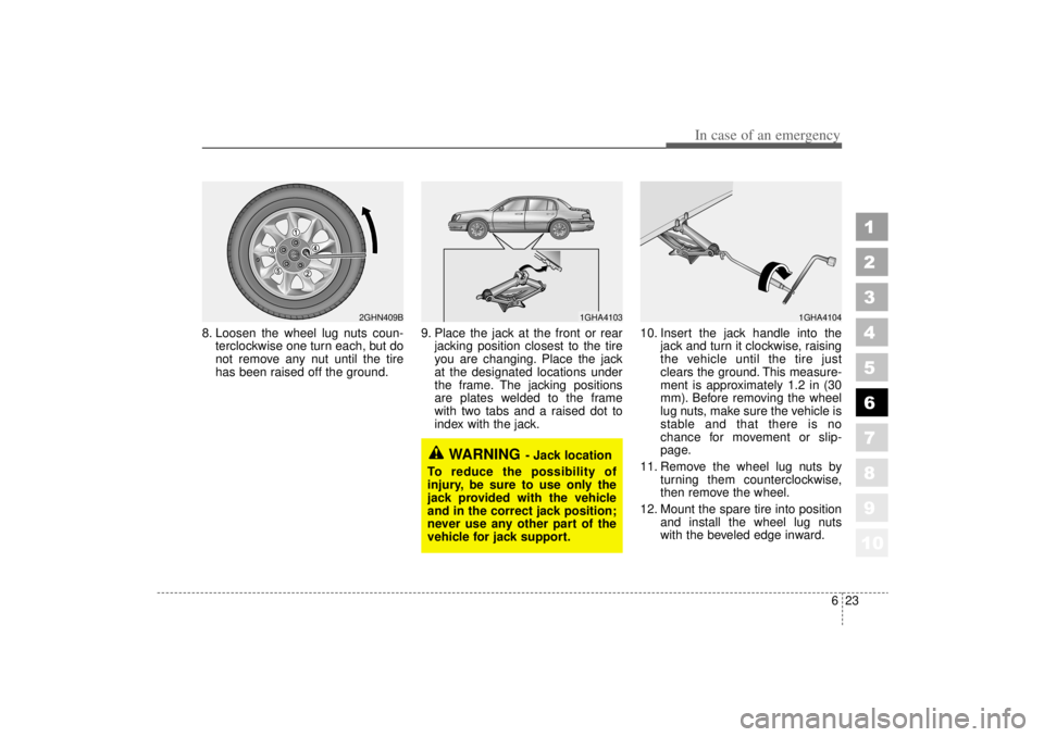
8. Loosen the wheel lug nuts coun-terclockwise one turn each, but do
not remove any nut until the tire
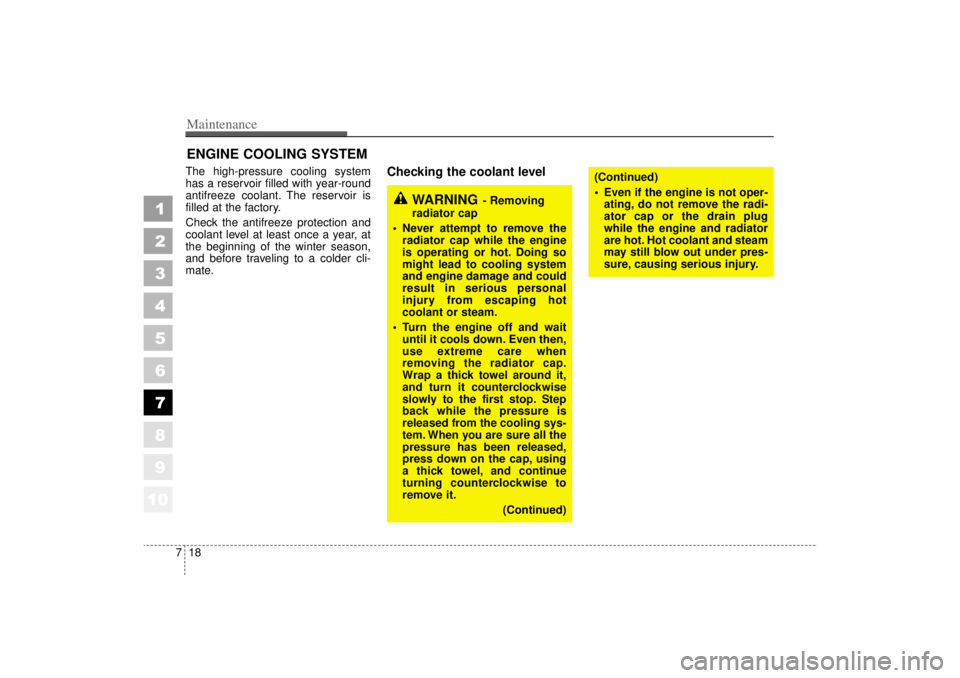
has been raised off the ground. 9. Place the jack at the front or rear
jacking position closest to the tire
you are changing. Place the jack
at the designated locations under
the frame. The jacking positions
are plates welded to the frame
with two tabs and a raised dot to
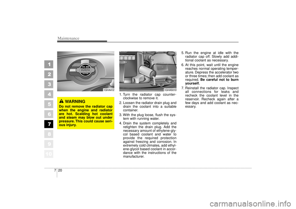
index with the jack. 10. Insert the jack handle into the
jack and turn it clockwise, raising
the vehicle until the tire just
clears the ground. This measure-
ment is approximately 1.2 in (30
mm). Before removing the wheel
lug nuts, make sure the vehicle is
stable and that there is no
chance for movement or slip-
page.
11. Remove the wheel lug nuts by turning them counterclockwise,
then remove the wheel.
12. Mount the spare tire into position and install the wheel lug nuts
with the beveled edge inward.
WARNING
- Jack location
To reduce the possibility of
injury, be sure to use only the
jack provided with the vehicle
and in the correct jack position;
never use any other part of the
vehicle for jack support.
1GHA4104
1GHA4103
2GHN409B
Page 262 of 322

Maintenance18
7
1
2
3
4
5
6
7
8
910
ENGINE COOLING SYSTEM The high-pressure cooling system
has a reservoir filled with year-round
antifreeze coolant. The reservoir is
filled at the factory.
Check the antifreeze protection and
coolant level at least once a year, at
the beginning of the winter season,
and before traveling to a colder cli-
mate.
Checking the coolant level
WARNING
- Removing
radiator cap
Never attempt to remove the radiator cap while the engine
is operating or hot. Doing so
might lead to cooling system
and engine damage and could
result in serious personal
injury from escaping hot
coolant or steam.
Turn the engine off and wait until it cools down. Even then,
use extreme care when
removing the radiator cap.
Wrap a thick towel around it,
and turn it counterclockwise
slowly to the first stop. Step
back while the pressure is
released from the cooling sys-
tem. When you are sure all the
pressure has been released,
press down on the cap, using
a thick towel, and continue
turning counterclockwise to
remove it.
(Continued)
(Continued)
Even if the engine is not oper-ating, do not remove the radi-
ator cap or the drain plug
while the engine and radiator
are hot. Hot coolant and steam
may still blow out under pres-
sure, causing serious injury.
Page 264 of 322

Maintenance20
7
1
2
3
4
5
6
7
8
910
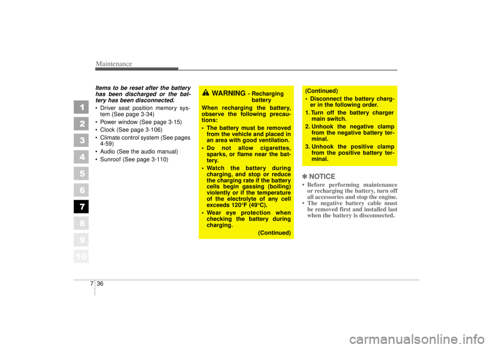
1. Turn the radiator cap counter-
clockwise to remove it.
2. Loosen the radiator drain plug and drain the coolant into a suitable
container.
3. With the plug loose, flush the sys- tem with running water.
4. Drain the system completely and retighten the drain plug. Add the
necessary amount of ethylene-gly-
col based coolant and water to
provide the required protection
against freezing and corrosion. In
extremely cold climates, add ethyl-
ene-glycol based coolant in accor-
dance with the instructions of the
manufacturer. 5. Run the engine at idle with the
radiator cap off. Slowly add addi-
tional coolant as necessary.
6. At this point, wait until the engine reaches normal operating temper-
ature. Depress the accelerator two
or three times; then add coolant as
required. Be careful not to burn
yourself.
7. Reinstall the radiator cap. Inspect all connections for leaks and
recheck the coolant level in the
reservoir. Recheck again after a
few days and add coolant as nec-
essary.
1GHA5010
1GHA412
WARNING
Do not remove the radiator cap
when the engine and radiator
are hot. Scalding hot coolant
and steam may blow out under
pressure. This could cause seri-
ous injury.
Page 280 of 322

Maintenance36
7
1
2
3
4
5
6
7
8
910
Items to be reset after the battery
has been discharged or the bat-tery has been disconnected. Driver seat position memory sys-
tem (See page 3-34)
Power window (See page 3-15)
Clock (See page 3-106)
Climate control system (See pages
4-59)
Audio (See the audio manual)
Sunroof (See page 3-110)
✽ ✽
NOTICE• Before performing maintenance
or recharging the battery, turn off
all accessories and stop the engine.
• The negative battery cable must be removed first and installed last
when the battery is disconnected.
WARNING
- Recharging
battery
When recharging the battery,
observe the following precau-
tions:
The battery must be removed
from the vehicle and placed in
an area with good ventilation.
Do not allow cigarettes,
sparks, or flame near the bat-
tery.
Watch the battery during
charging, and stop or reduce
the charging rate if the battery
cells begin gassing (boiling)
violently or if the temperature
of the electrolyte of any cell
exceeds 120°F (49°C).
Wear eye protection when
checking the battery during
charging.
(Continued)
(Continued)
Disconnect the battery charg-
er in the following order.
1. Turn off the battery charger main switch.
2. Unhook the negative clamp from the negative battery ter-
minal.
3. Unhook the positive clamp from the positive battery ter-
minal.
Page 289 of 322
745
Maintenance
1
2
3
4
5
6
7
8
910
1. Open the hood.
2. Remove the engine compartmentshroud.
3. Remove the headlight bulb cover by turning it counterclockwise.
4. Disconnect the headlight bulb socket-connector.
5. Unsnap the headlight bulb retain- ing wire by depressing the end
and pushing it upward.
6. Remove the bulb from the head- light assembly.
WARNING
- Halogen
bulbs
Halogen bulbs contain pres-
surized gas that will produce
flying pieces of glass if bro-
ken.
Always handle them carefully,
and avoid scratches and abra-
sions. If the bulbs are lit, avoid
contact with liquids. Never
touch the glass with bare
hands. Residual oil may cause
the bulb to overheat and burst
when lit. A bulb should be
operated only when installed
in a headlight.
(Continued)
(Continued)
If a bulb becomes damaged or
cracked, replace it immediate-
ly and carefully dispose of it.
Wear eye protection when
changing a bulb. Allow the
bulb to cool down before han-
dling it.
1GHA423
2GHA744
Page 290 of 322
Maintenance46
7
1
2
3
4
5
6
7
8
910
7. Install a new headlight bulb and
snap the headlight bulb retaining
wire into position by aligning the
wire with the groove on the bulb.
8. Connect the headlight bulb socket- connector.
9. Install the headlight bulb cover by turning it clockwise.
Headlight (HID type), position
and front fog light, turn signal
light and side mark light bulb
replacementIf the light bulb is not operating, have
the vehicle checked by an authorized
Kia Dealer.
* HID : High Intensity Discharge
WARNING
- HID Headlight
low beam (if equipped)
Do not attempt to replace or
inspect the low beam (XENON
bulb) due to electric shock dan-
ger. If the low beam (XENON
bulb) is not working, have your
vehicle checked by an
Authorized Kia Dealer.
Page 293 of 322
749
Maintenance
1
2
3
4
5
6
7
8
910
2. Remove the service cover by turn-ing the plastic screw counterclock-
wise and removing the cover. 3. Remove the socket from the
assembly by turning the socket
counterclockwise until the tabs on
the socket align with the slots on
the assembly. 4. Remove the bulb from the socket
by pressing it in and rotating it until
the tabs on the bulb align with the
slots in the socket. Pull the bulb
out of the socket.
5. Insert a new bulb by inserting it into the socket and rotating it until
it locks into place.
6. Install the socket in the assembly by aligning the tabs on the socket
with the slots in the assembly.
Push the socket into the assembly
and turn the socket clockwise.
7. Replace the service cover and tighten the screw.
1GHA430
1GHA429
1GHA501