Page 2014 of 3383

WHEEL HUBFAX-5
CE F
G H
I
J
K L
M A
B
FA X
Revision: November 2009 2006 QX56
WHEEL HUBPFP:43202
On-Vehicle Inspection and ServiceEDS003BN
Make sure the mounting conditions (looseness, backlash) of each component and component status (wear,
damage) are normal.
WHEEL BEARING INSPECTION
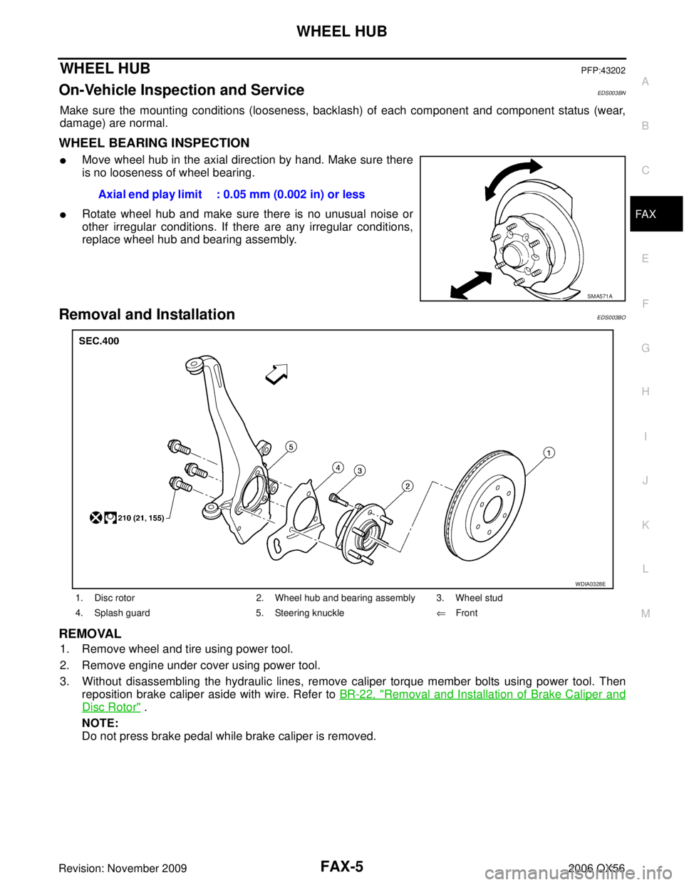
�Move wheel hub in the axial direction by hand. Make sure there
is no looseness of wheel bearing.
�Rotate wheel hub and make sure there is no unusual noise or
other irregular conditions. If there are any irregular conditions,
replace wheel hub and bearing assembly.
Removal and InstallationEDS003BO
REMOVAL
1. Remove wheel and tire using power tool.
2. Remove engine under cover using power tool.
3. Without disassembling the hydraulic lines, remove caliper torque member bolts using power tool. Then
reposition brake caliper aside with wire. Refer to BR-22, "
Removal and Installation of Brake Caliper and
Disc Rotor" .
NOTE:
Do not press brake pedal while brake caliper is removed. Axial end play limit : 0.05 mm (0.002 in) or less
SMA571A
1. Disc rotor
2. Wheel hub and bearing assembly 3. Wheel stud
4. Splash guard 5. Steering knuckle⇐Front
WDIA0328E
Page 2022 of 3383
SERVICE DATA AND SPECIFICATIONS (SDS)FAX-13
CE F
G H
I
J
K L
M A
B
FA X
Revision: November 2009 2006 QX56
SERVICE DATA AND SPECIFICATIONS (SDS)PFP:00030
Wheel BearingEDS003BR
Drive ShaftEDS003BS
Boot BandsEDS004G1
Unit: mm (in)
Wheel bearing axial end play
0.05 mm (0.002 in) or less
Drive shaft joint typeFinal drive side Rzeppa
Wheel side Rzeppa
Grease Quality
Nissan Genuine Grease or
equivalent
Capacity Final drive side
130 - 150 g (4.58 - 5.29 oz)
Wheel side 145 - 165 g (5.11 - 5.82 oz)
Boot length Final drive side "L "
145 mm (5.71 in)
Wheel side "L " 168.4 mm (6.63 in)
WDIA0055E
Dimension "M" 1.0 - 4.0 (0.039 - 0.157)
DSF0047D
Page 2023 of 3383
FAX-14
SERVICE DATA AND SPECIFICATIONS (SDS)
Revision: November 20092006 QX56
Page 2024 of 3383

FFD-1
FRONT FINAL DRIVE
D DRIVELINE/AXLE
CONTENTS
CE F
G H
I
J
K L
M
SECTION
A
B
FFD
Revision: November 2009 2006 QX56
PRECAUTIONS .....................................................
..... 2
Precautions for Servicing Front Final Drive ......... ..... 2
PREPARATION ...................................................... ..... 3
Special Service Tools .......................................... ..... 3
Commercial Service Tools ................................... ..... 5
NOISE, VIBRATION AND HARSHNESS (NVH)
TROUBLESHOOTING ........................................... ..... 6
NVH Troubleshooting Chart ................................ ..... 6
DIFFERENTIAL GEAR OIL ................................... ..... 7
Changing Differential Gear Oil ............................ ..... 7
DRAINING ........................................................ ..... 7
FILLING ............................................................ ..... 7
Checking Differential Gear Oil ............................. ..... 7
DIFFERENTIAL GEAR OIL LEAKAGE AND
LEVEL .............................................................. ..... 7
FRONT OIL SEAL ................................................. ..... 8
Removal and Installation ..................................... ..... 8
REMOVAL ........................................................ ..... 8
INSTALLATION ................................................ ..... 9
SIDE OIL SEAL ..................................................... ... 10
Removal and Installation ..................................... ... 10
REMOVAL ........................................................ ... 10
INSTALLATION ................................................ ... 10CARRIER COVER .................................................
... 11
Removal and Installation ..................................... ... 11
REMOVAL ........................................................ ... 11
INSTALLATION ................................................ ... 11
FRONT FINAL DRIVE ASSEMBLY ....................... ... 12
Removal and Installation ..................................... ... 12
REMOVAL ........................................................ ... 12
INSTALLATION ................................................ ... 13
Disassembly and Assembly ................................. ... 14
COMPONENTS ................................................ ... 14
ASSEMBLY INSPECTION AND ADJUSTMENT ... 15
DISASSEMBLY ................................................ ... 18
INSPECTION AFTER DISASSEMBLY ............. ... 23
ADJUSTING AND SELECTING WASHERS .... ... 23
ASSEMBLY ...................................................... ... 25
SERVICE DATA AND SPECIFICATIONS (SDS) ... ... 31
General Specifications ......................................... ... 31
Inspection and Adjustment .................................. ... 31
DRIVE GEAR RUNOUT ................................... ... 31
SIDE GEAR CLEARANCE ............................... ... 31
PRELOAD TORQUE ........................................... 31
BACKLASH ...................................................... ... 31
COMPANION FLANGE RUNOUT .................... ... 31
SELECTIVE PARTS ......................................... ... 32
Page 2026 of 3383

PREPARATIONFFD-3
CE F
G H
I
J
K L
M A
B
FFD
Revision: November 2009 2006 QX56
PREPARATIONPFP:00002
Special Service ToolsEDS0044Y
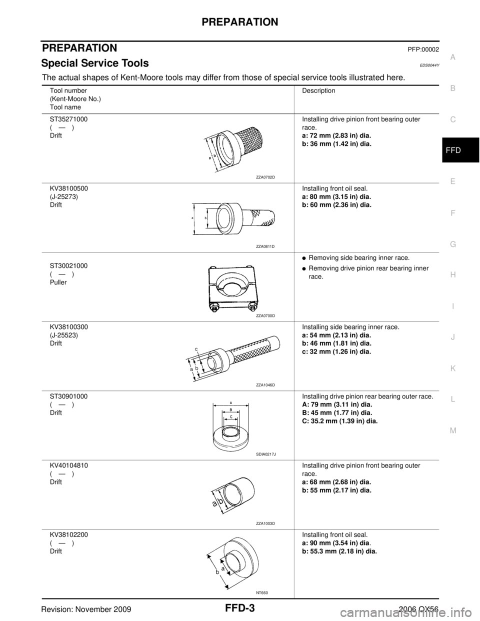
The actual shapes of Kent-Moore tools may differ from those of special service tools illustrated here.
Tool number
(Kent-Moore No.)
Tool nameDescription
ST35271000
(—)
Drift Installing drive pinion front bearing outer
race.
a: 72 mm (2.83 in) dia.
b: 36 mm (1.42 in) dia.
KV38100500
(J-25273)
Drift Installing front oil seal.
a: 80 mm (3.15 in) dia.
b: 60 mm (2.36 in) dia.
ST30021000
(—)
Puller
�Removing side bearing inner race.
�Removing drive pinion rear bearing inner
race.
KV38100300
(J-25523)
Drift Installing side bearing inner race.
a: 54 mm (2.13 in) dia.
b: 46 mm (1.81 in) dia.
c: 32 mm (1.26 in) dia.
ST30901000
(—)
Drift Installing drive pinion rear bearing outer race.
A: 79 mm (3.11 in) dia.
B: 45 mm (1.77 in) dia.
C: 35.2 mm (1.39 in) dia.
KV40104810
(—)
Drift Installing drive pinion front bearing outer
race.
a: 68 mm (2.68 in) dia.
b: 55 mm (2.17 in) dia.
KV38102200
(—)
Drift Installing front oil seal.
a: 90 mm (3.54 in) dia
.
b: 55.3 mm (2.18 in) dia.
ZZA0702D
ZZA0811D
ZZA0700D
ZZA1046D
SDIA0217J
ZZA1003D
NT660
Page 2028 of 3383
PREPARATIONFFD-5
CE F
G H
I
J
K L
M A
B
FFD
Revision: November 2009 2006 QX56
Commercial Service ToolsEDS0044Z
—
(D-103)
Remover Removing drive pinion front bearing outer
race
—
(C-4307)
Remover Removing drive pinion rear bearing outer
race
Tool number
(Kent-Moore No.)
Tool name
Description
LDIA0135E
LDIA0135E
(Kent-Moore No.)
Tool name
Description
(SP8P)
Slide hammer
�Removing front oil seal
�Removing side oil seal
Power tool Loosening bolts and nuts
LDIA0133E
PBIC0190E
Page 2054 of 3383

SERVICE DATA AND SPECIFICATIONS (SDS)FFD-31
CE F
G H
I
J
K L
M A
B
FFD
Revision: November 2009 2006 QX56
SERVICE DATA AND SPECIFICATIONS (SDS)PFP:00030
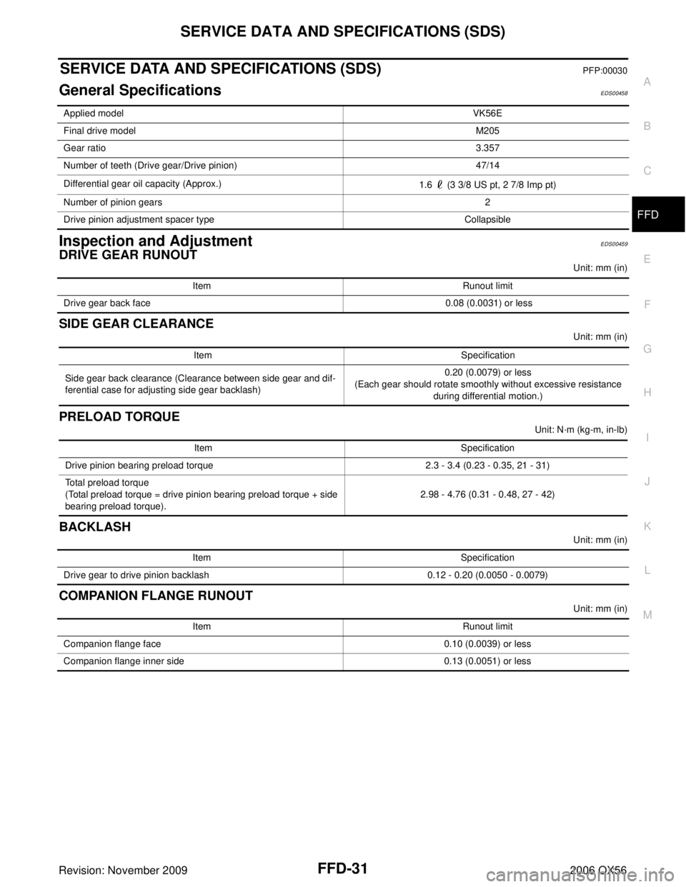
General SpecificationsEDS00458
Inspection and AdjustmentEDS00459
DRIVE GEAR RUNOUT
Unit: mm (in)
SIDE GEAR CLEARANCE
Unit: mm (in)
PRELOAD TORQUE
Unit: N·m (kg-m, in-lb)
BACKLASH
Unit: mm (in)
COMPANION FLANGE RUNOUT
Unit: mm (in)
Applied model
VK56E
Final drive model M205
Gear ratio 3.357
Number of teeth (Drive gear/Drive pinion) 47/14
Differential gear oil capacity (Approx.) 1.6 (3 3/8 US pt, 2 7/8 Imp pt)
Number of pinion gears 2
Drive pinion adjustment spacer type Collapsible
ItemRunout limit
Drive gear back face 0.08 (0.0031) or less
ItemSpecification
Side gear back clearance (Clearance between side gear and dif-
ferential case for adjusting side gear backlash) 0.20 (0.0079) or less
(Each gear should rotate smoothly without excessive resistance during differential motion.)
Item Specification
Drive pinion bearing preload torque 2.3 - 3.4 (0.23 - 0.35, 21 - 31)
Total preload torque
(Total preload torque = drive pinion bearing preload torque + side
bearing preload torque). 2.98 - 4.76 (0.31 - 0.48, 27 - 42)
Item
Specification
Drive gear to drive pinion backlash 0.12 - 0.20 (0.0050 - 0.0079)
ItemRunout limit
Companion flange face 0.10 (0.0039) or less
Companion flange inner side 0.13 (0.0051) or less
Page 2055 of 3383
FFD-32
SERVICE DATA AND SPECIFICATIONS (SDS)
Revision: November 20092006 QX56
SELECTIVE PARTS
Drive Pinion Height Adjusting Washer
Unit: mm (in)
*Always check with the Parts Department for the latest parts information.
Side Gear Thrust Washer
Unit: mm (in)
*: Always check with the Parts Department for the latest parts information. Thickness Package part number*
1.22 (0.048)
1.24 (0.049)
1.27 (0.050)
1.30 (0.051)
1.32 (0.052) 38154 8S111
1.35 (0.053)
1.37 (0.054)
1.40 (0.055)
1.42 (0.056)
1.45 (0.057) 38154 8S112
1.47 (0.058)
1.50 (0.059)
1.52 (0.060)
1.55 (0.061)
1.57 (0.062) 38154 8S113
1.60 (0.063)
1.63 (0.064)
1.65 (0.065)
1.68 (0.066)
1.70 (0.067) 38154 8S114
1.73 (0.068)
1.75 (0.069)
1.78 (0.070)
1.80 (0.071)
1.83 (0.072) 38154 8S115
Thickness
Package part number*
0.76 (0.030)
0.79 (0.031)
0.81 (0.032)
0.84 (0.033)
0.87 (0.034) 38424 8S111
0.89 (0.035)
0.91 (0.036)
0.94 (0.037)
0.97 (0.038)
0.99 (0.039) 38424 8S112