2006 INFINITI M35 battery
[x] Cancel search: batteryPage 2995 of 5621
![INFINITI M35 2006 Factory Service Manual EC-1452
[VK45DE]
ASCD BRAKE SWITCH
Revision: 2006 January2006 M35/M45
2. CHECK OVERALL FUNCTION-II
With CONSULT-II
Check “BRAKE SW2” indication in “DATA MONITOR” mode.
Without CONSULT-II
Ch INFINITI M35 2006 Factory Service Manual EC-1452
[VK45DE]
ASCD BRAKE SWITCH
Revision: 2006 January2006 M35/M45
2. CHECK OVERALL FUNCTION-II
With CONSULT-II
Check “BRAKE SW2” indication in “DATA MONITOR” mode.
Without CONSULT-II
Ch](/manual-img/42/57023/w960_57023-2994.png)
EC-1452
[VK45DE]
ASCD BRAKE SWITCH
Revision: 2006 January2006 M35/M45
2. CHECK OVERALL FUNCTION-II
With CONSULT-II
Check “BRAKE SW2” indication in “DATA MONITOR” mode.
Without CONSULT-II
Check voltage between ECM terminal 101 and ground under the following conditions.
OK or NG
OK >>INSPECTION END
NG >> GO TO 8.
CONDITION INDICATION
Brake pedal: Fully released OFF
Brake pedal: Slightly depressed ON
SEC013D
CONDITION VOLTAGE
Brake pedal: Fully released Approximately 0V
Brake pedal: Slightly depressed Battery voltage
PBIB1537E
Page 2996 of 5621
![INFINITI M35 2006 Factory Service Manual ASCD BRAKE SWITCH
EC-1453
[VK45DE]
C
D
E
F
G
H
I
J
K
L
MA
EC
Revision: 2006 January2006 M35/M45
3. CHECK ASCD BRAKE SWITCH POWER SUPPLY CIRCUIT
1. Turn ignition switch OFF.
2. Disconnect ASCD brake sw INFINITI M35 2006 Factory Service Manual ASCD BRAKE SWITCH
EC-1453
[VK45DE]
C
D
E
F
G
H
I
J
K
L
MA
EC
Revision: 2006 January2006 M35/M45
3. CHECK ASCD BRAKE SWITCH POWER SUPPLY CIRCUIT
1. Turn ignition switch OFF.
2. Disconnect ASCD brake sw](/manual-img/42/57023/w960_57023-2995.png)
ASCD BRAKE SWITCH
EC-1453
[VK45DE]
C
D
E
F
G
H
I
J
K
L
MA
EC
Revision: 2006 January2006 M35/M45
3. CHECK ASCD BRAKE SWITCH POWER SUPPLY CIRCUIT
1. Turn ignition switch OFF.
2. Disconnect ASCD brake switch (2) harness connector.
–Stop lamp switch (1)
3. Turn ignition switch ON.
4. Check voltage between ASCD brake switch terminal 1 and
ground with CONSULT-II or tester.
OK or NG
OK >> GO TO 5.
NG >> GO TO 4.
4. DETECT MALFUNCTIONING PART
Check the following.
Fuse block (J/B) connector E102
10A fuse
Harness for open or short between ASCD brake switch and fuse
>> Repair open circuit or short to ground or short to power in harness or connectors.
5. CHECK ASCD BRAKE SWITCH INPUT SIGNAL CIRCUIT FOR OPEN AND SHORT
1. Turn ignition switch OFF.
2. Disconnect ECM harness connector.
3. Check harness continuity between ECM terminal 108 and ASCD brake switch terminal 2.
Refer to Wiring Diagram.
4. Also check harness for short to ground and short to power.
OK or NG
OK >> GO TO 7.
NG >> GO TO 6.
6. DETECT MALFUNCTIONING PART
Check the following.
Harness connectors E108, M15
Harness for open or short between ECM and ASCD brake switch
>> Repair open circuit or short to ground or short to power in harness or connectors.
PBIB2705E
Voltage: Battery voltage
PBIB0857E
Continuity should exist.
Page 2997 of 5621
![INFINITI M35 2006 Factory Service Manual EC-1454
[VK45DE]
ASCD BRAKE SWITCH
Revision: 2006 January2006 M35/M45
7. CHECK ASCD BRAKE SWITCH
Refer to EC-1318, "
Component Inspection"
OK or NG
OK >> GO TO 13.
NG >> Replace ASCD brake s INFINITI M35 2006 Factory Service Manual EC-1454
[VK45DE]
ASCD BRAKE SWITCH
Revision: 2006 January2006 M35/M45
7. CHECK ASCD BRAKE SWITCH
Refer to EC-1318, "
Component Inspection"
OK or NG
OK >> GO TO 13.
NG >> Replace ASCD brake s](/manual-img/42/57023/w960_57023-2996.png)
EC-1454
[VK45DE]
ASCD BRAKE SWITCH
Revision: 2006 January2006 M35/M45
7. CHECK ASCD BRAKE SWITCH
Refer to EC-1318, "
Component Inspection"
OK or NG
OK >> GO TO 13.
NG >> Replace ASCD brake switch.
8. CHECK STOP LAMP SWITCH POWER SUPPLY CIRCUIT
1. Turn ignition switch OFF.
2. Disconnect stop lamp switch (1) harness connector.
–ASCD brake switch (2)
3. Check voltage between stop lamp switch terminal 1 and ground
with CONSULT -II or tester.
OK or NG
OK >> GO TO 10.
NG >> GO TO 9.
9. DETECT MALFUNCTIONING PART
Check the following.
Fuse block (J/B) connector E101
10A fuse
Harness for open or short between stop lamp switch and battery
>> Repair open circuit or short to ground or short to power in harness or connectors.
10. CHECK STOP LAMP SWITCH INPUT SIGNAL CIRCUIT FOR OPEN AND SHORT
1. Disconnect ECM harness connector.
2. Check harness continuity between ECM terminal 101 and stop lamp switch terminal 2.
Refer to Wiring Diagram.
3. Also check harness for short to ground and short to power.
OK or NG
OK >> GO TO 12.
NG >> GO TO 11.
PBIB2705E
Voltage: Battery voltage
PBIA9488J
Continuity should exist.
Page 3004 of 5621
![INFINITI M35 2006 Factory Service Manual SERVICE DATA AND SPECIFICATIONS (SDS)
EC-1461
[VK45DE]
C
D
E
F
G
H
I
J
K
L
MA
EC
Revision: 2006 January2006 M35/M45
SERVICE DATA AND SPECIFICATIONS (SDS)PFP:00030
Fuel PressureNBS005QT
Idle Speed and INFINITI M35 2006 Factory Service Manual SERVICE DATA AND SPECIFICATIONS (SDS)
EC-1461
[VK45DE]
C
D
E
F
G
H
I
J
K
L
MA
EC
Revision: 2006 January2006 M35/M45
SERVICE DATA AND SPECIFICATIONS (SDS)PFP:00030
Fuel PressureNBS005QT
Idle Speed and](/manual-img/42/57023/w960_57023-3003.png)
SERVICE DATA AND SPECIFICATIONS (SDS)
EC-1461
[VK45DE]
C
D
E
F
G
H
I
J
K
L
MA
EC
Revision: 2006 January2006 M35/M45
SERVICE DATA AND SPECIFICATIONS (SDS)PFP:00030
Fuel PressureNBS005QT
Idle Speed and Ignition TimingNBS005QU
*: Under the following conditions:
Air conditioner switch: OFF
Electric load: OFF (Lights, heater fan & rear window defogger)
Steering wheel: Kept in straight-ahead position
Calculated Load ValueNBS005QV
Mass Air Flow SensorNBS005QW
*: Engine is warmed up to normal operating temperature and running under no load.
Intake Air Temperature SensorNBS005QX
Engine Coolant Temperature SensorNBS005QY
Fuel Tank Temperature SensorNBS005QZ
Crankshaft Position Sensor (POS)NBS005R0
Refer to EC-1105, "Component Inspection" .
Camshaft Position Sensor (PHASE)NBS005R1
Refer to EC-1112, "Component Inspection" .
A/F Sensor 1 HeaterNBS005R2
Fuel pressure at idling kPa (kg/cm2 , psi)Approximately 350 (3.57, 51)
Target idle speed No load* (in P or N position) 65050 rpm
Air conditioner: ON In P or N position 650 rpm or more
Ignition timing In P or N position 12
5 BTDC
Condition Calculated load value% (Using CONSULT-II or GST)
At idle14 - 33
At 2,500 rpm12 - 25
Supply voltageBattery voltage (11 - 14V)
Output voltage at idle0.9 - 1.2V*
Mass air flow (Using CONSULT-II or GST)2.0 - 6.0 gꞏm/sec at idle*
7.0 - 20.0 gꞏm/sec at 2,500 rpm*
Temperature C (F) Resistance k
25 (77)1.800 - 2.200
Temperature C (F) Resistance k
20 (68)2.1 - 2.9
50 (122)0.68 - 1.00
90 (194)0.236 - 0.260
Temperature C (F) Resistance k
20 (68)2.3 - 2.7
50 (122)0.79 - 0.90
Resistance [at 25C (77F)] 2.3 - 4.3
Page 3023 of 5621

EI-18
COWL TOP
Revision: 2006 January2006 M35/M45
COWL TOPPFP:66100
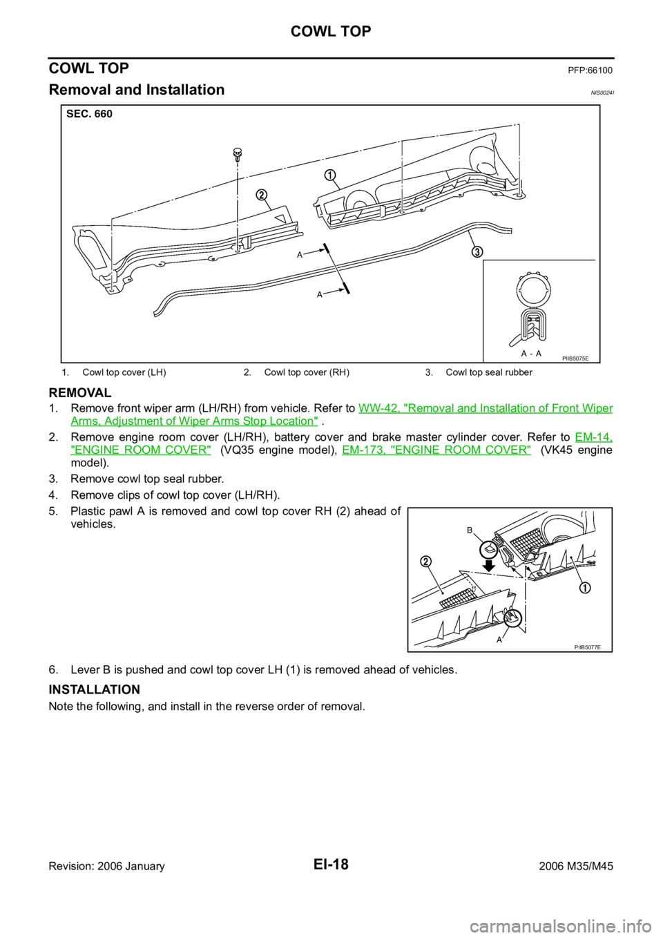
Removal and InstallationNIS0024I
REMOVAL
1. Remove front wiper arm (LH/RH) from vehicle. Refer to WW-42, "Removal and Installation of Front Wiper
Arms, Adjustment of Wiper Arms Stop Location" .
2. Remove engine room cover (LH/RH), battery cover and brake master cylinder cover. Refer to EM-14,
"ENGINE ROOM COVER" (VQ35 engine model), EM-173, "ENGINE ROOM COVER" (VK45 engine
model).
3. Remove cowl top seal rubber.
4. Remove clips of cowl top cover (LH/RH).
5. Plastic pawl A is removed and cowl top cover RH (2) ahead of
vehicles.
6. Lever B is pushed and cowl top cover LH (1) is removed ahead of vehicles.
INSTALLATION
Note the following, and install in the reverse order of removal.
1. Cowl top cover (LH) 2. Cowl top cover (RH) 3. Cowl top seal rubber
PIIB5075E
PIIB5077E
Page 3054 of 5621

SUNSHADE
EI-49
C
D
E
F
G
H
J
K
L
MA
B
EI
Revision: 2006 January2006 M35/M45
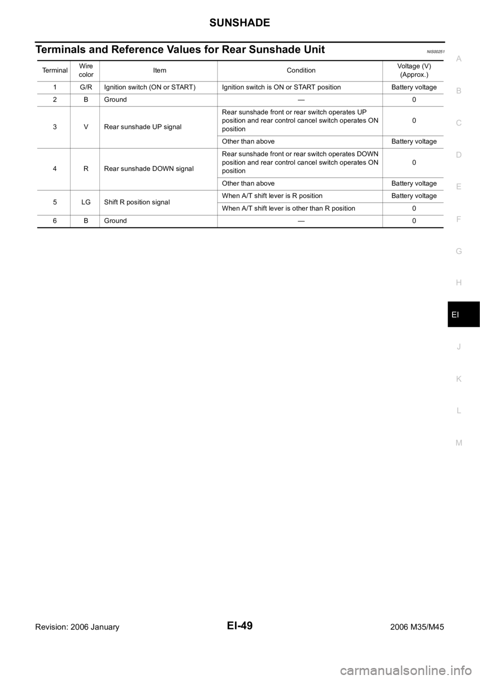
Terminals and Reference Values for Rear Sunshade UnitNIS00251
TerminalWire
colorItem ConditionVoltage (V)
(Approx.)
1 G/R Ignition switch (ON or START) Ignition switch is ON or START position Battery voltage
2 B Ground — 0
3 V Rear sunshade UP signalRear sunshade front or rear switch operates UP
position and rear control cancel switch operates ON
position0
Other than above Battery voltage
4 R Rear sunshade DOWN signalRear sunshade front or rear switch operates DOWN
position and rear control cancel switch operates ON
position0
Other than above Battery voltage
5 LG Shift R position signalWhen A/T shift lever is R position Battery voltage
When A/T shift lever is other than R position 0
6 B Ground — 0
Page 3064 of 5621

EM-1
ENGINE MECHANICAL
B ENGINE
CONTENTS
C
D
E
F
G
H
I
J
K
L
M
SECTION EM
A
EM
Revision: 2006 January2006 M35/M45
ENGINE MECHANICAL
VQ35DE
PRECAUTIONS .......................................................... 5
Precautions for Procedures without Cowl Top Cover ..... 5
Precautions Necessary for Steering Wheel Rotation
After Battery Disconnect .......................................... 5
OPERATION PROCEDURE ................................. 5
Precautions for Drain Engine Coolant and Engine
Oil ............................................................................. 5
Precautions for Disconnecting Fuel Piping .............. 5
Precautions for Removal and Disassembly ............. 5
Precautions for Inspection, Repair and Replace-
ment ......................................................................... 6
Precautions for Assembly and Installation ............... 6
Precautions for Angle Tightening ............................. 6
Precautions for Liquid Gasket .................................. 6
REMOVAL OF LIQUID GASKET SEALING .......... 6
LIQUID GASKET APPLICATION PROCEDURE ..... 7
PREPARATION ........................................................... 8
Special Service Tools ............................................... 8
Commercial Service Tools ...................................... 10
NOISE, VIBRATION AND HARSHNESS (NVH)
TROUBLESHOOTING .............................................. 12
NVH Troubleshooting — Engine Noise .................. 12
Use the Chart Below to Help You Find the Cause
of the Symptom. ..................................................... 13
ENGINE ROOM COVER .......................................... 14
Components ........................................................... 14
Removal and Installation ........................................ 14
REMOVAL ........................................................
... 14
INSTALLATION ................................................... 14
DRIVE BELTS ........................................................... 15
Checking Drive Belts .............................................. 15
Tension Adjustment ................................................ 15
ALTERNATOR AND POWER STEERING OIL
PUMP BELT ........................................................ 16
A/C COMPRESSOR BELT ................................. 16
Removal and Installation ........................................ 16
REMOVAL ........................................................
... 16
INSTALLATION ................................................... 16AIR CLEANER AND AIR DUCT ............................... 17
Components ........................................................... 17
Removal and Installation ........................................ 17
REMOVAL ........................................................
... 17
INSTALLATION ................................................... 17
Changing Air Cleaner Filter .................................... 18
REMOVAL ........................................................
... 18
INSTALLATION ................................................... 18
INTAKE MANIFOLD COLLECTOR .......................... 19
Components ........................................................... 19
Removal and Installation ........................................ 19
REMOVAL ........................................................
... 19
INSPECTION AFTER REMOVAL ....................... 21
INSTALLATION ................................................... 22
INTAKE MANIFOLD ................................................. 24
Components ........................................................... 24
Removal and Installation ........................................ 24
REMOVAL ........................................................
... 24
INSPECTION AFTER REMOVAL ....................... 25
INSTALLATION ................................................... 25
EXHAUST MANIFOLD ............................................. 26
Components ........................................................... 26
Removal and Installation ........................................ 26
REMOVAL ........................................................
... 26
INSPECTION AFTER REMOVAL ....................... 27
INSTALLATION ................................................... 27
OIL PAN AND OIL STRAINER ................................. 29
Components (2WD Models) ................................... 29
Removal and Installation (2WD Models) ................ 29
REMOVAL ........................................................
... 29
INSPECTION AFTER REMOVAL ....................... 31
INSTALLATION ................................................... 31
INSPECTION AFTER INSTALLATION ................ 34
Components (AWD Models) ................................... 35
Removal and Installation (AWD Models) ................ 36
REMOVAL ........................................................
... 36
INSPECTION AFTER REMOVAL ....................... 38
INSTALLATION ................................................... 38
INSPECTION AFTER INSTALLATION ................ 41
Page 3066 of 5621

EM-3
C
D
E
F
G
H
I
J
K
L
M
EMA
Revision: 2006 January2006 M35/M45 ANCE ................................................................146
MAIN BEARING OIL CLEARANCE ..................147
MAIN BEARING CRUSH HEIGHT ....................148
CONNECTING ROD BEARING CRUSH
HEIGHT .............................................................148
MAIN BEARING CAP BOLT OUTER DIAMETER .148
CONNECTING ROD BOLT OUTER DIAMETER .149
DRIVE PLATE ...................................................149
OIL JET .............................................................149
OIL JET RELIEF VALVE ...................................149
SERVICE DATA AND SPECIFICATIONS (SDS) ....150
Standard and Limit ...............................................150
GENERAL SPECIFICATIONS ..........................150
DRIVE BELT .....................................................151
INTAKE MANIFOLD COLLECTOR, INTAKE
MANIFOLD AND EXHAUST MANIFOLD .........151
SPARK PLUG ...................................................151
CAMSHAFT AND CAMSHAFT BEARING ........152
CYLINDER HEAD .............................................154
CYLINDER BLOCK ...........................................157
PISTON, PISTON RING AND PISTON PIN ......158
CONNECTING ROD .........................................159
CRANKSHAFT ..................................................160
MAIN BEARING ................................................161
CONNECTING ROD BEARING ........................162
VK45DE
PRECAUTIONS ......................................................163
Precautions for Procedures without Cowl Top Cover .163
Precautions Necessary for Steering Wheel Rotation
After Battery Disconnect ......................................163
OPERATION PROCEDURE .............................163
Precautions for Drain Engine Coolant and Engine
Oil .........................................................................163
Precautions for Disconnecting Fuel Piping ..........163
Precautions for Removal and Disassembly .........163
Precautions for Inspection, Repair and Replace-
ment .....................................................................164
Precautions for Assembly and Installation ...........164
Parts Requiring Angle Tightening .........................164
Precautions for Liquid Gasket ..............................164
REMOVAL OF LIQUID GASKET SEALING ......164
LIQUID GASKET APPLICATION PROCEDURE .165
PREPARATION .......................................................166
Special Service Tools ...........................................166
Commercial Service Tools ....................................169
NOISE, VIBRATION AND HARSHNESS (NVH)
TROUBLESHOOTING ............................................171
NVH Troubleshooting — Engine Noise ................171
Use the Chart Below to Help You Find the Cause
of the Symptom. ...................................................172
ENGINE ROOM COVER ........................................173
Components .........................................................173
Removal and Installation ......................................173
REMOVAL ........................................................
.173
INSTALLATION .................................................173DRIVE BELTS .........................................................174
Components .........................................................174
Checking Drive Belts ............................................174
Tension Adjustment .............................................
.174
Removal and Installation ......................................174
REMOVAL ........................................................
.174
INSTALLATION .................................................175
Components .........................................................176
Drive Belt Auto Tensioner and Idler Pulley ...........176
REMOVAL ........................................................
.176
INSTALLATION .................................................176
AIR CLEANER AND AIR DUCT .............................177
Components .........................................................177
Removal and Installation ......................................177
REMOVAL ........................................................
.177
INSPECTION AFTER REMOVAL .....................178
INSTALLATION .................................................178
Changing Air Cleaner Filter ..................................178
REMOVAL ........................................................
.178
INSTALLATION .................................................178
INTAKE MANIFOLD ..............................................
.179
Components .........................................................179
Removal and Installation ......................................180
REMOVAL ........................................................
.180
INSPECTION AFTER REMOVAL .....................182
INSTALLATION .................................................182
INSPECTION AFTER INSTALLATION ..............182
EXHAUST MANIFOLD AND THREE WAY CATA-
LYST ........................................................................183
Components .........................................................183
Removal and Installation ......................................183
REMOVAL ........................................................
.183
INSPECTION AFTER REMOVAL .....................185
INSTALLATION .................................................185
OIL PAN AND OIL STRAINER ...............................187
Components .........................................................187
Removal and Installation ......................................187
REMOVAL ........................................................
.187
INSPECTION AFTER REMOVAL .....................188
INSTALLATION .................................................188
INSPECTION AFTER INSTALLATION ..............189
IGNITION COIL .......................................................190
Components .........................................................190
Removal and Installation ......................................190
REMOVAL ........................................................
.190
INSTALLATION .................................................190
SPARK PLUG (PLATINUM-TIPPED TYPE) ...........191
Components .........................................................191
Removal and Installation ......................................191
REMOVAL ........................................................
.191
INSPECTION AFTER REMOVAL .....................191
INSTALLATION .................................................192
FUEL INJECTOR AND FUEL TUBE ......................193
Components .........................................................193
Removal and Installation ......................................193
REMOVAL ........................................................
.193
INSTALLATION .................................................195
INSPECTION AFTER INSTALLATION ..............197