2006 INFINITI M35 water pump
[x] Cancel search: water pumpPage 3239 of 5621
![INFINITI M35 2006 Factory Service Manual EM-176
[VK45DE]
DRIVE BELTS
Revision: 2006 January2006 M35/M45
ComponentsNBS004OO
CAUTION:
The complete drive belt auto tensioner must be replaced as a unit, including the pulley.
Drive Belt Auto Tens INFINITI M35 2006 Factory Service Manual EM-176
[VK45DE]
DRIVE BELTS
Revision: 2006 January2006 M35/M45
ComponentsNBS004OO
CAUTION:
The complete drive belt auto tensioner must be replaced as a unit, including the pulley.
Drive Belt Auto Tens](/manual-img/42/57023/w960_57023-3238.png)
EM-176
[VK45DE]
DRIVE BELTS
Revision: 2006 January2006 M35/M45
ComponentsNBS004OO
CAUTION:
The complete drive belt auto tensioner must be replaced as a unit, including the pulley.
Drive Belt Auto Tensioner and Idler PulleyNBS004OP
REMOVAL
1. Remove air duct (inlet). Refer to EM-177, "AIR CLEANER AND AIR DUCT" .
2. Remove front engine undercover with power tool.
3. Remove drive belts. Refer to EM-174, "
Removal and Installation" .
Keep auto tensioner pulley arm locked after belt is removed.
4. Remove auto tensioner and idler pulley with power tool.
Keep auto tensioner pulley arm locked to install or remove auto tensioner.
CAUTION:
Do not loosen the hexagonal part in center of drive belt auto tensioner pulley (Do not turn it clock-
wise). If turned clockwise, the complete drive belt auto tensioner must be replaced as a unit,
including the pulley.
INSTALLATION
Installation is the reverse order of removal.
CAUTION:
Do not swap the pulley between new and old drive belt auto tensioner.
1.Auto tensioner (Used for alternator,
water pump and A/C compressor)2. Idler pulley 3.Auto tensioner (Used for power
steering oil pump belt)
PBIC2788E
Page 3267 of 5621
![INFINITI M35 2006 Factory Service Manual EM-204
[VK45DE]
TIMING CHAIN
Revision: 2006 January2006 M35/M45
Removal and InstallationNBS004P8
REMOVAL
1. Remove engine assembly from vehicle. Refer to EM-244, "ENGINE ASSEMBLY" .
2. Remove INFINITI M35 2006 Factory Service Manual EM-204
[VK45DE]
TIMING CHAIN
Revision: 2006 January2006 M35/M45
Removal and InstallationNBS004P8
REMOVAL
1. Remove engine assembly from vehicle. Refer to EM-244, "ENGINE ASSEMBLY" .
2. Remove](/manual-img/42/57023/w960_57023-3266.png)
EM-204
[VK45DE]
TIMING CHAIN
Revision: 2006 January2006 M35/M45
Removal and InstallationNBS004P8
REMOVAL
1. Remove engine assembly from vehicle. Refer to EM-244, "ENGINE ASSEMBLY" .
2. Remove the following components and related parts:
Drive belt auto tensioner and idler pulley; Refer to EM-176, "Drive Belt Auto Tensioner and Idler Pulley"
.
Thermostat housing and hoses; Refer to CO-55, "THERMOSTAT AND WATER CONTROL VALVE" .
Ignition coil; Refer to EM-190, "IGNITION COIL" .
Rocker cover; Refer to EM-199, "ROCKER COVER" .
3. If necessary, remove intake valve timing control position sensor
(right and left bank) and camshaft position sensor (PHASE) from
intake valve timing control cover and front cover.
CAUTION:
Handle carefully to avoid dropping and shocks.
Do not disassemble.
4. If necessary, remove intake valve timing control solenoid valve from intake valve timing control cover.
CAUTION:
Handle components and parts carefully to avoid dropping and shocks.
Do not disassemble.
Do not allow metal powder to adhere to magnetic part at sensor tip.
Do not place sensors in a location where they are exposed to magnetism.
1. Camshaft sprocket (EXH) 2. Camshaft sprocket (INT) 3. Camshaft sprocket (INT)
4. Camshaft sprocket (EXH) 5. Front cover 6.Intake valve timing control solenoid
valve (right bank)
7. O-ring 8. Seal ring 9.Intake valve timing control position
sensor (right bank)
10. O-ring 11.Intake valve timing control cover
(right bank)12.Intake valve timing control position
sensor (left bank)
13. O-ring 14.Intake valve timing control cover (left
bank)15. Seal ring
16.Intake valve timing control solenoid
valve (left bank)17. O-ring 18. Oil level gauge
19. Oil level gauge guide 20. O-ring 21. Crankshaft pulley bolt
22. Crankshaft pulley 23. Front oil seal 24. Chain tensioner cover
25. Camshaft position sensor (PHASE) 26. O-ring 27. Oil pump drive spacer
28. Oil pump assembly 29. Crankshaft sprocket 30. O-ring
31. O-ring 32.Timing chain tension guide
(right bank)33.Timing chain slack guide
(right bank)
34. Timing chain (right bank) 35. Timing chain (left bank) 36. Chain tensioner (left bank)
37. Chain tensioner (right bank) 38.Timing chain slack guide
(left bank)39.Timing chain tension guide
(left bank)
40. O-ring
PBIC0050E
Page 3468 of 5621
PRECAUTIONS
GI-5
C
D
E
F
G
H
I
J
K
L
MB
GI
Revision: 2006 January2006 M35/M45
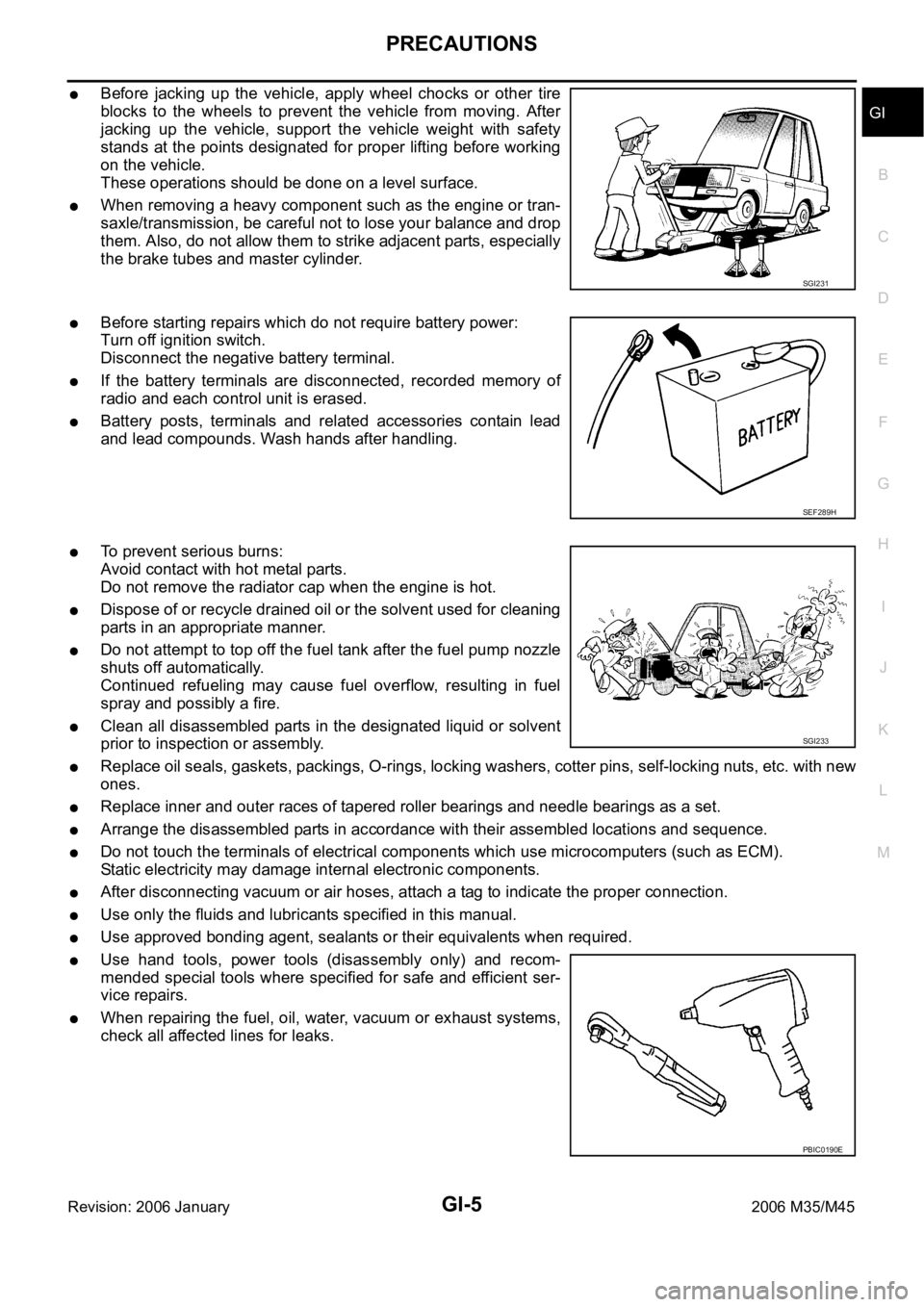
Before jacking up the vehicle, apply wheel chocks or other tire
blocks to the wheels to prevent the vehicle from moving. After
jacking up the vehicle, support the vehicle weight with safety
stands at the points designated for proper lifting before working
on the vehicle.
These operations should be done on a level surface.
When removing a heavy component such as the engine or tran-
saxle/transmission, be careful not to lose your balance and drop
them. Also, do not allow them to strike adjacent parts, especially
the brake tubes and master cylinder.
Before starting repairs which do not require battery power:
Turn off ignition switch.
Disconnect the negative battery terminal.
If the battery terminals are disconnected, recorded memory of
radio and each control unit is erased.
Battery posts, terminals and related accessories contain lead
and lead compounds. Wash hands after handling.
To prevent serious burns:
Avoid contact with hot metal parts.
Do not remove the radiator cap when the engine is hot.
Dispose of or recycle drained oil or the solvent used for cleaning
parts in an appropriate manner.
Do not attempt to top off the fuel tank after the fuel pump nozzle
shuts off automatically.
Continued refueling may cause fuel overflow, resulting in fuel
spray and possibly a fire.
Clean all disassembled parts in the designated liquid or solvent
prior to inspection or assembly.
Replace oil seals, gaskets, packings, O-rings, locking washers, cotter pins, self-locking nuts, etc. with new
ones.
Replace inner and outer races of tapered roller bearings and needle bearings as a set.
Arrange the disassembled parts in accordance with their assembled locations and sequence.
Do not touch the terminals of electrical components which use microcomputers (such as ECM).
Static electricity may damage internal electronic components.
After disconnecting vacuum or air hoses, attach a tag to indicate the proper connection.
Use only the fluids and lubricants specified in this manual.
Use approved bonding agent, sealants or their equivalents when required.
Use hand tools, power tools (disassembly only) and recom-
mended special tools where specified for safe and efficient ser-
vice repairs.
When repairing the fuel, oil, water, vacuum or exhaust systems,
check all affected lines for leaks.
SGI231
SEF289H
SGI233
PBIC0190E
Page 3531 of 5621
GW-12
WINDSHIELD GLASS
Revision: 2006 January2006 M35/M45
4. Remove the cowl top cover. Refer to EI-18, "COWL TOP" .
5. Remove roof side molding. Refer to EI-25, "
ROOF SIDE MOLDING" .
6. Apply a protective tape around the windshield glass to protect the painted surface from damage.
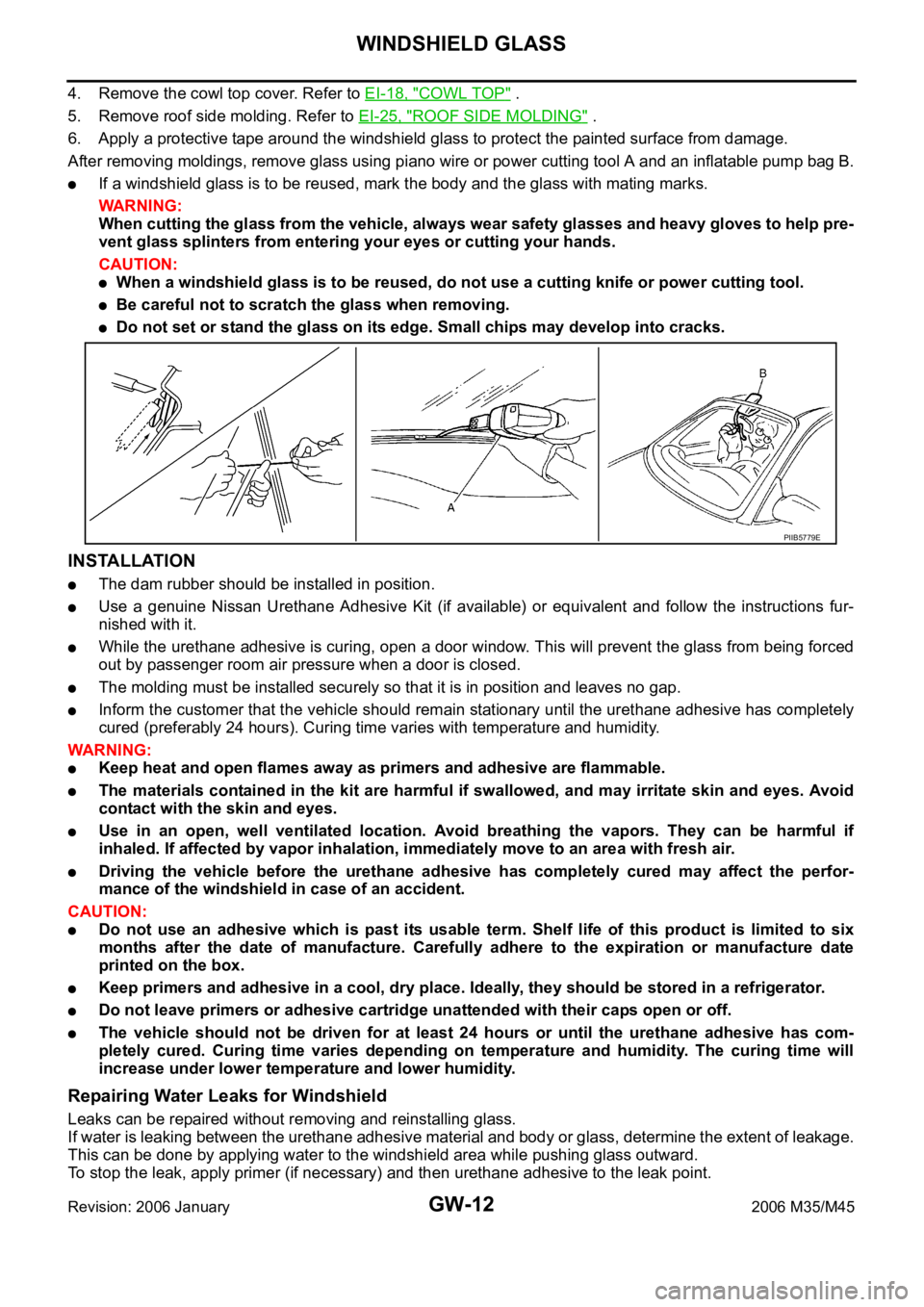
After removing moldings, remove glass using piano wire or power cutting tool A and an inflatable pump bag B.
If a windshield glass is to be reused, mark the body and the glass with mating marks.
WA R N I N G :
When cutting the glass from the vehicle, always wear safety glasses and heavy gloves to help pre-
vent glass splinters from entering your eyes or cutting your hands.
CAUTION:
When a windshield glass is to be reused, do not use a cutting knife or power cutting tool.
Be careful not to scratch the glass when removing.
Do not set or stand the glass on its edge. Small chips may develop into cracks.
INSTALLATION
The dam rubber should be installed in position.
Use a genuine Nissan Urethane Adhesive Kit (if available) or equivalent and follow the instructions fur-
nished with it.
While the urethane adhesive is curing, open a door window. This will prevent the glass from being forced
out by passenger room air pressure when a door is closed.
The molding must be installed securely so that it is in position and leaves no gap.
Inform the customer that the vehicle should remain stationary until the urethane adhesive has completely
cured (preferably 24 hours). Curing time varies with temperature and humidity.
WAR NING :
Keep heat and open flames away as primers and adhesive are flammable.
The materials contained in the kit are harmful if swallowed, and may irritate skin and eyes. Avoid
contact with the skin and eyes.
Use in an open, well ventilated location. Avoid breathing the vapors. They can be harmful if
inhaled. If affected by vapor inhalation, immediately move to an area with fresh air.
Driving the vehicle before the urethane adhesive has completely cured may affect the perfor-
mance of the windshield in case of an accident.
CAUTION:
Do not use an adhesive which is past its usable term. Shelf life of this product is limited to six
months after the date of manufacture. Carefully adhere to the expiration or manufacture date
printed on the box.
Keep primers and adhesive in a cool, dry place. Ideally, they should be stored in a refrigerator.
Do not leave primers or adhesive cartridge unattended with their caps open or off.
The vehicle should not be driven for at least 24 hours or until the urethane adhesive has com-
pletely cured. Curing time varies depending on temperature and humidity. The curing time will
increase under lower temperature and lower humidity.
Repairing Water Leaks for Windshield
Leaks can be repaired without removing and reinstalling glass.
If water is leaking between the urethane adhesive material and body or glass, determine the extent of leakage.
This can be done by applying water to the windshield area while pushing glass outward.
To stop the leak, apply primer (if necessary) and then urethane adhesive to the leak point.
PIIB5779E
Page 3649 of 5621
IDX-8
ALPHABETICAL INDEX
U
Unified meter and A/C amp. ............................... DI-28
Upper link (front susp.) ..................... FSU-16, FSU-33
V
Vacuum hose (brake system) ............................ BR-21
Valve clearance(VK45DE) .............................. EM-222
Valve clearance(VQ35DE) ................................ EM-93
Valve guide ..................................................... EM-108
Valve guide(VK45DE) ..................................... EM-240
Valve lifter ......................................................... EM-88
Valve seat(VK45DE) ....................................... EM-242
Valve seat(VQ35DE) ...................................... EM-110
Valve spring(VK45DE) .................................... EM-243
Valve spring(VQ35DE) ................................... EM-111
Variable induction air control system (VIAS) EC-1324,
EC-1398
Vehicle security (theft warning) system ........... BL-220
Vehicle speed sensor (VSS) ............. EC-481, EC-597,
EC-1200
VEHSEC - Wiring diagram ............................... BL-226
VENT/V - Wiring diagram EC-429, EC-436, EC-1149,
EC-1156
VIAS - Wiring diagram ................................... EC-1400
VIAS/V - Wiring diagram ................................ EC-1325
VIN registration .................................... EC-95, EC-806
VSS A/T - Wiring diagram ................................ AT-121
W
WARN - Wiring diagram ..................................... DI-43
Warning chime .................................................... DI-60
Warning lamps .................................................... DI-40
Washer, front ..................................................... WW-4
Water control valve(VK45DE) ........................... CO-55
Water pump(VK45DE) ...................................... CO-53
Water pump(VQ35DE) ...................................... CO-24
Water temperature gauge ..................................... DI-5
Wheel alignment (front) ...................... FSU-6, FSU-23
Wheel alignment (rear) ..................................... RSU-5
Wheel balance ........................................ WT-7, MA-33
Wheel bearing (rear) ......................................... RAX-5
Wheel hub (rear) ............................................... RAX-5
Wheel sensor (VDC) ....................................... BRC-57
WINDOW - Wiring diagram ............................... GW-21
Window, door ...................................... GW-63, GW-67
Window, rear ..................................................... GW-61
Windshield ........................................................ GW-11
WIPER - Wiring diagram .................................. WW-13
Wiper, front ........................................................ WW-4
Wiring Diagram (Cell code) list .......................... PG-93
Wiring diagrams .................................................. GI-16
Page 4750 of 5621
![INFINITI M35 2006 Factory Service Manual ENGINE OIL
LU-7
[VQ35DE]
C
D
E
F
G
H
I
J
K
L
MA
LU
Revision: 2006 January2006 M35/M45
ENGINE OILPFP:KLA92
InspectionNBS004PW
ENGINE OIL LEVEL
NOTE:
Before starting engine, put vehicle horizontally and INFINITI M35 2006 Factory Service Manual ENGINE OIL
LU-7
[VQ35DE]
C
D
E
F
G
H
I
J
K
L
MA
LU
Revision: 2006 January2006 M35/M45
ENGINE OILPFP:KLA92
InspectionNBS004PW
ENGINE OIL LEVEL
NOTE:
Before starting engine, put vehicle horizontally and](/manual-img/42/57023/w960_57023-4749.png)
ENGINE OIL
LU-7
[VQ35DE]
C
D
E
F
G
H
I
J
K
L
MA
LU
Revision: 2006 January2006 M35/M45
ENGINE OILPFP:KLA92
InspectionNBS004PW
ENGINE OIL LEVEL
NOTE:
Before starting engine, put vehicle horizontally and check the engine oil level. If engine is already started, stop
it and allow 10 minutes before checking.
1. Pull out oil level gauge and wipe it clean.
2. Insert oil level gauge and make sure the engine oil level is within
the range shown in the figure.
3. If it is out of range, adjust it.
NOTE:
When checking the engine oil level, insert oil level gauge with its
tip aligned with oil level gauge guide on cylinder head. (In figure,
air cleaner case and air duct are removed.)
ENGINE OIL APPEARANCE
Check engine oil for white turbidity or heavy contamination.
If engine oil becomes turbid and white, it is highly probable that it is contaminated with engine coolant.
Repair or replace damaged parts.
ENGINE OIL LEAKAGE
Check for engine oil leakage around the following areas:
Oil pans (lower and upper)
Oil pan drain plug
Oil pressure switch
Oil filter
Oil filter bracket (AWD models)
Oil cooler
Water pump cover
Chain tensioner cover
Intake valve timing control cover and intake valve timing control solenoid valve
Mating surface between cylinder head and rocker cover
Mating surface between front timing chain case and rear timing chain case
Mating surface between rear timing chain case and cylinder head
Mating surface between rear timing chain case and cylinder block
Mating surface between rear timing chain case and oil pan (upper)
Mating surface between cylinder block and cylinder head
PBIC0249E
KBIA1343E
Page 4799 of 5621
MA-22
ENGINE MAINTENANCE (VK45DE ENGINE)
Revision: 2006 January2006 M35/M45
ENGINE MAINTENANCE (VK45DE ENGINE)PFP:10001
Checking Drive BeltsNLS0007Q
WAR NING :
Be sure to perform when the engine is stopped.
Remove air duct (inlet) when inspecting drive belt for alternator, water pump and A/C compressor.
Remove front engine undercover with power tool when inspecting power steering oil pump belt.
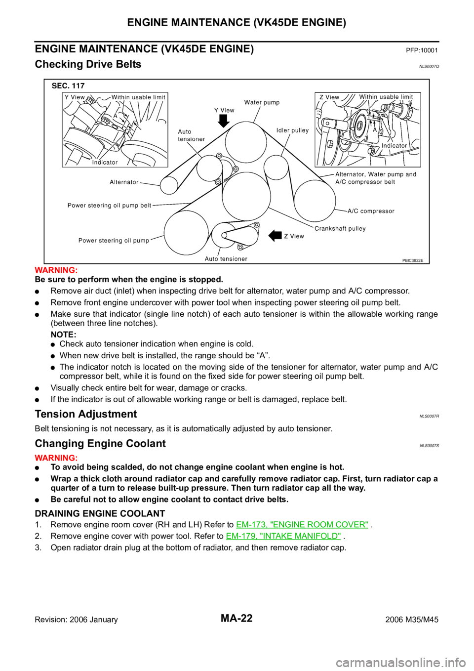
Make sure that indicator (single line notch) of each auto tensioner is within the allowable working range
(between three line notches).
NOTE:
Check auto tensioner indication when engine is cold.
When new drive belt is installed, the range should be “A”.
The indicator notch is located on the moving side of the tensioner for alternator, water pump and A/C
compressor belt, while it is found on the fixed side for power steering oil pump belt.
Visually check entire belt for wear, damage or cracks.
If the indicator is out of allowable working range or belt is damaged, replace belt.
Te n s i o n A d j u s t m e n tNLS0007R
Belt tensioning is not necessary, as it is automatically adjusted by auto tensioner.
Changing Engine CoolantNLS0007S
WAR NING :
To avoid being scalded, do not change engine coolant when engine is hot.
Wrap a thick cloth around radiator cap and carefully remove radiator cap. First, turn radiator cap a
quarter of a turn to release built-up pressure. Then turn radiator cap all the way.
Be careful not to allow engine coolant to contact drive belts.
DRAINING ENGINE COOLANT
1. Remove engine room cover (RH and LH) Refer to EM-173, "ENGINE ROOM COVER" .
2. Remove engine cover with power tool. Refer to EM-179, "
INTAKE MANIFOLD" .
3. Open radiator drain plug at the bottom of radiator, and then remove radiator cap.
PBIC3822E
Page 5176 of 5621
CHARGING SYSTEM
SC-39
C
D
E
F
G
H
I
J
L
MA
B
SC
Revision: 2006 January2006 M35/M45
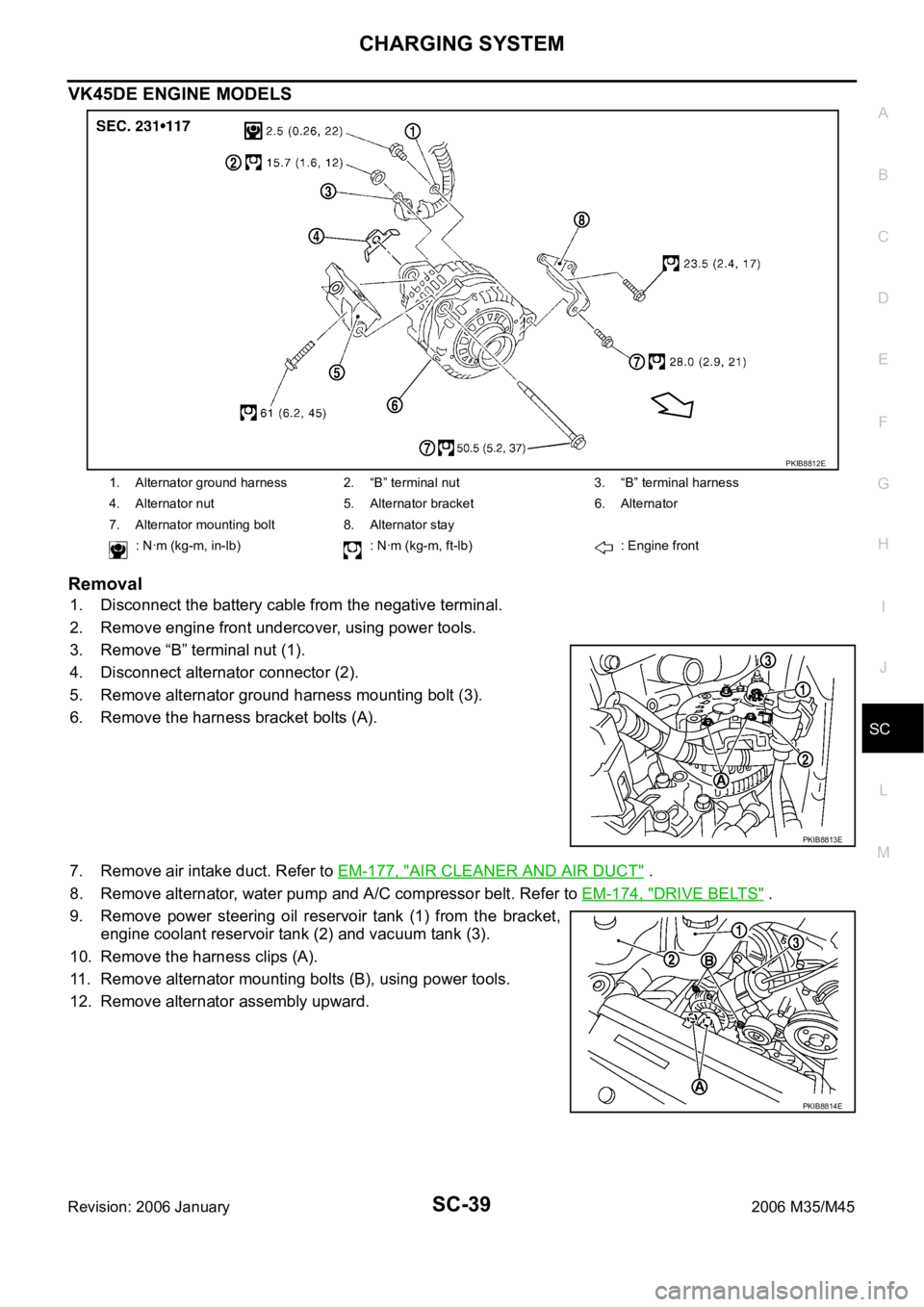
VK45DE ENGINE MODELS
Removal
1. Disconnect the battery cable from the negative terminal.
2. Remove engine front undercover, using power tools.
3. Remove “B” terminal nut (1).
4. Disconnect alternator connector (2).
5. Remove alternator ground harness mounting bolt (3).
6. Remove the harness bracket bolts (A).
7. Remove air intake duct. Refer to EM-177, "
AIR CLEANER AND AIR DUCT" .
8. Remove alternator, water pump and A/C compressor belt. Refer to EM-174, "
DRIVE BELTS" .
9. Remove power steering oil reservoir tank (1) from the bracket,
engine coolant reservoir tank (2) and vacuum tank (3).
10. Remove the harness clips (A).
11. Remove alternator mounting bolts (B), using power tools.
12. Remove alternator assembly upward.
1. Alternator ground harness 2. “B” terminal nut 3. “B” terminal harness
4. Alternator nut 5. Alternator bracket 6. Alternator
7. Alternator mounting bolt 8. Alternator stay
: Nꞏm (kg-m, in-lb) : Nꞏm (kg-m, ft-lb) : Engine front
PKIB8812E
PKIB8813E
PKIB8814E