2006 INFINITI M35 drain bolt
[x] Cancel search: drain boltPage 4792 of 5621
ENGINE MAINTENANCE (VQ35DE ENGINE)
MA-15
C
D
E
F
G
H
I
J
K
MA
B
MA
Revision: 2006 January2006 M35/M45
ALTERNATOR AND POWER STEERING OIL PUMP BELT
1. Remove front engine undercover with power tool.
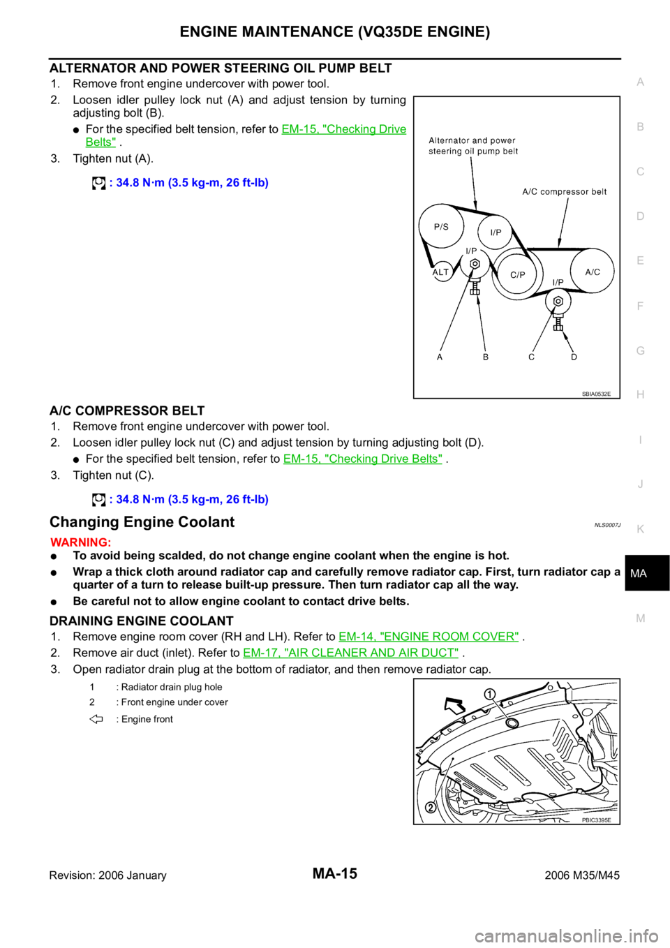
2. Loosen idler pulley lock nut (A) and adjust tension by turning
adjusting bolt (B).
For the specified belt tension, refer to EM-15, "Checking Drive
Belts" .
3. Tighten nut (A).
A/C COMPRESSOR BELT
1. Remove front engine undercover with power tool.
2. Loosen idler pulley lock nut (C) and adjust tension by turning adjusting bolt (D).
For the specified belt tension, refer to EM-15, "Checking Drive Belts" .
3. Tighten nut (C).
Changing Engine CoolantNLS0007J
WAR NING :
To avoid being scalded, do not change engine coolant when the engine is hot.
Wrap a thick cloth around radiator cap and carefully remove radiator cap. First, turn radiator cap a
quarter of a turn to release built-up pressure. Then turn radiator cap all the way.
Be careful not to allow engine coolant to contact drive belts.
DRAINING ENGINE COOLANT
1. Remove engine room cover (RH and LH). Refer to EM-14, "ENGINE ROOM COVER" .
2. Remove air duct (inlet). Refer to EM-17, "
AIR CLEANER AND AIR DUCT" .
3. Open radiator drain plug at the bottom of radiator, and then remove radiator cap. : 34.8 Nꞏm (3.5 kg-m, 26 ft-lb)
SBIA0532E
: 34.8 Nꞏm (3.5 kg-m, 26 ft-lb)
1 : Radiator drain plug hole
2 : Front engine under cover
: Engine front
PBIC3395E
Page 4795 of 5621
MA-18
ENGINE MAINTENANCE (VQ35DE ENGINE)
Revision: 2006 January2006 M35/M45
Checking Fuel LinesNLS0007K
Inspect fuel lines, filler cap and tank for improper attachment, leaks,
cracks, damage, loose connections, chafing or deterioration.
If necessary, repair or replace damaged parts.
Changing Air Cleaner FilterNLS0007L
VISCOUS PAPER TYPE
The viscous paper type filter does not need cleaning between replacement intervals. Refer to MA-7,
"PERIODIC MAINTENANCE" .
Changing Engine OilNLS0007M
WAR NING :
Be careful not to burn yourself, as engine oil may be hot.
Prolonged and repeated contact with used engine oil may cause skin cancer; try to avoid direct
skin contact with used engine oil. If skin contact is made, wash thoroughly with soap or hand
cleaner as soon as possible.
1. Warm up the engine, and check for engine oil leakage from engine components. Refer to LU-7, "
ENGINE
OIL LEAKAGE" .
2. Stop the engine and wait for 10 minutes.
3. Loosen oil filler cap.
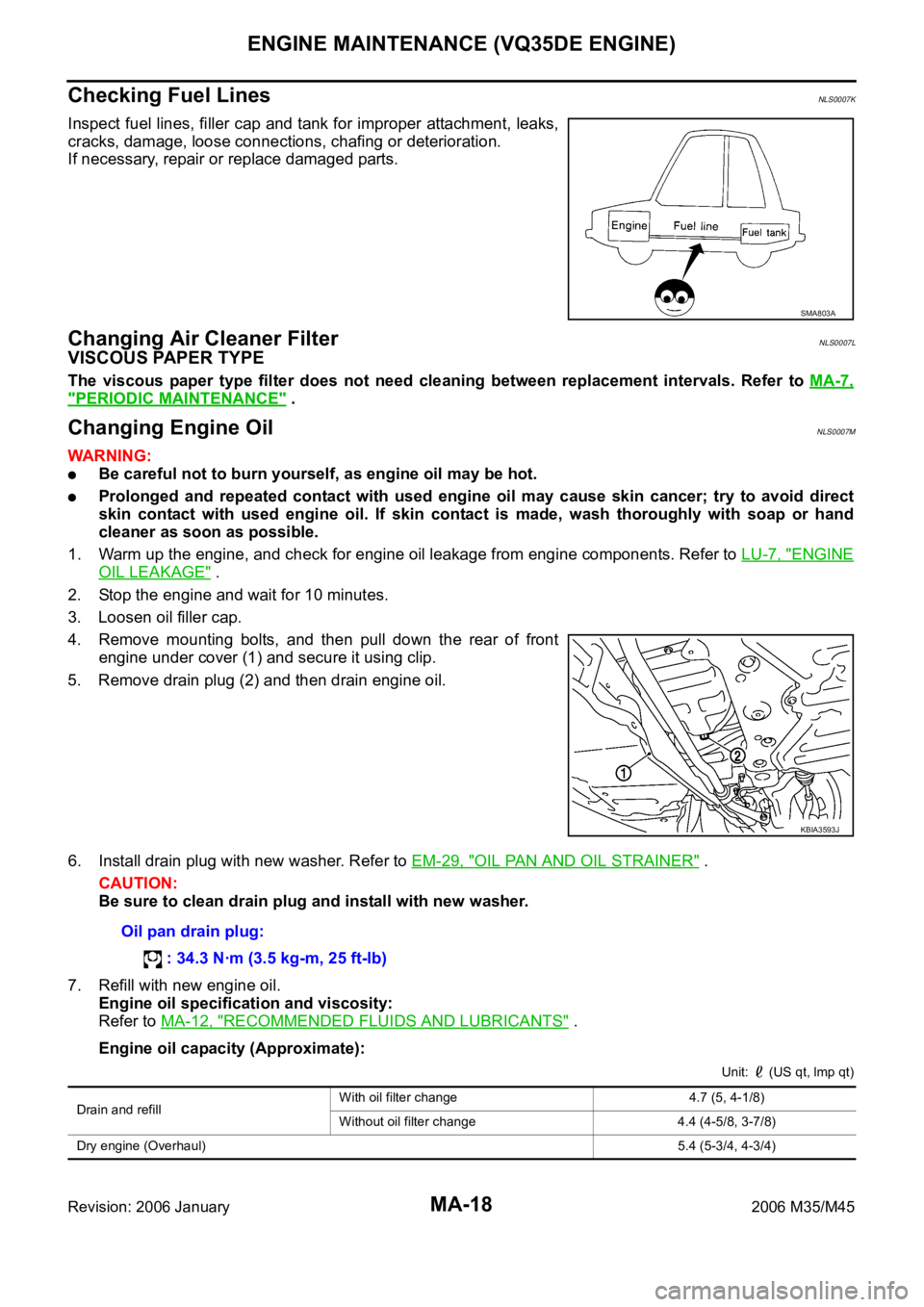
4. Remove mounting bolts, and then pull down the rear of front
engine under cover (1) and secure it using clip.
5. Remove drain plug (2) and then drain engine oil.
6. Install drain plug with new washer. Refer to EM-29, "
OIL PAN AND OIL STRAINER" .
CAUTION:
Be sure to clean drain plug and install with new washer.
7. Refill with new engine oil.
Engine oil specification and viscosity:
Refer to MA-12, "
RECOMMENDED FLUIDS AND LUBRICANTS" .
Engine oil capacity (Approximate):
Unit: (US qt, lmp qt)
SMA803A
KBIA3593J
Oil pan drain plug:
: 34.3 Nꞏm (3.5 kg-m, 25 ft-lb)
Drain and refill With oil filter change 4.7 (5, 4-1/8)
Without oil filter change 4.4 (4-5/8, 3-7/8)
Dry engine (Overhaul)5.4 (5-3/4, 4-3/4)
Page 4802 of 5621
ENGINE MAINTENANCE (VK45DE ENGINE)
MA-25
C
D
E
F
G
H
I
J
K
MA
B
MA
Revision: 2006 January2006 M35/M45
4. Run engine and warm it up to normal operating temperature.
5. Rev engine two or three times under no-load.
6. Stop engine and wait until it cools down.
7. Drain water from the system. Refer to CO-40, "
DRAINING ENGINE COOLANT" .
8. Repeat steps 1 through 7 until clear water begins to drain from radiator.
Checking Fuel LinesNLS0007T
Inspect fuel lines, fuel filler cap and fuel tank for improper attach-
ment, leaks, cracks, damage, loose connections, chafing or deterio-
ration.
If necessary, repair or replace damaged parts.
Changing Air Cleaner FilterNLS0007U
VISCOUS PAPER TYPE
The viscous paper type filter does not need cleaning between replacement intervals. Refer to MA-7,
"PERIODIC MAINTENANCE" .
Changing Engine OilNLS0007V
WAR NING :
Be careful not to burn yourself, as engine oil may be hot.
Prolonged and repeated contact with used engine oil may cause skin cancer; try to avoid direct
skin contact with used engine oil. If skin contact is made, wash thoroughly with soap or hand
cleaner as soon as possible.
1. Warm up engine, put vehicle horizontally and check for engine oil leakage from engine components. Refer
to LU-26, "
ENGINE OIL LEAKAGE" .
2. Stop engine and wait for 15 minutes.
3. Loosen oil filler cap.
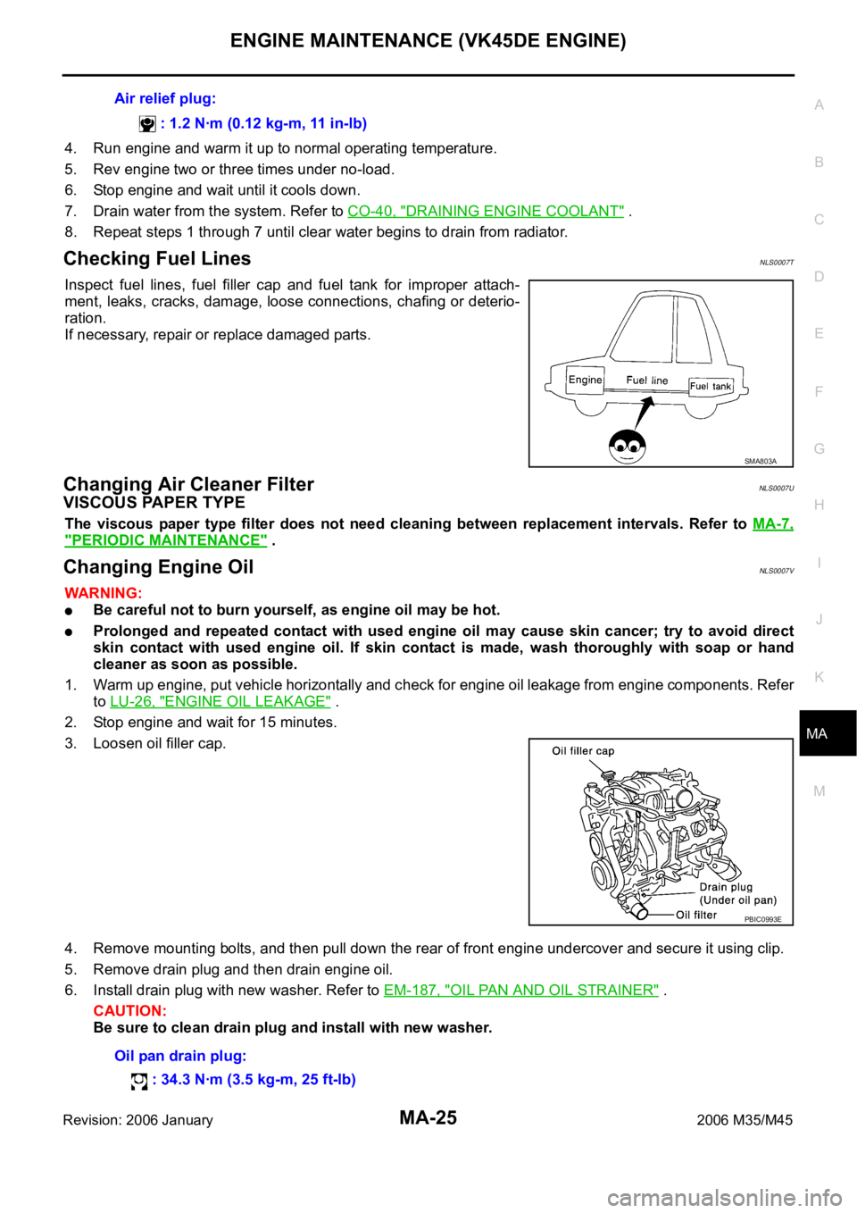
4. Remove mounting bolts, and then pull down the rear of front engine undercover and secure it using clip.
5. Remove drain plug and then drain engine oil.
6. Install drain plug with new washer. Refer to EM-187, "
OIL PAN AND OIL STRAINER" .
CAUTION:
Be sure to clean drain plug and install with new washer.Air relief plug:
: 1.2 Nꞏm (0.12 kg-m, 11 in-lb)
SMA803A
PBIC0993E
Oil pan drain plug:
: 34.3 Nꞏm (3.5 kg-m, 25 ft-lb)
Page 4808 of 5621
CHASSIS AND BODY MAINTENANCE
MA-31
C
D
E
F
G
H
I
J
K
MA
B
MA
Revision: 2006 January2006 M35/M45
Changing A/T FluidNLS00081
1. Warm up ATF.
2. Stop engine.
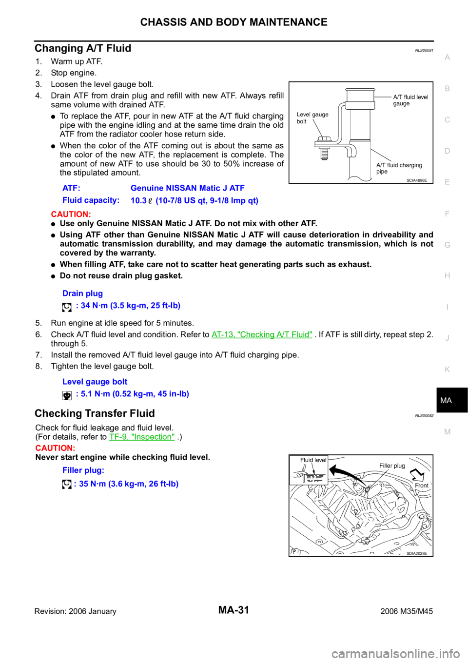
3. Loosen the level gauge bolt.
4. Drain ATF from drain plug and refill with new ATF. Always refill
same volume with drained ATF.
To replace the ATF, pour in new ATF at the A/T fluid charging
pipe with the engine idling and at the same time drain the old
ATF from the radiator cooler hose return side.
When the color of the ATF coming out is about the same as
the color of the new ATF, the replacement is complete. The
amount of new ATF to use should be 30 to 50% increase of
the stipulated amount.
CAUTION:
Use only Genuine NISSAN Matic J ATF. Do not mix with other ATF.
Using ATF other than Genuine NISSAN Matic J ATF will cause deterioration in driveability and
automatic transmission durability, and may damage the automatic transmission, which is not
covered by the warranty.
When filling ATF, take care not to scatter heat generating parts such as exhaust.
Do not reuse drain plug gasket.
5. Run engine at idle speed for 5 minutes.
6. Check A/T fluid level and condition. Refer to AT- 1 3 , "
Checking A/T Fluid" . If ATF is still dirty, repeat step 2.
through 5.
7. Install the removed A/T fluid level gauge into A/T fluid charging pipe.
8. Tighten the level gauge bolt.
Checking Transfer FluidNLS00082
Check for fluid leakage and fluid level.
(For details, refer to TF-9, "
Inspection" .)
CAUTION:
Never start engine while checking fluid level.ATF: Genuine NISSAN Matic J ATF
Fluid capacity:
10.3 (10-7/8 US qt, 9-1/8 lmp qt)
Drain plug
: 34 Nꞏm (3.5 kg-m, 25 ft-lb)
Level gauge bolt
: 5.1 Nꞏm (0.52 kg-m, 45 in-lb)
SCIA4896E
Filler plug:
: 35 Nꞏm (3.6 kg-m, 26 ft-lb)
SDIA2028E
Page 4971 of 5621
PS-18
POWER STEERING GEAR
Revision: 2006 January2006 M35/M45
POWER STEERING GEARPFP:49001
Removal and InstallationNGS000DC
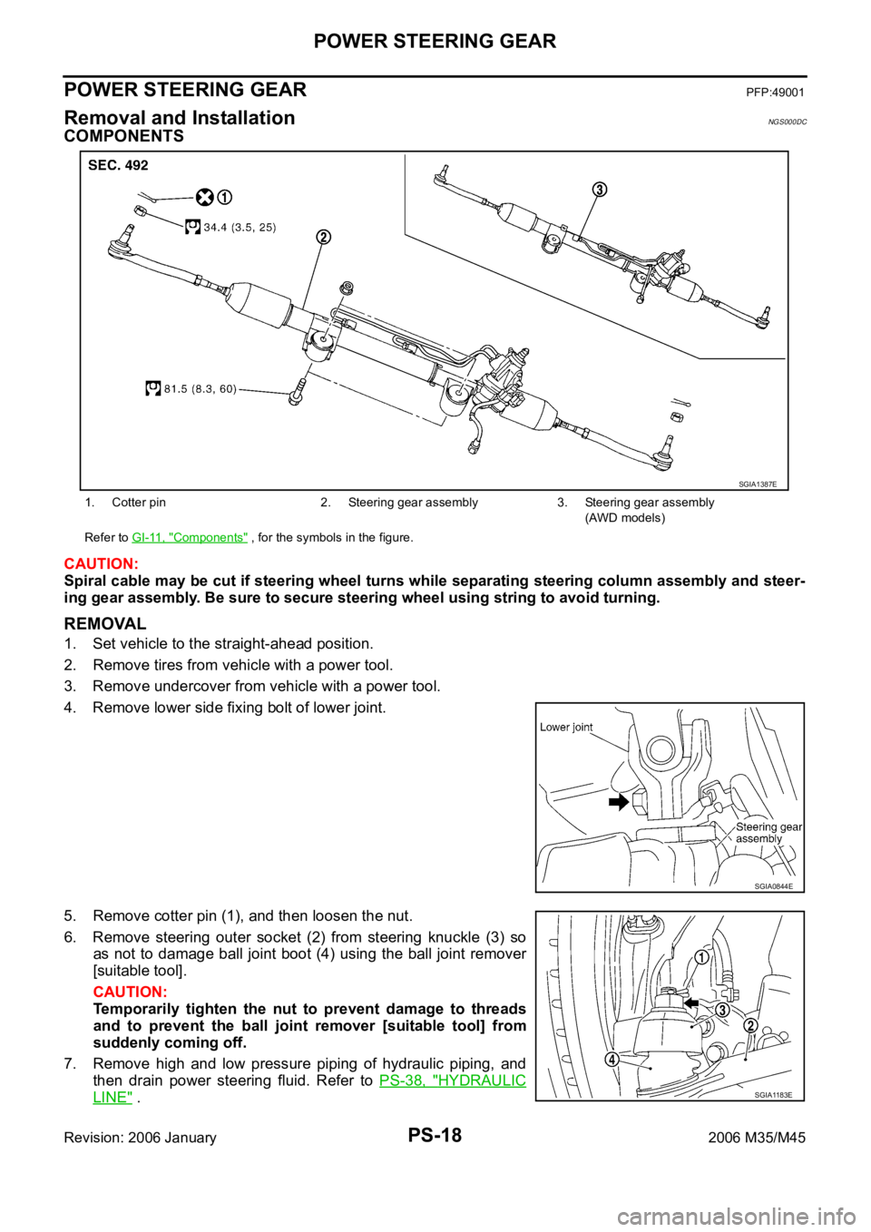
COMPONENTS
CAUTION:
Spiral cable may be cut if steering wheel turns while separating steering column assembly and steer-
ing gear assembly. Be sure to secure steering wheel using string to avoid turning.
REMOVAL
1. Set vehicle to the straight-ahead position.
2. Remove tires from vehicle with a power tool.
3. Remove undercover from vehicle with a power tool.
4. Remove lower side fixing bolt of lower joint.
5. Remove cotter pin (1), and then loosen the nut.
6. Remove steering outer socket (2) from steering knuckle (3) so
as not to damage ball joint boot (4) using the ball joint remover
[suitable tool].
CAUTION:
Temporarily tighten the nut to prevent damage to threads
and to prevent the ball joint remover [suitable tool] from
suddenly coming off.
7. Remove high and low pressure piping of hydraulic piping, and
then drain power steering fluid. Refer to PS-38, "
HYDRAULIC
LINE" .
1. Cotter pin 2. Steering gear assembly 3. Steering gear assembly
(AWD models)
Refer to GI-11, "
Components" , for the symbols in the figure.
SGIA1387E
SGIA0844E
SGIA1183E
Page 4982 of 5621
POWER STEERING OIL PUMP
PS-29
C
D
E
F
H
I
J
K
L
MA
B
PS
Revision: 2006 January2006 M35/M45
POWER STEERING OIL PUMPPFP:49110
On-Vehicle Inspection and ServiceNGS000DE
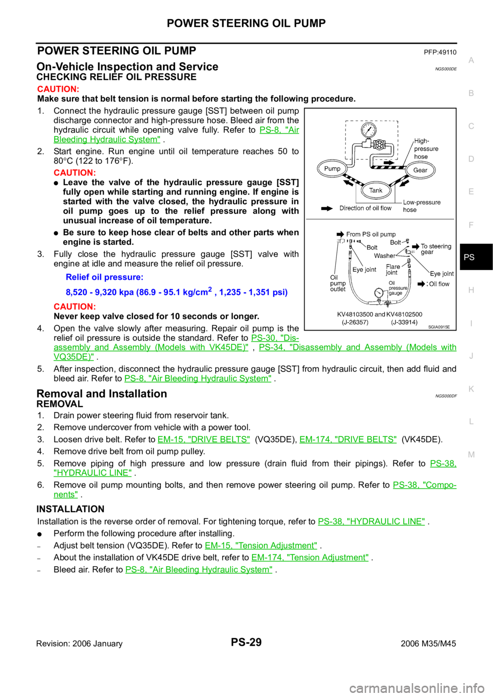
CHECKING RELIEF OIL PRESSURE
CAUTION:
Make sure that belt tension is normal before starting the following procedure.
1. Connect the hydraulic pressure gauge [SST] between oil pump
discharge connector and high-pressure hose. Bleed air from the
hydraulic circuit while opening valve fully. Refer to PS-8, "
Air
Bleeding Hydraulic System" .
2. Start engine. Run engine until oil temperature reaches 50 to
80
C (122 to 176F).
CAUTION:
Leave the valve of the hydraulic pressure gauge [SST]
fully open while starting and running engine. If engine is
started with the valve closed, the hydraulic pressure in
oil pump goes up to the relief pressure along with
unusual increase of oil temperature.
Be sure to keep hose clear of belts and other parts when
engine is started.
3. Fully close the hydraulic pressure gauge [SST] valve with
engine at idle and measure the relief oil pressure.
CAUTION:
Never keep valve closed for 10 seconds or longer.
4. Open the valve slowly after measuring. Repair oil pump is the
relief oil pressure is outside the standard. Refer to PS-30, "
Dis-
assembly and Assembly (Models with VK45DE)" , PS-34, "Disassembly and Assembly (Models with
VQ35DE)" .
5. After inspection, disconnect the hydraulic pressure gauge [SST] from hydraulic circuit, then add fluid and
bleed air. Refer to PS-8, "
Air Bleeding Hydraulic System" .
Removal and InstallationNGS000DF
REMOVAL
1. Drain power steering fluid from reservoir tank.
2. Remove undercover from vehicle with a power tool.
3. Loosen drive belt. Refer to EM-15, "
DRIVE BELTS" (VQ35DE), EM-174, "DRIVE BELTS" (VK45DE).
4. Remove drive belt from oil pump pulley.
5. Remove piping of high pressure and low pressure (drain fluid from their pipings). Refer to PS-38,
"HYDRAULIC LINE" .
6. Remove oil pump mounting bolts, and then remove power steering oil pump. Refer to PS-38, "
Compo-
nents" .
INSTALLATION
Installation is the reverse order of removal. For tightening torque, refer to PS-38, "HYDRAULIC LINE" .
Perform the following procedure after installing.
–Adjust belt tension (VQ35DE). Refer to EM-15, "Tension Adjustment" .
–About the installation of VK45DE drive belt, refer to EM-174, "Tension Adjustment" .
–Bleed air. Refer to PS-8, "Air Bleeding Hydraulic System" . Relief oil pressure:
8,520 - 9,320 kpa (86.9 - 95.1 kg/cm
2 , 1,235 - 1,351 psi)
SGIA0915E
Page 5040 of 5621
SUNROOF
RF-27
C
D
E
F
G
H
J
K
L
MA
B
RF
Revision: 2006 January2006 M35/M45
SUNROOF UNIT
Removal
CAUTION:
Always work with a helper.
When taking sunroof unit out, use clothes to protect the seats and trim from damage.
After installing the sunroof unit and glass lid, be sure to carry out the leak test and check that
there is no malfunction.
1. Remove the headlining. Refer to EI-52, "
HEADLINING" .
2. Disconnect drain hoses.
3. Tilt up glass lid, and then remove glass lid.
4. Remove sunroof motor assembly mounting screws. Disconnect connector from sunroof motor assembly
and then remove sunroof motor assembly.
CAUTION:
Before removing sunroof motor, make sure that sunroof lid is fully closed.
After removing sunroof motor, do not attempt to rotate sunroof motor assembly as a single unit.
5. Remove nuts from the front end and side rail.
6. Remove front sunroof bracket bolts.
7. Remove rear sunroof bracket bolts, and then remove sunroof unit assembly from roof panel.
8. Remove sunroof unit assembly through the passenger compartment while being careful not to damage
the seats and trim.
Installation
1. Temporarily tighten the mounting bolts to the rear sunroof brackets (RH/LH).
2. Bring sunroof unit into passenger compartment, and then place the rear end of the rail onto the rear sun-
roof brackets.
3. Temporarily tighten the mounting nuts to the front end of sunroof unit assembly.
4. Tighten the installation points diagonally excluding the installation point of the sunroof bracket around the
roof opening.
5. Tighten the front sunroof bracket bolts of the vehicle side, and then tighten the bolt of the rail side.
6. Tighten the rear sunroof bracket bolts of the vehicle side, and then tighten the bolt of the rail side.
7. Tighten the mounting nuts to the front end and side rail.
8. Move the sunroof motor assembly laterally by little by little so that the gear is completely engaged into the
wire on the sunroof unit assembly and mounting surface becomes parallel. Then secure the sunroof motor
assembly with screws.
CAUTION:
Before installing the sunroof motor assembly, be sure to the place the link and wire assembly in
the symmetrical and fully closed position.
9. Install glass lid.
NOTE:
After installation, carry out fitting adjustment.
10. Connect drain hoses.
11. Install headlining. Refer to EI-52, "
HEADLINING" .
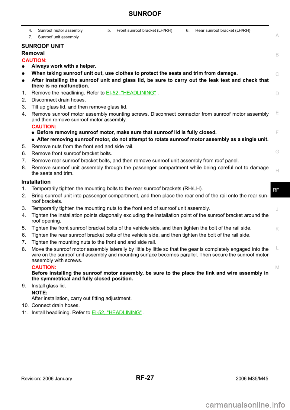
4. Sunroof motor assembly 5. Front sunroof bracket (LH/RH) 6. Rear sunroof bracket (LH/RH)
7. Sunroof unit assembly
Page 5061 of 5621
RFD-18
REAR FINAL DRIVE ASSEMBLY
Revision: 2006 January2006 M35/M45
Disassembly and AssemblyNDS000F8
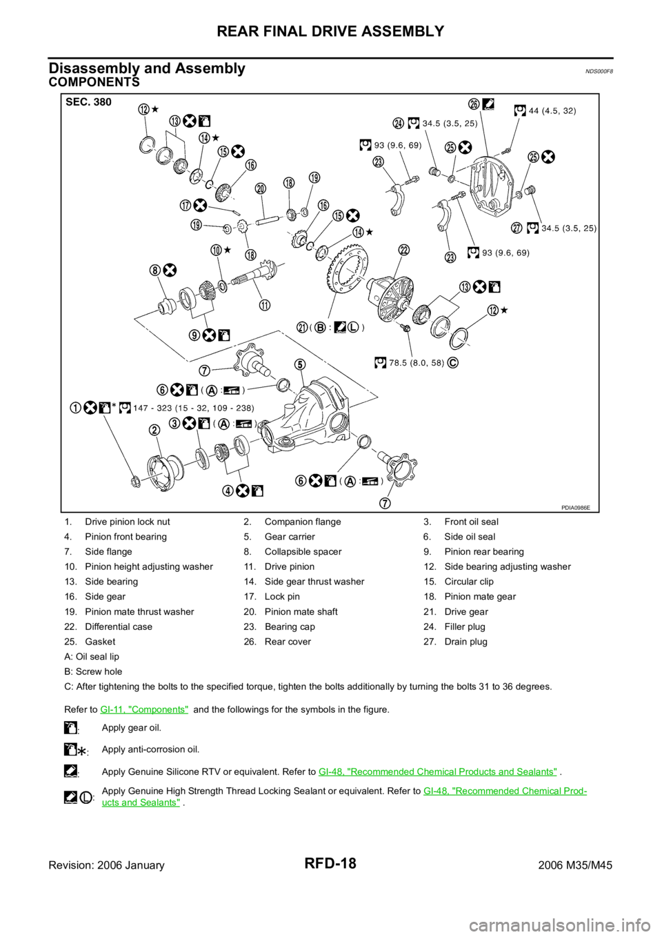
COMPONENTS
1. Drive pinion lock nut 2. Companion flange 3. Front oil seal
4. Pinion front bearing 5. Gear carrier 6. Side oil seal
7. Side flange 8. Collapsible spacer 9. Pinion rear bearing
10. Pinion height adjusting washer 11. Drive pinion 12. Side bearing adjusting washer
13. Side bearing 14. Side gear thrust washer 15. Circular clip
16. Side gear 17. Lock pin 18. Pinion mate gear
19. Pinion mate thrust washer 20. Pinion mate shaft 21. Drive gear
22. Differential case 23. Bearing cap 24. Filler plug
25. Gasket 26. Rear cover 27. Drain plug
A: Oil seal lip
B: Screw hole
C: After tightening the bolts to the specified torque, tighten the bolts additionally by turning the bolts 31 to 36 degrees.
Refer to GI-11, "
Components" and the followings for the symbols in the figure.
:Apply gear oil.
:Apply anti-corrosion oil.
:Apply Genuine Silicone RTV or equivalent. Refer to GI-48, "
Recommended Chemical Products and Sealants" .
:Apply Genuine High Strength Thread Locking Sealant or equivalent. Refer to GI-48, "
Recommended Chemical Prod-
ucts and Sealants" .
PDIA0986E