2006 INFINITI M35 fuel filter
[x] Cancel search: fuel filterPage 3422 of 5621
FUEL LEVEL SENSOR UNIT, FUEL FILTER AND FUEL PUMP ASSEMBLY
FL-9
C
D
E
F
G
H
I
J
K
L
MA
FL
Revision: 2006 January2006 M35/M45
ASSEMBLY
1. Check for damage of fuel level sensor unit installation position on the side of fuel filter and fuel pump
assembly.
2. Slide fuel level sensor unit until it aligns to installation groove, then insert it until it stops.
After inserting, apply force in reverse direction (removal direction) to ensure it cannot be pulled out.
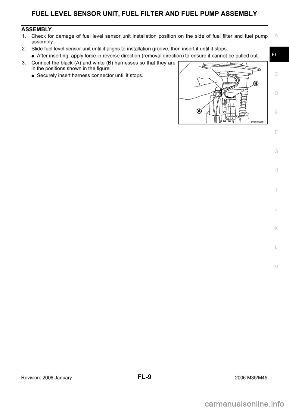
3. Connect the black (A) and white (B) harnesses so that they are
in the positions shown in the figure.
Securely insert harness connector until it stops.
PBIC3387E
Page 3423 of 5621
FL-10
FUEL TANK
Revision: 2006 January2006 M35/M45
FUEL TANKPFP:17202
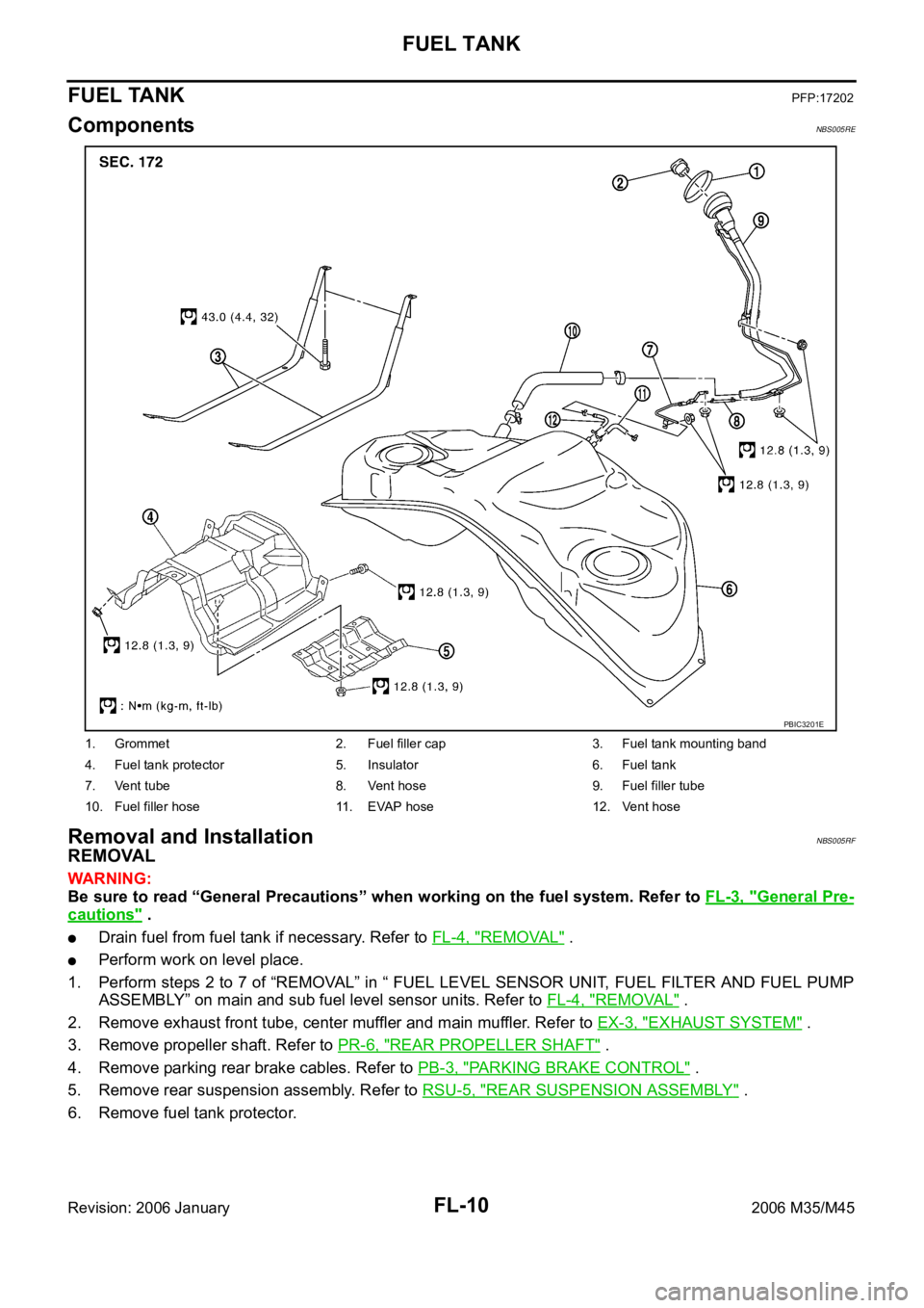
ComponentsNBS005RE
Removal and InstallationNBS005RF
REMOVAL
WAR NING :
Be sure to read “General Precautions” when working on the fuel system. Refer to FL-3, "
General Pre-
cautions" .
Drain fuel from fuel tank if necessary. Refer to FL-4, "REMOVAL" .
Perform work on level place.
1. Perform steps 2 to 7 of “REMOVAL” in “ FUEL LEVEL SENSOR UNIT, FUEL FILTER AND FUEL PUMP
ASSEMBLY” on main and sub fuel level sensor units. Refer to FL-4, "
REMOVAL" .
2. Remove exhaust front tube, center muffler and main muffler. Refer to EX-3, "
EXHAUST SYSTEM" .
3. Remove propeller shaft. Refer to PR-6, "
REAR PROPELLER SHAFT" .
4. Remove parking rear brake cables. Refer to PB-3, "
PARKING BRAKE CONTROL" .
5. Remove rear suspension assembly. Refer to RSU-5, "
REAR SUSPENSION ASSEMBLY" .
6. Remove fuel tank protector.
1. Grommet 2. Fuel filler cap 3. Fuel tank mounting band
4. Fuel tank protector 5. Insulator 6. Fuel tank
7. Vent tube 8. Vent hose 9. Fuel filler tube
10. Fuel filler hose 11. EVAP hose 12. Vent hose
PBIC3201E
Page 3643 of 5621
IDX-2
ALPHABETICAL INDEX
A
A/C air flow ...................................................... ATC-37
A/C component layout ..................................... ATC-25
A/C compressor mounting ........... ATC-155, ATC-158,
ATC-159
, ATC-160, ATC-162, ATC-164, ATC-165,
ATC-167
, ATC-168, ATC-169
A/C compressor precaution ............................. ATC-12
A/C compressor special service tool ................ ATC-16
A/C control operation (auto A/C) ...................... ATC-33
A/C diagnostic work flow (auto A/C) .............. ATC-111
A/C evaporator ............................................... ATC-168
A/C HFC134a (R134a) system precaution ........ ATC-6
A/C HFC134a (R134a) system service procedure .......
ATC-151
A/C HFC134a (R134a) system service tools ... ATC-17
A/C HFC134a system service equipment precaution ...
ATC-13
A/C lubricant (R134a) ...................................... ATC-26
A/C lubrication oil ........................................... ATC-174
A/C operational check ...................................... ATC-64
A/C self-diagnoses (auto A/C) ........ ATC-55, ATC-111
A/C service data specification ........................ ATC-174
A/C system description (auto A/C) ................... ATC-29
A/C trouble diagnoses (auto A/C) .................... ATC-40
A/C, A - Wiring diagram ................................... ATC-46
A/T fluid checking ...................... AT-13, AT-53, MA-29
A/T fluid cooler cleaning .................................... AT-14
A/T fluid replacement ............................. AT-12, MA-31
A/T fluid temperature sensor ........................... AT-135
A/T IND - Wiring diagram .................................... DI-57
A/T self-diagnoses ............................... AT-92, AT-103
A/T shift lock system ........................................ AT-229
A/T shift lock system - Wiring diagram ............ AT-230
A/T trouble diagnoses ........................................ AT-44
Accelerator control system ............................... ACC-3
Accelerator pedal position (APP) sensor ........ EC-626,
EC-633
, EC-647, EC-1358, EC-1365, EC-1379
Accelerator pedal released position learning .... EC-95,
EC-806
AF1B1-Wiring diagram ...... EC-249, EC-258, EC-267,
EC-277
, EC-657, EC-972, EC-981, EC-990, EC-1000,
EC-1389
AF1B2-Wiring diagram ...... EC-251, EC-260, EC-269,
EC-279
, EC-659, EC-974, EC-983, EC-992, EC-1002,
EC-1391
AF1HB1-Wiring diagram .................... EC-183, EC-905
AF1HB2-Wiring diagram .................... EC-185, EC-907
Air bag .............................................................. SRS-3
Air bag precautions ........................................... SRS-3
Air cleaner and air duct(VK45DE) ................... EM-177
Air cleaner and air duct(VQ35DE) .................... EM-17
Air cleaner filter replacement ............................ MA-25
Air cleaner filter replacement(VQ35DE) ........... MA-18
Air cleaner filter(VQ35DE) ................................ EM-18
Air conditioner cut control .................... EC-35, EC-745
Air flow meter - See Mass air flow sensor ...... EC-205,
EC-214
, EC-927, EC-936
Air fuel ratio sensor 1 ......... EC-246, EC-256, EC-265, EC-274
, EC-655, EC-969, EC-979, EC-988, EC-997,
EC-1387
Air fuel ratio sensor 1 heater ............. EC-182, EC-904
Air mix. door motor ......................... ATC-83, ATC-141
Alternator ........................................................... SC-23
Ambient sensor ............................. ATC-113, ATC-126
Angular tightening application ............................. EM-6
Angular tightening application(VK45DE) ........ EM-164
APPS1 - Wiring diagram ................. EC-628, EC-1360
APPS2 - Wiring diagram ................. EC-635, EC-1367
APPS3 - Wiring diagram ................. EC-649, EC-1381
ASC/BS - Wiring diagram ............... EC-587, EC-1313
ASC/SW - Wiring diagram .............. EC-570, EC-1296
ASCBOF - Wiring diagram .............. EC-708, EC-1450
ASCD .................................................. EC-36, EC-746
ASCD (automatic speed control device) ........... ACS-3
ASCIND - Wiring diagram ............... EC-715, EC-1457
AT indicator lamp ................................................ DI-56
Auto air conditioner - Wiring diagram ............. ATC-46
Auto amp ...................................................... ATC-125
Auto anti-dazzling inside mirror .......... GW-71, GW-72
Automatic amplifier ........... ATC-53, ATC-66, ATC-125
Automatic transmission fluid replacement ........ MA-32
AWD - Wiring diagram ....................................... TF-17
Axle ................................................................... MA-37
B
Back-up lamp ................................................... LT-246
Basic inspection .................................. EC-77, EC-788
Battery ................................................................. SC-4
Battery current sensor ....... EC-537, EC-543, EC-549,
EC-555
, EC-1263, EC-1269, EC-1275, EC-1281
Battery/Starting/Charging System Tester .......... SC-28
Battery/Starting/Charging System Tester(Battery) SC-7
Battery/Starting/Charging System Tester(Starting
system) .............................................................. SC-13
BCM (Body control module) .............................. BCS-3
Block heater(VK45DE) .................................... EM-249
Block heater(VQ35DE) ................................... EM-123
Blower motor ................................... ATC-89, ATC-132
Blower unit .................................................... ATC-130
Brake fluid level ................................................ MA-35
Brake hydraulic line ........................................... BR-12
Brake inspection ............................................... MA-36
Brake lines and cables inspection .................... MA-35
Brake pedal .......................................................... BR-6
Brake switch ................................... EC-598, EC-1329
BRK/SW - Wiring diagram .............. EC-600, EC-1331
Bulb specifications ........................................... LT-315
Bumper, front ...................................................... EI-11
Bumper, rear ....................................................... EI-14
C
Camshaft inspection(VK45DE) ....................... EM-216
Camshaft inspection(VQ35DE) ......................... EM-86
Camshaft position sensor (PHASE) EC-383, EC-1106
Camshaft(VK45DE) ........................................ EM-215
Page 3645 of 5621
IDX-4
ALPHABETICAL INDEX
Electronic ignition (EI) system ............. EC-33, EC-743
Engine control module (ECM) .......... EC-496, EC-1215
Engine control system diagram ........... EC-30, EC-740
Engine coolant temperature sensor (ECTS) ... EC-226,
EC-238
, EC-948, EC-961
Engine coolant(VK45DE) .................................. CO-40
Engine coolant(VQ35DE) ................................. CO-11
Engine oil filter replacement ............................. MA-26
Engine oil filter replacement(VQ35DE) ............. MA-19
Engine oil precautions .......................................... GI-8
Engine oil replacement(VQ35DE) ..................... MA-18
Engine oil(VK45DE) ........................................... LU-26
Engine oil(VQ35DE) ............................................ LU-7
Engine removal(VK45DE) ............................... EM-244
Engine removal(VQ35DE) .............................. EM-113
Engine room cover ............................................ EM-14
Engine room cover(VK45DE) ......................... EM-173
ETC1 - Wiring diagram .................... EC-614, EC-1345
ETC2 - Wiring diagram .................... EC-609, EC-1340
ETC3 - Wiring diagram .................... EC-620, EC-1352
EVAP canister ...................................... EC-42, EC-752
EVAP canister purge volume control solenoid valve ....
EC-412
, EC-420, EC-1132, EC-1140
EVAP canister vent control valve ...... EC-427, EC-434,
EC-1147
, EC-1154
EVAP control system (small leak) diagnosis .. EC-403,
EC-466
, EC-1124, EC-1185
EVAP control system pressure sensor ........... EC-440,
EC-443
, EC-450, EC-1160, EC-1163, EC-1170
EVAP control system purge flow monitoring diagnosis
EC-398
, EC-1119
EVAP vapor lines inspection ................. MA-21, MA-28
Evaporative emission (EVAP) system . EC-39, EC-749
Evaporator ..................................................... ATC-168
Exhaust manifold(VK45DE) ............................ EM-183
Exhaust system ................................................... EX-3
Exhaust system inspection ..................... EX-3, MA-29
Expansion valve ............................................. ATC-169
F
F/FOG - Wiring diagram ................................... LT-197
F/PUMP - Wiring diagram ................ EC-686, EC-1428
Final drive pre-inspection .................. FFD-16, RFD-19
Final drive removal and installation .. FFD-13, RFD-16
Floor trim ............................................................. EI-50
Flow charts ......................................................... GI-28
Fluid temperature sensor (A/T) ........................ AT-135
Fluorescent leak detector .............................. ATC-170
FPCM - Wiring diagram ................... EC-527, EC-1253
Freeze frame data ............................... EC-59, EC-770
Front brake solenoid valve ................. AT-151, AT-153
Front bumper ...................................................... EI-11
Front combination lamp removal and installation LT-76
Front door ............................. BL-190, BL-196, GW-63
Front passenger air bag .................................. SRS-42
Front seat belt .................................................... SB-30
Front seat belt pre-tensioner ..... SB-2, SRS-3, SRS-47
Front washer ...................................................... WW-4
Front wiper ......................................................... WW-4
FTS - Wiring diagram ....................................... AT-136
FTTS - Wiring diagram .... EC-345, EC-350, EC-1068,
EC-1073
Fuel cut control (at no load high engine speed) EC-34,
EC-744
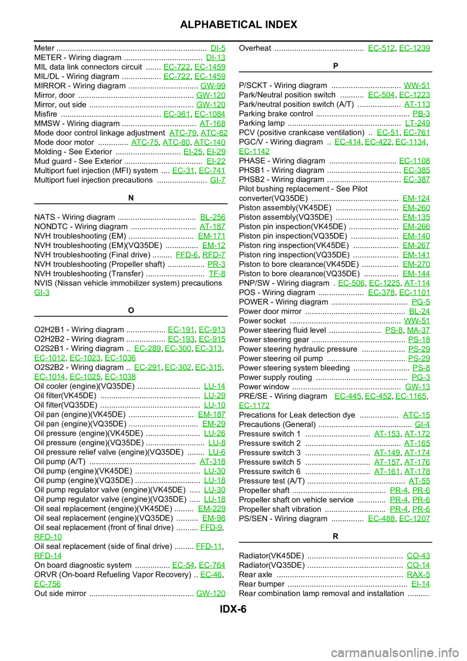
Fuel filter replacement ......................................... FL-4
Fuel gauge ............................................................ DI-5
Fuel injection system (Bank 1) ......... EC-321, EC-332,
EC-1044
, EC-1055
Fuel injection system (Bank 2) ......... EC-321, EC-332,
EC-1044
, EC-1055
Fuel injector ................................................... EC-1420
Fuel injector and fuel tube(VK45DE) .............. EM-193
Fuel injector and fuel tube(VQ35DE) ................ EM-45
Fuel level sensor EC-475, EC-477, EC-479, EC-1194,
EC-1196
, EC-1198
Fuel line inspection .................................. FL-3, MA-25
Fuel line inspection(VQ35DE) .......................... MA-18
Fuel precautions ................................................... GI-6
Fuel pressure check ........................... EC-98, EC-809
Fuel pressure release ......................... EC-98, EC-809
Fuel pump ....................................... EC-685, EC-1427
Fuel pump and gauge .......................................... FL-4
Fuel pump control module .............. EC-525, EC-1251
Fuel pump dropping resistor ........... EC-525, EC-1251
Fuel system ......................................................... FL-3
Fuel tank ............................................................ FL-10
Fuel tank temperature sensor .......... EC-343, EC-349,
EC-1066
, EC-1072
Fuel tank vacuum relief valve ............. EC-42, EC-752
FUELB1 - Wiring diagram EC-323, EC-334, EC-1046,
EC-1057
FUELB2 - Wiring diagram EC-325, EC-336, EC-1048,
EC-1059
Fuse .................................................................. PG-17
Fuse and fusible link box ................................ PG-112
Fusible link ........................................................ PG-17
G
Gauges ................................................................. DI-5
Generator ........................................................... SC-23
Generator - See Alternator ................................ SC-23
Glass ........................ GW-11, GW-61, GW-63, GW-67
Grille - See Exterior ............................................ EI-16
Ground distribution ........................................... PG-46
H
H/LAMP - Wiring diagram ....................... LT-13
, LT-48
Harness connector .......................................... PG-102
Harness layout .................................................. PG-63
Hazard warning lamp ....................................... LT-211
Headlamp removal and installation .................... LT-76
Headlining - See Roof trim .................................. EI-52
Heated oxygen sensor 2 (bank 1) .... EC-286, EC-297,
EC-310
, EC-1009, EC-1020, EC-1033
Heated oxygen sensor 2 (bank 2) .... EC-286, EC-297,
Page 3647 of 5621
IDX-6
ALPHABETICAL INDEX
Meter ..................................................................... DI-5
METER - Wiring diagram .................................... DI-13
MIL data link connectors circuit ....... EC-722, EC-1459
MIL/DL - Wiring diagram .................. EC-722, EC-1459
MIRROR - Wiring diagram ................................ GW-99
Mirror, door ..................................................... GW-120
Mirror, out side ................................................ GW-120
Misfire .............................................. EC-361, EC-1084
MMSW - Wiring diagram .................................. AT-168
Mode door control linkage adjustment ATC-79, ATC-82
Mode door motor .............. ATC-75, ATC-80, ATC-140
Molding - See Exterior .............................. EI-25, EI-29
Mud guard - See Exterior .................................... EI-22
Multiport fuel injection (MFI) system .... EC-31, EC-741
Multiport fuel injection precautions ....................... GI-7
N
NATS - Wiring diagram .................................... BL-256
NONDTC - Wiring diagram .............................. AT-187
NVH troubleshooting (EM) .............................. EM-171
NVH troubleshooting (EM)(VQ35DE) ............... EM-12
NVH troubleshooting (Final drive) ......... FFD-6, RFD-7
NVH troubleshooting (Propeller shaft) ................. PR-3
NVH troubleshooting (Transfer) ........................... TF-8
NVIS (Nissan vehicle immobilizer system) precautions
GI-3
O
O2H2B1 - Wiring diagram .................. EC-191
, EC-913
O2H2B2 - Wiring diagram .................. EC-193, EC-915
O2S2B1 - Wiring diagram .. EC-289, EC-300, EC-313,
EC-1012
, EC-1023, EC-1036
O2S2B2 - Wiring diagram .. EC-291, EC-302, EC-315,
EC-1014
, EC-1025, EC-1038
Oil cooler (engine)(VQ35DE) ............................. LU-14
Oil filter(VK45DE) .............................................. LU-29
Oil filter(VQ35DE) .............................................. LU-10
Oil pan (engine)(VK45DE) .............................. EM-187
Oil pan (engine)(VQ35DE) ................................ EM-29
Oil pressure (engine)(VK45DE) ......................... LU-26
Oil pressure (engine)(VQ35DE) ........................... LU-8
Oil pressure relief valve (engine)(VQ35DE) ........ LU-6
Oil pump (A/T) ................................................. AT-318
Oil pump (engine)(VK45DE) .............................. LU-30
Oil pump (engine)(VQ35DE) .............................. LU-18
Oil pump regulator valve (engine)(VK45DE) ..... LU-30
Oil pump regulator valve (engine)(VQ35DE) ..... LU-18
Oil seal replacement (engine)(VK45DE) ......... EM-229
Oil seal replacement (engine)(VQ35DE) .......... EM-98
Oil seal replacement (front of final drive) .......... FFD-9,
RFD-10
Oil seal replacement (side of final drive) ......... FFD-11,
RFD-14
On board diagnostic system ................ EC-54, EC-764
ORVR (On-board Refueling Vapor Recovery) .. EC-46,
EC-756
Out side mirror ................................................ GW-120
Overheat ......................................... EC-512, EC-1239
P
P/SCKT - Wiring diagram ................................ WW-51
Park/Neutral position switch ........... EC-504, EC-1223
Park/neutral position switch (A/T) .................... AT-113
Parking brake control ........................................... PB-3
Parking lamp .................................................... LT-249
PCV (positive crankcase ventilation) .. EC-51, EC-761
PGC/V - Wiring diagram .. EC-414, EC-422, EC-1134,
EC-1142
PHASE - Wiring diagram ............................... EC-1108
PHSB1 - Wiring diagram .................................. EC-385
PHSB2 - Wiring diagram .................................. EC-387
Pilot bushing replacement - See Pilot
converter(VQ35DE) ........................................ EM-124
Piston assembly(VK45DE) ............................. EM-260
Piston assembly(VQ35DE) ............................. EM-135
Piston pin inspection(VK45DE) ....................... EM-266
Piston pin inspection(VQ35DE) ...................... EM-140
Piston ring inspection(VK45DE) ..................... EM-267
Piston ring inspection(VQ35DE) ..................... EM-141
Piston to bore clearance(VK45DE) ................. EM-270
Piston to bore clearance(VQ35DE) ................ EM-144
PNP/SW - Wiring diagram . EC-506, EC-1225, AT-114
POS - Wiring diagram ..................... EC-378, EC-1101
POWER - Wiring diagram ................................... PG-5
Power door mirror .............................................. BL-24
Power socket ................................................... WW-51
Power steering fluid level ........................ PS-8, MA-37
Power steering gear ........................................... PS-18
Power steering hydraulic pressure .................... PS-29
Power steering oil pump .................................... PS-29
Power steering system bleeding .......................... PS-8
Power supply routing .......................................... PG-3
Power window .................................................. GW-13
PRE/SE - Wiring diagram EC-445, EC-452, EC-1165,
EC-1172
Precations for Leak detection dye .................. ATC-15
Precautions (General) ........................................... GI-4
Pressure switch 1 .............................. AT-153, AT-172
Pressure switch 2 ............................................ AT-165
Pressure switch 3 .............................. AT-149, AT-174
Pressure switch 5 .............................. AT-157, AT-176
Pressure switch 6 .............................. AT-161, AT-178
Pressure test (A/T) ............................................. AT-55
Propeller shaft ........................................... PR-4, PR-6
Propeller shaft on vehicle service ............. PR-4, PR-6
Propeller shaft vibration ............................ PR-4, PR-6
PS/SEN - Wiring diagram ............... EC-488, EC-1207
R
Radiator(VK45DE) ............................................ CO-43
Radiator(VQ35DE) ............................................ CO-14
Rear axle .......................................................... RAX-5
Rear bumper ....................................................... EI-14
Rear combination lamp removal and installation ..........
Page 4778 of 5621
MA-1
MAINTENANCE
L MAINTENANCE
CONTENTS
C
D
E
F
G
H
I
J
K
M
SECTION MA
A
B
MA
Revision: 2006 January2006 M35/M45
MAINTENANCE
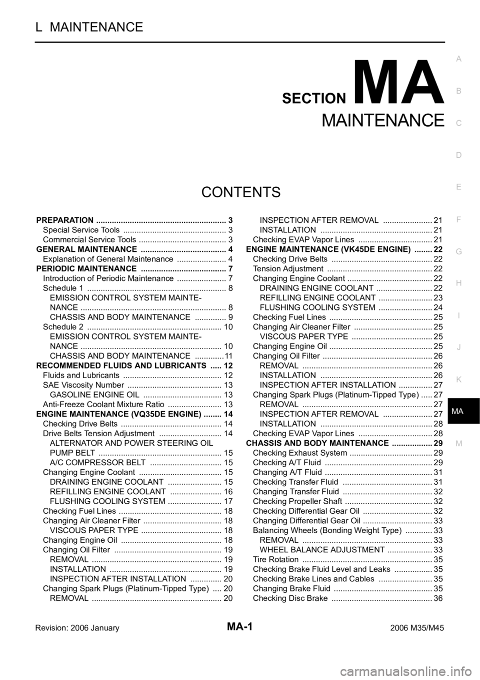
PREPARATION ........................................................... 3
Special Service Tools ............................................... 3
Commercial Service Tools ........................................ 3
GENERAL MAINTENANCE ....................................... 4
Explanation of General Maintenance ....................... 4
PERIODIC MAINTENANCE ....................................... 7
Introduction of Periodic Maintenance ....................... 7
Schedule 1 ............................................................... 8
EMISSION CONTROL SYSTEM MAINTE-
NANCE .................................................................. 8
CHASSIS AND BODY MAINTENANCE ............... 9
Schedule 2 ............................................................. 10
EMISSION CONTROL SYSTEM MAINTE-
NANCE ................................................................ 10
CHASSIS AND BODY MAINTENANCE .............. 11
RECOMMENDED FLUIDS AND LUBRICANTS ...... 12
Fluids and Lubricants ............................................. 12
SAE Viscosity Number ........................................... 13
GASOLINE ENGINE OIL .................................... 13
Anti-Freeze Coolant Mixture Ratio ......................... 13
ENGINE MAINTENANCE (VQ35DE ENGINE) ......... 14
Checking Drive Belts .............................................. 14
Drive Belts Tension Adjustment ............................. 14
ALTERNATOR AND POWER STEERING OIL
PUMP BELT ........................................................ 15
A/C COMPRESSOR BELT ................................. 15
Changing Engine Coolant ...................................... 15
DRAINING ENGINE COOLANT ......................... 15
REFILLING ENGINE COOLANT ........................ 16
FLUSHING COOLING SYSTEM ......................... 17
Checking Fuel Lines ............................................ ... 18
Changing Air Cleaner Filter .................................... 18
VISCOUS PAPER TYPE ..................................... 18
Changing Engine Oil .............................................. 18
Changing Oil Filter ................................................. 19
REMOVAL ........................................................
... 19
INSTALLATION ................................................... 19
INSPECTION AFTER INSTALLATION ............... 20
Changing Spark Plugs (Platinum-Tipped Type) ..... 20
REMOVAL ........................................................
... 20INSPECTION AFTER REMOVAL ....................... 21
INSTALLATION ................................................... 21
Checking EVAP Vapor Lines .................................. 21
ENGINE MAINTENANCE (VK45DE ENGINE) ......... 22
Checking Drive Belts .............................................. 22
Tension Adjustment .............................................
... 22
Changing Engine Coolant ....................................... 22
DRAINING ENGINE COOLANT .......................... 22
REFILLING ENGINE COOLANT ......................... 23
FLUSHING COOLING SYSTEM ......................... 24
Checking Fuel Lines ............................................ ... 25
Changing Air Cleaner Filter .................................... 25
VISCOUS PAPER TYPE ..................................... 25
Changing Engine Oil ............................................
... 25
Changing Oil Filter .................................................. 26
REMOVAL ........................................................
... 26
INSTALLATION ................................................... 26
INSPECTION AFTER INSTALLATION ................ 27
Changing Spark Plugs (Platinum-Tipped Type) ...... 27
REMOVAL ........................................................
... 27
INSPECTION AFTER REMOVAL ....................... 27
INSTALLATION ................................................... 28
Checking EVAP Vapor Lines .................................. 28
CHASSIS AND BODY MAINTENANCE ................... 29
Checking Exhaust System ...................................... 29
Checking A/T Fluid ................................................. 29
Changing A/T Fluid ................................................. 31
Checking Transfer Fluid ......................................... 31
Changing Transfer Fluid ......................................... 32
Checking Propeller Shaft ........................................ 32
Checking Differential Gear Oil ................................ 32
Changing Differential Gear Oil ................................ 33
Balancing Wheels (Bonding Weight Type) ............. 33
REMOVAL ........................................................
... 33
WHEEL BALANCE ADJUSTMENT ..................... 33
Tire Rotation ........................................................... 35
Checking Brake Fluid Level and Leaks .................. 35
Checking Brake Lines and Cables ......................... 35
Changing Brake Fluid ............................................. 35
Checking Disc Brake .............................................. 36
Page 4785 of 5621
![INFINITI M35 2006 Factory Service Manual MA-8
PERIODIC MAINTENANCE
Revision: 2006 January2006 M35/M45
Schedule 1NLS0007C
EMISSION CONTROL SYSTEM MAINTENANCE
Abbreviations: R = Replace. I = Inspect. Correct or replace if necessary. [ ]: At th INFINITI M35 2006 Factory Service Manual MA-8
PERIODIC MAINTENANCE
Revision: 2006 January2006 M35/M45
Schedule 1NLS0007C
EMISSION CONTROL SYSTEM MAINTENANCE
Abbreviations: R = Replace. I = Inspect. Correct or replace if necessary. [ ]: At th](/manual-img/42/57023/w960_57023-4784.png)
MA-8
PERIODIC MAINTENANCE
Revision: 2006 January2006 M35/M45
Schedule 1NLS0007C
EMISSION CONTROL SYSTEM MAINTENANCE
Abbreviations: R = Replace. I = Inspect. Correct or replace if necessary. [ ]: At the mileage intervals only
MAINTENANCE OPERATIONMAINTENANCE INTERVAL
Reference
Section -
Page or -
Content Title Perform at number of miles,
kilometers or months, which-
ever comes first.Miles x 1,000
(km x 1,000)
Months3.75
(6)
37.50
(12)
611 . 2 5
(18)
915
(24)
1218.75
(30)
1522.5
(36)
1826.25
(42)
2130
(48)
24
Drive belts NOTE (1)MA-14
,
MA-22
Air cleaner filter NOTE (2) [R]MA-18,
MA-25
EVAP vapor linesI*MA-21,
MA-28
Fuel linesI*MA-18,
MA-25
Fuel filter NOTE (3)—
Engine coolant NOTE (4)MA-15
,
MA-22
Engine oil R R RRRRR RMA-18,
MA-25
Engine oil filter [Use part No.
15208 31U00 (for VK45DE),
15208 65F00 (for VQ35DE)
or equivalent.]R R RRRRR RMA-19
,
MA-26
Spark plugs (PLATINUM-
TIPPED type)Replace every 105,000 miles (169,000 km).MA-20,
MA-27
Intake & exhaust valve clear-
ance*NOTE (5)EM-93, "Valve Clear-
ance", EM-
222, "Va l v e
Clearance"
MAINTENANCE OPERATIONMAINTENANCE INTERVAL
Reference
Section -
Page or -
Content Title Perform at number of miles,
kilometers or months, which-
ever comes first.Miles x 1,000
(km x 1,000)
Months33.75
(54)
2737.5
(60)
3041.25
(66)
3345
(72)
3648.75
(78)
3952.5
(84)
4256.25
(90)
4560
(96)
48
Drive belts NOTE (1) I*MA-14
,
MA-22
Air cleaner filter NOTE (2) [R]MA-18,
MA-25
EVAP vapor linesI*MA-21,
MA-28
Fuel linesI*MA-18,
MA-25
Fuel filter NOTE (3)—
Engine coolant NOTE (4) R*MA-15
,
MA-22
Engine oil R R R R R R R RMA-18,
MA-25
Engine oil filter [Use part No.
15208 31U00 (for VK45DE),
15208 65F00 (for VQ35DE)
or equivalent.]R R RRRRRRMA-19
,
MA-26
Page 4787 of 5621
MA-10
PERIODIC MAINTENANCE
Revision: 2006 January2006 M35/M45
NOTE:
(1) If towing a trailer, using a camper or a car-top carrier, or driving on rough or muddy roads, change (not just inspect) fluid (A/T, trans-
fer)/oil at every 30,000 miles (48,000 km) or 24 months. Using automatic transmission fluid other than Genuine NISSAN Matic J
ATF will cause deterioration in driveability and automatic transmission durability, and may damage the automatic transmis-
sion, which is not covered by the INFINITI new vehicle limited warranty.
(2) Refer to “Tire rotation” under the “GENERAL MAINTENANCE” heading earlier in this section.
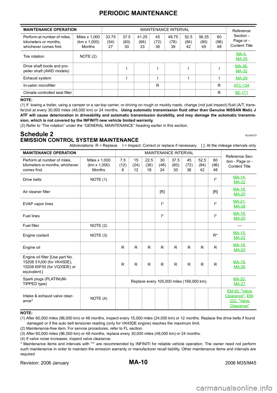
Schedule 2NLS0007D
EMISSION CONTROL SYSTEM MAINTENANCE
Abbreviations: R = Replace. I = Inspect. Correct or replace if necessary. [ ]: At the mileage intervals only
NOTE:
(1) After 60,000 miles (96,000 km) or 48 months, inspect every 15,000 miles (24,000 km) or 12 months. Replace the drive belts if found
damaged or if the auto belt tensioner reading (only for VK45DE engine) reaches the maximum limit.
(2) Maintenance-free item. For service procedures, refer to FL section.
(3) After 60,000 miles (96,000 km) or 48 months, replace every 30,000 miles (48,000 km) or 24 months.
(4) If valve noise increases, inspect valve clearance.
* Maintenance items and intervals with “*” are recommended by INFINITI for reliable vehicle operation. The owner need not perform
such maintenance in order to maintain the emission warranty or manufacturer recall liability. Other maintenance items and intervals are
required Tire rotation NOTE (2)MA-4
,
MA-35
Drive shaft boots and pro-
peller shaft (AWD models)I IIIMA-38,
MA-32
Exhaust system I I I IMA-29
In-cabin microfilter R RATC-134
Climate controlled seat filterRSE-171
MAINTENANCE OPERATIONMAINTENANCE INTERVAL
Reference
Section -
Page or -
Content Title Perform at number of miles,
kilometers or months,
whichever comes first.Miles x 1,000
(km x 1,000)
Months33.75
(54)
2737.5
(60)
3041.25
(66)
3345
(72)
3648.75
(78)
3952.5
(84)
4256.25
(90)
4560
(96)
48
MAINTENANCE OPERATIONMAINTENANCE INTERVAL
Reference Sec-
tion - Page or -
Content Title Perform at number of miles,
kilometers or months, whichever
comes first.Miles x 1,000
(km x 1,000)
Months7.5
(12)
615
(24)
1222.5
(36)
1830
(48)
2437.5
(60)
3045
(72)
3652.5
(84)
4260
(96)
48
Drive belts NOTE (1) I*MA-14
,
MA-22
Air cleaner filter [R] [R]MA-18,
MA-25
EVAP vapor lines I* I*MA-21,
MA-28
Fuel lines I* I*MA-18,
MA-25
Fuel filter NOTE (2)—
Engine coolant NOTE (3) R*MA-15
,
MA-22
Engine oil RRRRRRRRMA-18,
MA-25
Engine oil filter [Use part No.
15208 31U00 (for VK45DE),
15208 65F00 (for VQ35DE) or
equivalent.]RRRR R RRRMA-19
,
MA-26
Spark plugs (PLATINUM-
TIPPED type)Replace every 105,000 miles (169,000 km).MA-20,
MA-27
Intake & exhaust valve clear-
ance*NOTE (4)EM-93, "
Va l v e
Clearance", EM-
222, "Va l v e
Clearance"