Page 4525 of 5621

LT-98
HEADLAMP (FOR CANADA) - DAYTIME LIGHT SYSTEM -
Revision: 2006 January2006 M35/M45
4. Select the desired part to be diagnosed on the “SELECT DIAG
MODE” screen.
DATA MONITOR
Operation Procedure
1. Touch “DATA MONITOR” on “SELECTION DIAG MODE ” screen.
2. Touch “ALL SIGNALS”, “MAIN SIGNALS” or “SELECTION FROM MENU” on the “SELECT MONITOR
ITEM” screen.
3. When “SELECTION FROM MENU” is selected, touch individual items to be monitored. In “ALL SIG-
NALS”, all items are monitored. In “MAIN SIGNALS”, predetermined items are monitored.
4. Touch “START”.
5. Touch “RECORD” while monitoring to record the status of the item being monitored. To stop recording,
touch “STOP”.
All Signals, Main Signals, Selection From Menu
NOTE:
Perform monitoring of IPDM E/R data with the ignition switch ON. When the ignition switch is at ACC, the display may not be correct.
ACTIVE TEST
Operation Procedure
1. Touch “ACTIVE TEST” on “SELECT DIAG MODE” screen.
2. Touch item to be tested, and check operation.
3. Touch “START”.
4. Touch “STOP” while testing to stop the operation.
BCIA0031E
ALL SIGNALS Monitors all items.
MAIN SIGNALS Monitor the predetermined item.
SELECTION FROM MENU Selects items and monitors them.
Item nameCONSULT-II
screen displayDisplay
or unitMonitor item selection
Description
ALL
SIGNALSMAIN
SIGNALSSELECTION
FROM MENU
Position lights request TAIL&CLR REQ ON/OFF
Signal status input from BCM
Headlamp low beam request HL LO REQ ON/OFF
Signal status input from BCM
Headlamp high beam request HL HI REQ ON/OFF
Signal status input from BCM
Front fog lights request FR FOG REQ ON/OFF
Signal status input from BCM
Daytime running light request DTRL REQ ON/OFF
–Signal status input from BCM
Test itemCONSULT-II
screen displayDescription
Tail lamp relay output TAIL LAMP Allows tail lamp relay to operate by switching operation ON-OFF at your option.
Headlamp relay (HI, LO) output
LAMPSAllows headlamp relay (HI, LO) to operate by switching operation (OFF, HI ON, LO
ON) at your option (Headlamp high beam repeats ON-OFF every 1 second).
Front fog lamp relay output Allows fog lamp relay to operate by switching operation ON-OFF at your option.
Page 4526 of 5621
HEADLAMP (FOR CANADA) - DAYTIME LIGHT SYSTEM -
LT-99
C
D
E
F
G
H
I
J
L
MA
B
LT
Revision: 2006 January2006 M35/M45
Daytime Light Control Does Not Operate Properly (Normal Headlamps Operate
Properly)
NKS003PK
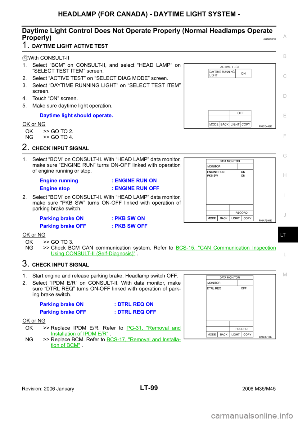
1. DAYTIME LIGHT ACTIVE TEST
With CONSULT-II
1. Select “BCM” on CONSULT-II, and select “HEAD LAMP” on
“SELECT TEST ITEM” screen.
2. Select “ACTIVE TEST” on “SELECT DIAG MODE” screen.
3. Select “DAYTIME RUNNING LIGHT” on “SELECT TEST ITEM”
screen.
4. Touch “ON” screen.
5. Make sure daytime light operation.
OK or NG
OK >> GO TO 2.
NG >> GO TO 4.
2. CHECK INPUT SIGNAL
1. Select “BCM” on CONSULT-II. With “HEAD LAMP” data monitor,
make sure “ENGINE RUN” turns ON-OFF linked with operation
of engine running or stop.
2. Select “BCM” on CONSULT-II. With “HEAD LAMP” data monitor,
make sure “PKB SW” turns ON-OFF linked with operation of
parking brake switch.
OK or NG
OK >> GO TO 3.
NG >> Check BCM CAN communication system. Refer to BCS-15, "
CAN Communication Inspection
Using CONSULT-II (Self-Diagnosis)" .
3. CHECK INPUT SIGNAL
1. Start engine and release parking brake. Headlamp switch OFF.
2. Select “IPDM E/R” on CONSULT-II. With data monitor, make
sure “DTRL REQ” turns ON-OFF linked with operation of park-
ing brake switch.
OK or NG
OK >> Replace IPDM E/R. Refer to PG-31, "Removal and
Installation of IPDM E/R" .
NG >> Replace BCM. Refer to BCS-17, "
Removal and Installa-
tion of BCM" . Daytime light should operate.
PKIC0442E
Engine running : ENGINE RUN ON
Engine stop : ENGINE RUN OFF
Parking brake ON : PKB SW ON
Parking brake OFF : PKB SW OFF
PKIA7591E
Parking brake ON : DTRL REQ ON
Parking brake OFF : DTRL REQ OFF
SKIB4913E
Page 4527 of 5621
LT-100
HEADLAMP (FOR CANADA) - DAYTIME LIGHT SYSTEM -
Revision: 2006 January2006 M35/M45
4. CHECK DAYTIME LIGHT RELAY POWER SUPPLY CIRCUIT
1. Turn ignition switch OFF.
2. Remove daytime light relay.
3. Check voltage between daytime light relay harness connector
E34 terminals 2, 5 and ground.
OK or NG
OK >> GO TO 5.
NG >> Repair harness or connector.
5. CHECK DAYTIME LIGHT RELAY
1. Apply battery voltage to daytime light relay terminals 1 and 2.
2. Check continuity between terminals 3 and 5.
OK or NG
OK >> GO TO 6.
NG >> Replace daytime light relay.
6. CHECK CIRCUIT BETWEEN DAYTIME LIGHT RELAY AND IPDM E/R
1. Disconnect IPDM E/R connector.
2. Check continuity between IPDM E/R harness connector (A) E9
terminal 58 and daytime light relay harness connector (B) E34
terminal 1.
OK or NG
OK >> GO TO 7.
NG >> Repair harness or connector.2, 5 – Ground : Battery voltage
SKIB4746E
3 – 5 : Continuity should exist.
SKIB4671E
58 – 1 : Continuity should exist.
SKIB4748E
Page 4528 of 5621
HEADLAMP (FOR CANADA) - DAYTIME LIGHT SYSTEM -
LT-101
C
D
E
F
G
H
I
J
L
MA
B
LT
Revision: 2006 January2006 M35/M45
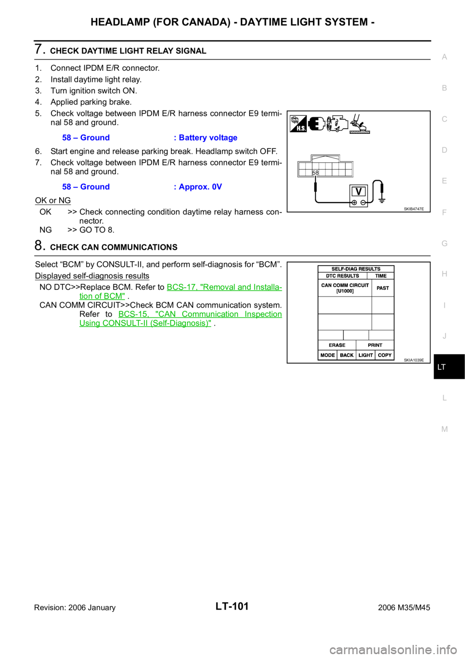
7. CHECK DAYTIME LIGHT RELAY SIGNAL
1. Connect IPDM E/R connector.
2. Install daytime light relay.
3. Turn ignition switch ON.
4. Applied parking brake.
5. Check voltage between IPDM E/R harness connector E9 termi-
nal 58 and ground.
6. Start engine and release parking break. Headlamp switch OFF.
7. Check voltage between IPDM E/R harness connector E9 termi-
nal 58 and ground.
OK or NG
OK >> Check connecting condition daytime relay harness con-
nector.
NG >> GO TO 8.
8. CHECK CAN COMMUNICATIONS
Select “BCM” by CONSULT-II, and perform self-diagnosis for “BCM”.
Displayed self-diagnosis results
NO DTC>>Replace BCM. Refer to BCS-17, "Removal and Installa-
tion of BCM" .
CAN COMM CIRCUIT>>Check BCM CAN communication system.
Refer to BCS-15, "
CAN Communication Inspection
Using CONSULT-II (Self-Diagnosis)" . 58 – Ground : Battery voltage
58 – Ground : Approx. 0V
SKIB4747E
SKIA1039E
Page 4529 of 5621
LT-102
HEADLAMP (FOR CANADA) - DAYTIME LIGHT SYSTEM -
Revision: 2006 January2006 M35/M45
Headlamp High Beam Does Not Illuminate (Both Sides)NKS003PL
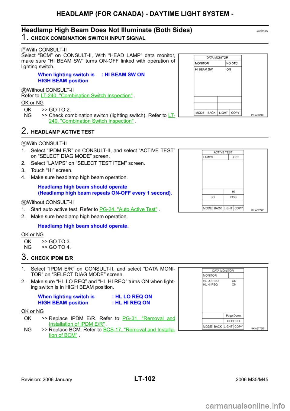
1. CHECK COMBINATION SWITCH INPUT SIGNAL
With CONSULT-II
Select “BCM” on CONSULT-II, With “HEAD LAMP” data monitor,
make sure “HI BEAM SW” turns ON-OFF linked with operation of
lighting switch.
Without CONSULT-II
Refer to LT- 2 4 0 , "
Combination Switch Inspection" .
OK or NG
OK >> GO TO 2.
NG >> Check combination switch (lighting switch). Refer to LT-
240, "Combination Switch Inspection" .
2. HEADLAMP ACTIVE TEST
With CONSULT-II
1. Select “IPDM E/R” on CONSULT-II, and select “ACTIVE TEST”
on “SELECT DIAG MODE” screen.
2. Select “LAMPS” on “SELECT TEST ITEM” screen.
3. Touch “HI” screen.
4. Make sure headlamp high beam operation.
Without CONSULT-II
1. Start auto active test. Refer to PG-24, "
Auto Active Test" .
2. Make sure headlamp high beam operation.
OK or NG
OK >> GO TO 3.
NG >> GO TO 4.
3. CHECK IPDM E/R
1. Select “IPDM E/R” on CONSULT-II, and select “DATA MONI-
TOR” on “SELECT DIAG MODE” screen.
2. Make sure “HL LO REQ” and “HL HI REQ” turns ON when light-
ing switch is in HIGH BEAM position.
OK or NG
OK >> Replace IPDM E/R. Refer to PG-31, "Removal and
Installation of IPDM E/R" .
NG >> Replace BCM. Refer to BCS-17, "
Removal and Installa-
tion of BCM" . When lighting switch is
HIGH BEAM position: HI BEAM SW ON
PKIA6324E
Headlamp high beam should operate
(Headlamp high beam repeats ON-OFF every 1 second).
Headlamp high beam should operate.
SKIA5774E
When lighting switch is
HIGH BEAM position: HL LO REQ ON
: HL HI REQ ON
SKIA5775E
Page 4530 of 5621
HEADLAMP (FOR CANADA) - DAYTIME LIGHT SYSTEM -
LT-103
C
D
E
F
G
H
I
J
L
MA
B
LT
Revision: 2006 January2006 M35/M45
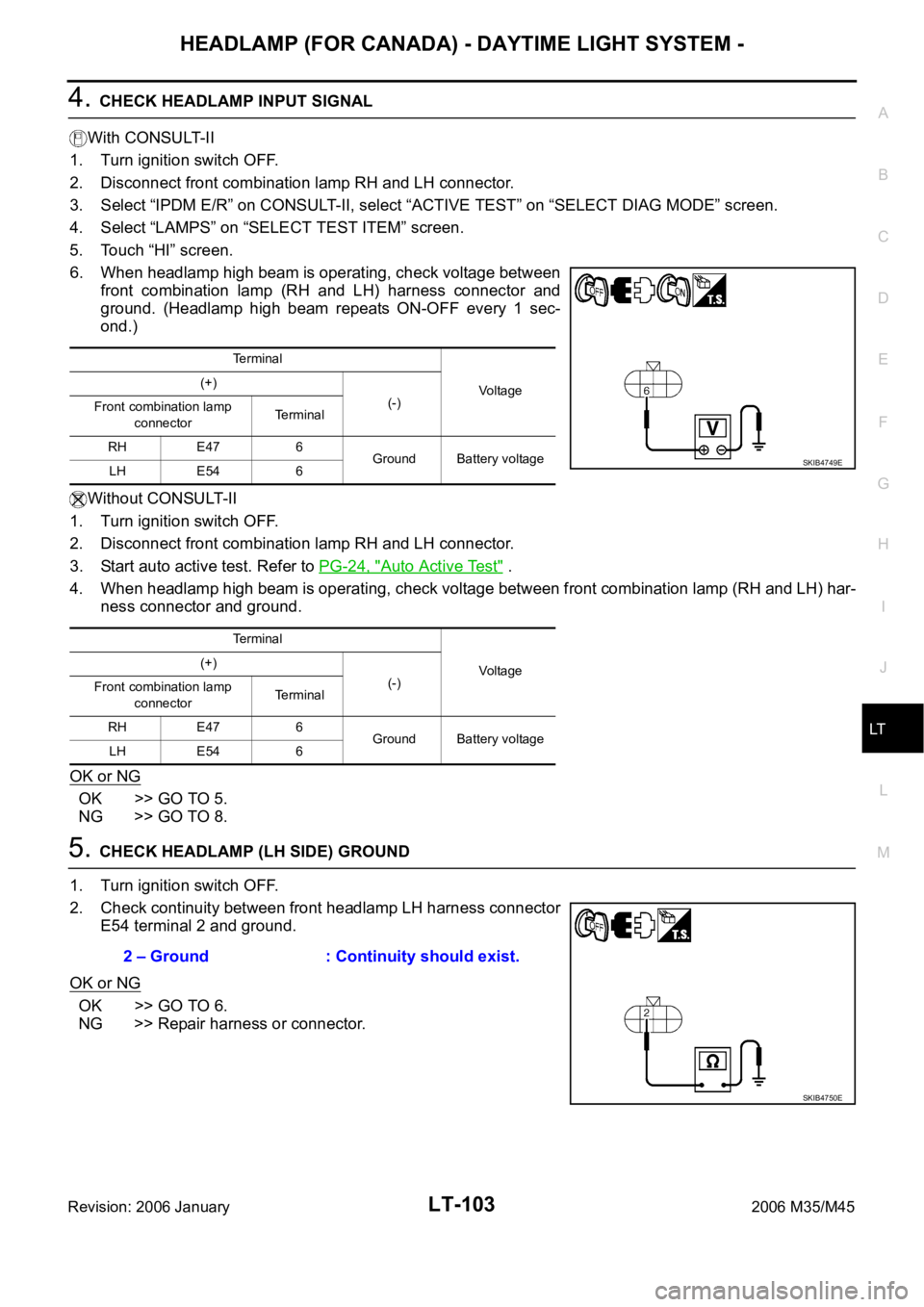
4. CHECK HEADLAMP INPUT SIGNAL
With CONSULT-II
1. Turn ignition switch OFF.
2. Disconnect front combination lamp RH and LH connector.
3. Select “IPDM E/R” on CONSULT-II, select “ACTIVE TEST” on “SELECT DIAG MODE” screen.
4. Select “LAMPS” on “SELECT TEST ITEM” screen.
5. Touch “HI” screen.
6. When headlamp high beam is operating, check voltage between
front combination lamp (RH and LH) harness connector and
ground. (Headlamp high beam repeats ON-OFF every 1 sec-
ond.)
Without CONSULT-II
1. Turn ignition switch OFF.
2. Disconnect front combination lamp RH and LH connector.
3. Start auto active test. Refer to PG-24, "
Auto Active Test" .
4. When headlamp high beam is operating, check voltage between front combination lamp (RH and LH) har-
ness connector and ground.
OK or NG
OK >> GO TO 5.
NG >> GO TO 8.
5. CHECK HEADLAMP (LH SIDE) GROUND
1. Turn ignition switch OFF.
2. Check continuity between front headlamp LH harness connector
E54 terminal 2 and ground.
OK or NG
OK >> GO TO 6.
NG >> Repair harness or connector.
Terminal
Vo l ta g e (+)
(-)
Front combination lamp
connectorTerminal
RH E47 6
Ground Battery voltage
LH E54 6
Terminal
Vo l ta g e (+)
(-)
Front combination lamp
connectorTerminal
RH E47 6
Ground Battery voltage
LH E54 6
SKIB4749E
2 – Ground : Continuity should exist.
SKIB4750E
Page 4531 of 5621
LT-104
HEADLAMP (FOR CANADA) - DAYTIME LIGHT SYSTEM -
Revision: 2006 January2006 M35/M45
6. CHECK HEADLAMP (RH SIDE) GROUND
1. Remove daytime light relay.
2. Check continuity between front headlamp RH harness connec-
tor (A) E47 terminal 2 and daytime light relay harness connector
(B) E34 terminal 3.
3. Check continuity between daytime light relay harness connector
E34 terminal 4 and ground.
OK or NG
OK >> GO TO 7.
NG >> Repair harness or connector.
7. CHECK DAYTIME LIGHT RELAY
Check continuity between terminal 3 and 4.
OK >> Check headlamp bulb and connecting condition combi-
nation lamp terminal connector.
NG >> Replace daytime light relay.2 – 3 : Continuity should exist.
SKIB4751E
4 – Ground : Continuity should exist.
SKIB4674E
3 – 4 : Continuity should exist.
SKIB4660E
Page 4532 of 5621
HEADLAMP (FOR CANADA) - DAYTIME LIGHT SYSTEM -
LT-105
C
D
E
F
G
H
I
J
L
MA
B
LT
Revision: 2006 January2006 M35/M45
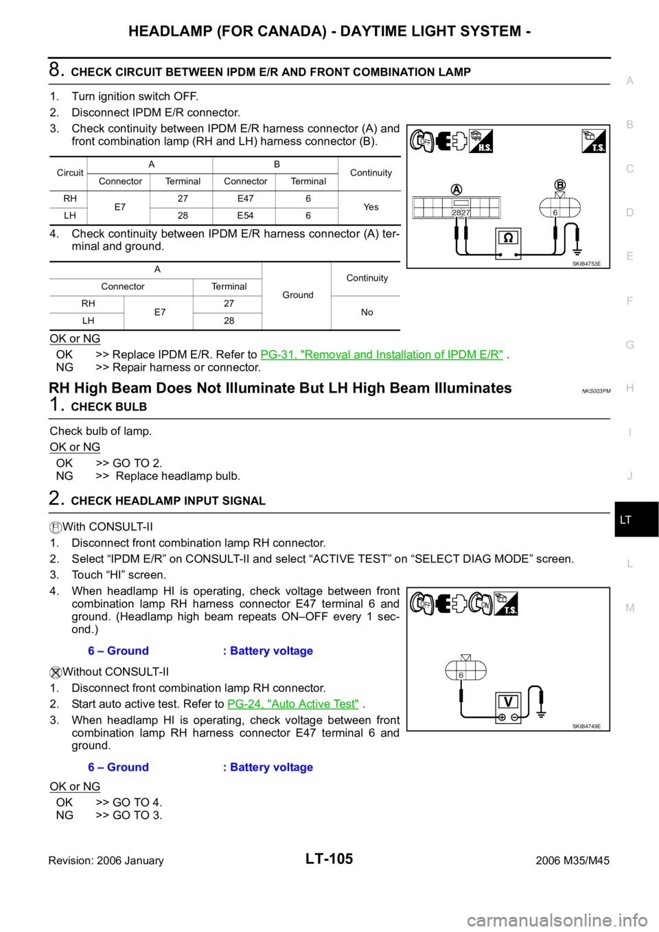
8. CHECK CIRCUIT BETWEEN IPDM E/R AND FRONT COMBINATION LAMP
1. Turn ignition switch OFF.
2. Disconnect IPDM E/R connector.
3. Check continuity between IPDM E/R harness connector (A) and
front combination lamp (RH and LH) harness connector (B).
4. Check continuity between IPDM E/R harness connector (A) ter-
minal and ground.
OK or NG
OK >> Replace IPDM E/R. Refer to PG-31, "Removal and Installation of IPDM E/R" .
NG >> Repair harness or connector.
RH High Beam Does Not Illuminate But LH High Beam IlluminatesNKS003PM
1. CHECK BULB
Check bulb of lamp.
OK or NG
OK >> GO TO 2.
NG >> Replace headlamp bulb.
2. CHECK HEADLAMP INPUT SIGNAL
With CONSULT-II
1. Disconnect front combination lamp RH connector.
2. Select “IPDM E/R” on CONSULT-II and select “ACTIVE TEST” on “SELECT DIAG MODE” screen.
3. Touch “HI” screen.
4. When headlamp HI is operating, check voltage between front
combination lamp RH harness connector E47 terminal 6 and
ground. (Headlamp high beam repeats ON–OFF every 1 sec-
ond.)
Without CONSULT-II
1. Disconnect front combination lamp RH connector.
2. Start auto active test. Refer to PG-24, "
Auto Active Test" .
3. When headlamp HI is operating, check voltage between front
combination lamp RH harness connector E47 terminal 6 and
ground.
OK or NG
OK >> GO TO 4.
NG >> GO TO 3.
CircuitAB
Continuity
Connector Terminal Connector Terminal
RH
E727 E47 6
Ye s
LH 28 E54 6
A
GroundContinuity
Connector Terminal
RH
E727
No
LH 28
SKIB4753E
6 – Ground : Battery voltage
6 – Ground : Battery voltage
SKIB4749E