2006 INFINITI M35 capacity
[x] Cancel search: capacityPage 3188 of 5621
![INFINITI M35 2006 Factory Service Manual CYLINDER BLOCK
EM-125
[VQ35DE]
C
D
E
F
G
H
I
J
K
L
MA
EM
Revision: 2006 January2006 M35/M45
CAUTION:
Do not disassemble drive plate.
Never place drive plate with signal plate facing down.
When handlin INFINITI M35 2006 Factory Service Manual CYLINDER BLOCK
EM-125
[VQ35DE]
C
D
E
F
G
H
I
J
K
L
MA
EM
Revision: 2006 January2006 M35/M45
CAUTION:
Do not disassemble drive plate.
Never place drive plate with signal plate facing down.
When handlin](/manual-img/42/57023/w960_57023-3187.png)
CYLINDER BLOCK
EM-125
[VQ35DE]
C
D
E
F
G
H
I
J
K
L
MA
EM
Revision: 2006 January2006 M35/M45
CAUTION:
Do not disassemble drive plate.
Never place drive plate with signal plate facing down.
When handling signal plate, take care not to damage or
scratch it.
Handle signal plate in a manner that prevents it from
becoming magnetized.
3. Lift the engine with hoist to install it onto the widely use engine stand.
CAUTION:
Use an engine stand that has a load capacity [220 kg (441 lb) or more] large enough for supporting
the engine weight.
If the load capacity of the stand is not adequate, remove the following parts beforehand to reduce the
potential risk of overturning the stand.
–Remove intake manifold collector. Refer to EM-19, "INTAKE MANIFOLD COLLECTOR" .
–Remove intake manifold. Refer to EM-24, "INTAKE MANIFOLD" .
–Remove fuel injector and fuel tube assembly. Refer to EM-45, "FUEL INJECTOR AND FUEL TUBE" .
–Remove ignition coil. Refer to EM-42, "IGNITION COIL" .
–Remove rocker cover. Refer to EM-51, "ROCKER COVER" .
–Remove exhaust manifold. Refer to EM-26, "EXHAUST MANIFOLD" .
–Other removable brackets.
NOTE:
The figure shows an example of widely use engine stand that
can hold mating surface of transmission with drive plate
removed.
CAUTION:
Before removing the hanging chains, make sure the
engine stand is stable and there is no risk of overturning.
4. Drain engine oil. Refer to LU-9, "
Changing Engine Oil" .
SEM760G
PBIC0085E
Page 3313 of 5621
![INFINITI M35 2006 Factory Service Manual EM-250
[VK45DE]
CYLINDER BLOCK
Revision: 2006 January2006 M35/M45
Disassembly and AssemblyNBS004PN
DISASSEMBLY
NOTE:
Explained here is how to disassemble with engine stand supporting transmission su INFINITI M35 2006 Factory Service Manual EM-250
[VK45DE]
CYLINDER BLOCK
Revision: 2006 January2006 M35/M45
Disassembly and AssemblyNBS004PN
DISASSEMBLY
NOTE:
Explained here is how to disassemble with engine stand supporting transmission su](/manual-img/42/57023/w960_57023-3312.png)
EM-250
[VK45DE]
CYLINDER BLOCK
Revision: 2006 January2006 M35/M45
Disassembly and AssemblyNBS004PN
DISASSEMBLY
NOTE:
Explained here is how to disassemble with engine stand supporting transmission surface. When using differ-
ent type of engine stand, note with difference in steps and etc.
1. Remove engine assembly from vehicle, and separate front suspension member, transmission from
engine. Refer to EM-244, "
ENGINE ASSEMBLY" .
2. Remove the parts that may restrict installation of engine to widely use engine stand.
NOTE:
The procedure is described assuming that you use widely use engine holding the surface, to which trans-
mission is installed.
a. Remove drive plate.
Holding ring gear with ring gear stopper (SST).
Loosen mounting bolts diagonally order.
CAUTION:
Do not disassemble drive plate.
Do not place drive plate with signal plate facing down.
When handling signal plate, take care not to damage or
scratch it.
Handle signal plate in a manner that prevents it from
becoming magnetized.
b. Remove rear plate.
3. Lift engine with hoist to install it onto widely use engine stand.
CAUTION:
Use engine stand that has a load capacity [approximately 240kg (529 lb) or more] large enough for
supporting the engine weight.
If the load capacity of stand is not adequate, remove the following parts beforehand to reduce the
potential risk of overturning stand.
–Intake manifolds (upper and lower); Refer to EM-179, "INTAKE MANIFOLD" .
–Exhaust manifold and three way catalyst; Refer to EM-183, "EXHAUST MANIFOLD AND THREE WAY
CATALYST" .
13. Piston pin 14. Connecting rod bearing 15. Connecting rod bearing cap
16. Block heater protector 17. Connector cap 18. Cylinder block heater
19. Gasket 20. Main bearing cap 21. Thrust bearing
22. Main bearing 23. Rear plate 24. Crankshaft
25. Pilot convertor 26. Drive plate 27. Thrust bearing
28. Side bolt 29. Reinforcement plate 30. Crankshaft position sensor (POS)
31. O-ring 32. Rear oil seal 33. Rear oil seal retainer
PBIC1656E
PBIC2367E
Page 3385 of 5621

FFD-8
DIFFERENTIAL GEAR OIL
Revision: 2006 January2006 M35/M45
DIFFERENTIAL GEAR OILPFP:KLD30
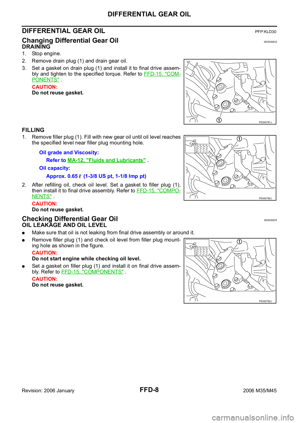
Changing Differential Gear OilNDS000EQ
DRAINING
1. Stop engine.
2. Remove drain plug (1) and drain gear oil.
3. Set a gasket on drain plug (1) and install it to final drive assem-
bly and tighten to the specified torque. Refer to FFD-15, "
COM-
PONENTS" .
CAUTION:
Do not reuse gasket.
FILLING
1. Remove filler plug (1). Fill with new gear oil until oil level reaches
the specified level near filler plug mounting hole.
2. After refilling oil, check oil level. Set a gasket to filler plug (1),
then install it to final drive assembly. Refer to FFD-15, "
COMPO-
NENTS" .
CAUTION:
Do not reuse gasket.
Checking Differential Gear OilNDS000ER
OIL LEAKAGE AND OIL LEVEL
Make sure that oil is not leaking from final drive assembly or around it.
Remove filler plug (1) and check oil level from filler plug mount-
ing hole as shown in the figure.
CAUTION:
Do not start engine while checking oil level.
Set a gasket on filler plug (1) and install it on final drive assem-
bly. Refer to FFD-15, "
COMPONENTS" .
CAUTION:
Do not reuse gasket.
PDIA0781J
Oil grade and Viscosity:
Refer to MA-12, "
Fluids and Lubricants" .
Oil capacity:
Approx. 0.65 (1-3/8 US pt, 1-1/8 Imp pt)
PDIA0782J
PDIA0782J
Page 3412 of 5621

SERVICE DATA AND SPECIFICATIONS (SDS)
FFD-35
C
E
F
G
H
I
J
K
L
MA
B
FFD
Revision: 2006 January2006 M35/M45
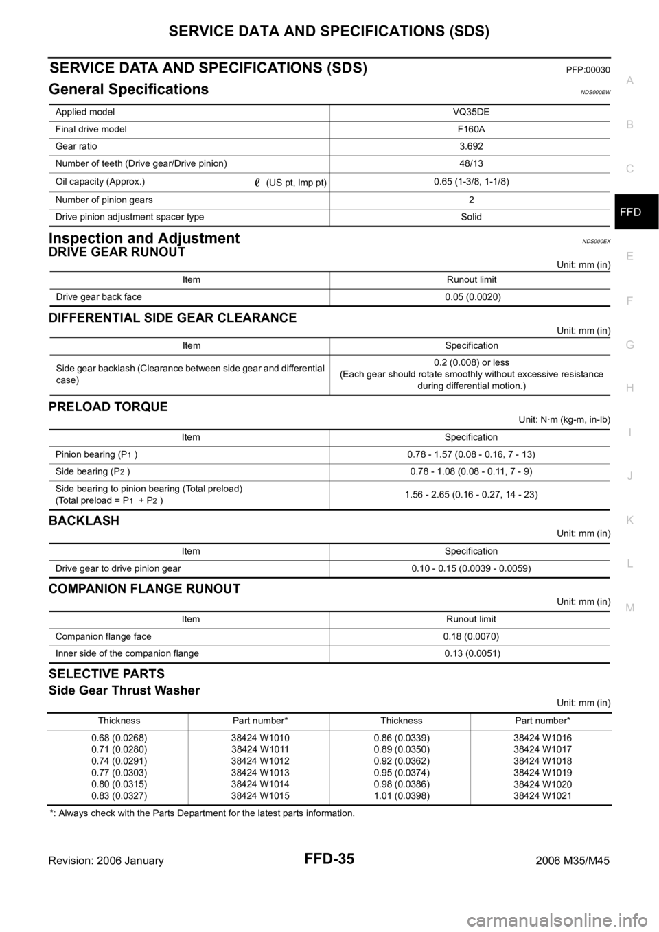
SERVICE DATA AND SPECIFICATIONS (SDS)PFP:00030
General SpecificationsNDS000EW
Inspection and AdjustmentNDS000EX
DRIVE GEAR RUNOUT
Unit: mm (in)
DIFFERENTIAL SIDE GEAR CLEARANCE
Unit: mm (in)
PRELOAD TORQUE
Unit: Nꞏm (kg-m, in-lb)
BACKLASH
Unit: mm (in)
COMPANION FLANGE RUNOUT
Unit: mm (in)
SELECTIVE PARTS
Side Gear Thrust Washer
Unit: mm (in)
*: Always check with the Parts Department for the latest parts information. Applied modelVQ35DE
Final drive modelF160A
Gear ratio3.692
Number of teeth (Drive gear/Drive pinion) 48/13
Oil capacity (Approx.)
(US pt, lmp pt)0.65 (1-3/8, 1-1/8)
Number of pinion gears2
Drive pinion adjustment spacer type Solid
Item Runout limit
Drive gear back face 0.05 (0.0020)
Item Specification
Side gear backlash (Clearance between side gear and differential
case)0.2 (0.008) or less
(Each gear should rotate smoothly without excessive resistance
during differential motion.)
Item Specification
Pinion bearing (P
1 ) 0.78 - 1.57 (0.08 - 0.16, 7 - 13)
Side bearing (P
2 ) 0.78 - 1.08 (0.08 - 0.11, 7 - 9)
Side bearing to pinion bearing (Total preload)
(Total preload = P
1 + P2 )1.56 - 2.65 (0.16 - 0.27, 14 - 23)
Item Specification
Drive gear to drive pinion gear 0.10 - 0.15 (0.0039 - 0.0059)
Item Runout limit
Companion flange face 0.18 (0.0070)
Inner side of the companion flange 0.13 (0.0051)
Thickness Part number* Thickness Part number*
0.68 (0.0268)
0.71 (0.0280)
0.74 (0.0291)
0.77 (0.0303)
0.80 (0.0315)
0.83 (0.0327)38424 W1010
38424 W1011
38424 W1012
38424 W1013
38424 W1014
38424 W10150.86 (0.0339)
0.89 (0.0350)
0.92 (0.0362)
0.95 (0.0374)
0.98 (0.0386)
1.01 (0.0398)38424 W1016
38424 W1017
38424 W1018
38424 W1019
38424 W1020
38424 W1021
Page 3426 of 5621

SERVICE DATA AND SPECIFICATIONS (SDS)
FL-13
C
D
E
F
G
H
I
J
K
L
MA
FL
Revision: 2006 January2006 M35/M45
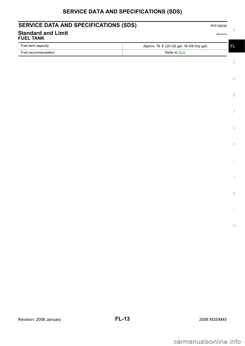
SERVICE DATA AND SPECIFICATIONS (SDS)PFP:00030
Standard and LimitNBS005RG
FUEL TANK
Fuel tank capacity
Approx. 76 (20 US gal, 16-5/8 Imp gal)
Fuel recommendation Refer to GI-6
Page 4744 of 5621

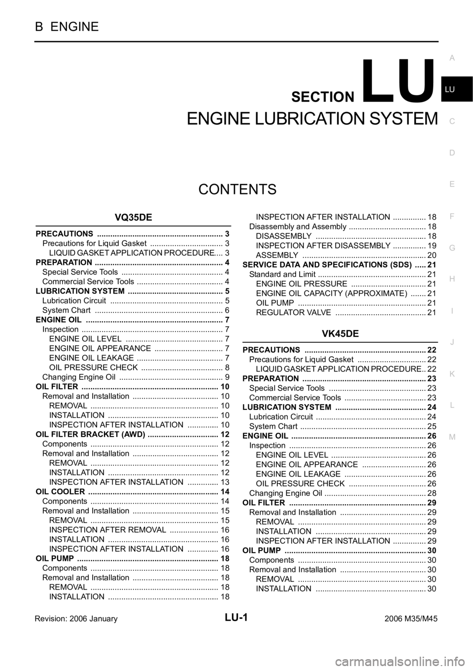
LU-1
ENGINE LUBRICATION SYSTEM
B ENGINE
CONTENTS
C
D
E
F
G
H
I
J
K
L
M
SECTION LU
A
LU
Revision: 2006 January2006 M35/M45
ENGINE LUBRICATION SYSTEM
VQ35DE
PRECAUTIONS .......................................................... 3
Precautions for Liquid Gasket .................................. 3
LIQUID GASKET APPLICATION PROCEDURE ..... 3
PREPARATION ........................................................... 4
Special Service Tools ............................................... 4
Commercial Service Tools ........................................ 4
LUBRICATION SYSTEM ............................................ 5
Lubrication Circuit .................................................... 5
System Chart ........................................................... 6
ENGINE OIL ............................................................... 7
Inspection ................................................................. 7
ENGINE OIL LEVEL ............................................. 7
ENGINE OIL APPEARANCE ................................ 7
ENGINE OIL LEAKAGE ........................................ 7
OIL PRESSURE CHECK ...................................... 8
Changing Engine Oil ................................................ 9
OIL FILTER ............................................................... 10
Removal and Installation ........................................ 10
REMOVAL ........................................................
... 10
INSTALLATION ................................................... 10
INSPECTION AFTER INSTALLATION ............... 10
OIL FILTER BRACKET (AWD) ................................. 12
Components ........................................................... 12
Removal and Installation ........................................ 12
REMOVAL ........................................................
... 12
INSTALLATION ................................................... 12
INSPECTION AFTER INSTALLATION ............... 13
OIL COOLER ............................................................ 14
Components ........................................................... 14
Removal and Installation ........................................ 15
REMOVAL ........................................................
... 15
INSPECTION AFTER REMOVAL ....................... 16
INSTALLATION ................................................... 16
INSPECTION AFTER INSTALLATION ............... 16
OIL PUMP ................................................................. 18
Components ........................................................... 18
Removal and Installation ........................................ 18
REMOVAL ........................................................
... 18
INSTALLATION ................................................... 18INSPECTION AFTER INSTALLATION ................ 18
Disassembly and Assembly .................................... 18
DISASSEMBLY ................................................... 18
INSPECTION AFTER DISASSEMBLY ................ 19
ASSEMBLY ......................................................... 20
SERVICE DATA AND SPECIFICATIONS (SDS) ...... 21
Standard and Limit .................................................. 21
ENGINE OIL PRESSURE ................................... 21
ENGINE OIL CAPACITY (APPROXIMATE) ........ 21
OIL PUMP ........................................................... 21
REGULATOR VALVE .......................................... 21
VK45DE
PRECAUTIONS ........................................................ 22
Precautions for Liquid Gasket ................................ 22
LIQUID GASKET APPLICATION PROCEDURE ... 22
PREPARATION ......................................................... 23
Special Service Tools ............................................. 23
Commercial Service Tools ...................................... 23
LUBRICATION SYSTEM .......................................... 24
Lubrication Circuit ................................................... 24
System Chart .......................................................... 25
ENGINE OIL .............................................................. 26
Inspection ............................................................... 26
ENGINE OIL LEVEL ............................................ 26
ENGINE OIL APPEARANCE .............................. 26
ENGINE OIL LEAKAGE ...................................... 26
OIL PRESSURE CHECK .................................... 26
Changing Engine Oil ............................................
... 28
OIL FILTER ............................................................... 29
Removal and Installation ........................................ 29
REMOVAL ........................................................
... 29
INSTALLATION ................................................... 29
INSPECTION AFTER INSTALLATION ................ 29
OIL PUMP ................................................................. 30
Components ........................................................... 30
Removal and Installation ........................................ 30
REMOVAL ........................................................
... 30
INSTALLATION ................................................... 30
Page 4745 of 5621

LU-2Revision: 2006 January2006 M35/M45 INSPECTION AFTER INSTALLATION ................ 31
Disassembly and Assembly .................................... 31
DISASSEMBLY ................................................... 31
INSPECTION AFTER DISASSEMBLY ................ 31
ASSEMBLY ......................................................... 32SERVICE DATA AND SPECIFICATIONS (SDS) ...... 33
Standard and Limit .................................................. 33
ENGINE OIL PRESSURE .................................... 33
ENGINE OIL CAPACITY (APPROXIMATE) ........ 33
OIL PUMP ............................................................ 33
REGULATOR VALVE ........................................... 33
Page 4752 of 5621
![INFINITI M35 2006 Factory Service Manual ENGINE OIL
LU-9
[VQ35DE]
C
D
E
F
G
H
I
J
K
L
MA
LU
Revision: 2006 January2006 M35/M45
a. Remove old liquid gasket adhering to oil pressure switch and the mating surface.
b. Apply liquid gasket and tig INFINITI M35 2006 Factory Service Manual ENGINE OIL
LU-9
[VQ35DE]
C
D
E
F
G
H
I
J
K
L
MA
LU
Revision: 2006 January2006 M35/M45
a. Remove old liquid gasket adhering to oil pressure switch and the mating surface.
b. Apply liquid gasket and tig](/manual-img/42/57023/w960_57023-4751.png)
ENGINE OIL
LU-9
[VQ35DE]
C
D
E
F
G
H
I
J
K
L
MA
LU
Revision: 2006 January2006 M35/M45
a. Remove old liquid gasket adhering to oil pressure switch and the mating surface.
b. Apply liquid gasket and tighten oil pressure switch to the specification.
Use Genuine RTV Silicone Sealant or equivalent. Refer to GI-48, "
RECOMMENDED CHEMICAL
PRODUCTS AND SEALANTS" .
c. After warming up engine, make sure there is no leakage of engine oil with running engine.
Changing Engine OilNBS004PX
WAR NING :
Be careful not to get burn yourself, as engine oil may be hot.
Prolonged and repeated contact with used engine oil may cause skin cancer; try to avoid direct
skin contact with used engine oil. If skin contact is made, wash thoroughly with soap or hand
cleaner as soon as possible.
1. Warm up the engine, and check for engine oil leakage from engine components. Refer to LU-7, "
ENGINE
OIL LEAKAGE" .
2. Stop the engine and wait for 10 minutes.
3. Loosen oil filler cap.
4. Remove mounting bolts, and then pull down the rear of front
engine undercover (1) and secure it using clip.
5. Remove drain plug (2) and then drain engine oil.
6. Install drain plug with new washer. Refer to EM-29, "
OIL PAN AND OIL STRAINER" .
CAUTION:
Be sure to clean drain plug and install with new washer.
7. Refill with new engine oil.
Engine oil specification and viscosity:
Refer to MA-12, "
RECOMMENDED FLUIDS AND LUBRICANTS" .
Engine oil capacity (Approximate):
Unit: (US qt, lmp qt)
CAUTION:
When filling engine oil, do not pull out oil level gauge.
The refill capacity depends on the engine oil temperature and drain time. Use these specifica-
tions for reference only.
Always use oil level gauge to determine the proper amount of engine oil in engine.
8. Warm up the engine and check area around drain plug and oil filter for engine oil leakage.
9. Stop the engine and wait for 10 minutes.
10. Check the engine oil level. Refer to LU-7, "
ENGINE OIL LEVEL" . Oil pressure switch:
: 14.8 Nꞏm (1.5 kg-m, 11 ft-lb)
KBIA3593J
Oil pan drain plug:
: 34.3 Nꞏm (3.5 kg-m, 25 ft-lb)
Drain and refill With oil filter change 4.7 (5, 4-1/8)
Without oil filter change 4.4 (4-5/8, 3-7/8)
Dry engine (Overhaul)5.4 (5-3/4, 4-3/4)