2006 INFINITI M35 sensor
[x] Cancel search: sensorPage 1283 of 5621

BR-8
BRAKE PEDAL
Revision: 2006 January2006 M35/M45
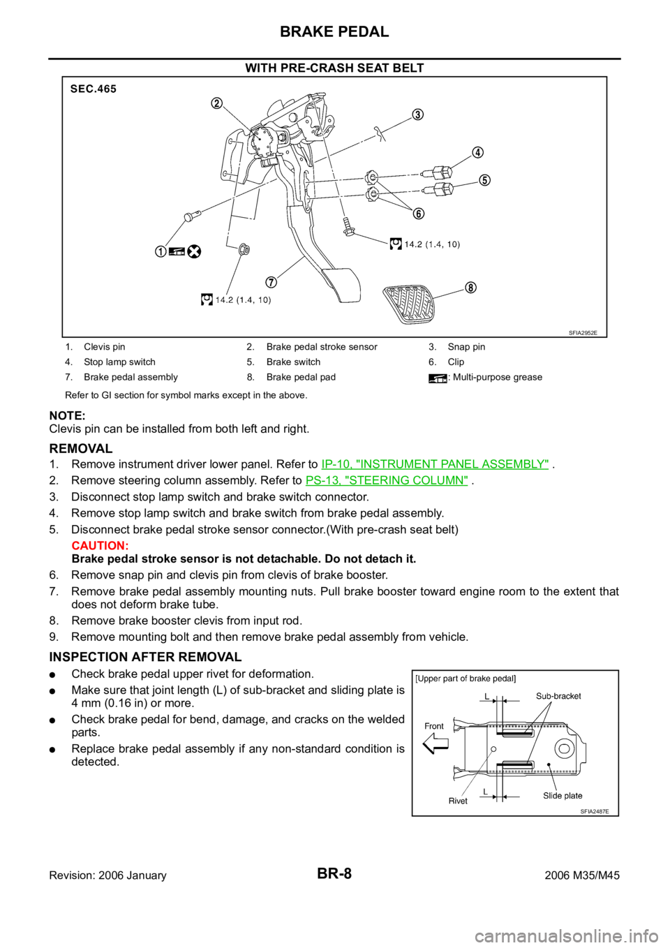
WITH PRE-CRASH SEAT BELT
NOTE:
Clevis pin can be installed from both left and right.
REMOVAL
1. Remove instrument driver lower panel. Refer to IP-10, "INSTRUMENT PANEL ASSEMBLY" .
2. Remove steering column assembly. Refer to PS-13, "
STEERING COLUMN" .
3. Disconnect stop lamp switch and brake switch connector.
4. Remove stop lamp switch and brake switch from brake pedal assembly.
5. Disconnect brake pedal stroke sensor connector.(With pre-crash seat belt)
CAUTION:
Brake pedal stroke sensor is not detachable. Do not detach it.
6. Remove snap pin and clevis pin from clevis of brake booster.
7. Remove brake pedal assembly mounting nuts. Pull brake booster toward engine room to the extent that
does not deform brake tube.
8. Remove brake booster clevis from input rod.
9. Remove mounting bolt and then remove brake pedal assembly from vehicle.
INSPECTION AFTER REMOVAL
Check brake pedal upper rivet for deformation.
Make sure that joint length (L) of sub-bracket and sliding plate is
4 mm (0.16 in) or more.
Check brake pedal for bend, damage, and cracks on the welded
parts.
Replace brake pedal assembly if any non-standard condition is
detected.
SFIA2952E
1. Clevis pin 2. Brake pedal stroke sensor 3. Snap pin
4. Stop lamp switch 5. Brake switch 6. Clip
7. Brake pedal assembly 8. Brake pedal pad : Multi-purpose grease
Refer to GI section for symbol marks except in the above.
SFIA2487E
Page 1298 of 5621

FRONT DISC BRAKE
BR-23
C
D
E
G
H
I
J
K
L
MA
B
BR
Revision: 2006 January2006 M35/M45
FRONT DISC BRAKEPFP:41000
On-Board InspectionNFS000PB
PAD WEAR INSPECTION
Check pad thickness from an inspection hole on cylinder body.
Check using a scale if necessary.
ComponentsNFS000PC
WAR NING :
Clean dust on caliper and brake pad with a vacuum dust collector to minimize the hazard of air borne
particles or other materials.
CAUTION:
While removing cylinder body, do not depress brake pedal because piston will pop out. Standard thickness : 11.0 mm (0.433 in)
Repair limit thickness : 2.0 mm (0.079 in)
MAA0439D
1. Union bolt 2. Copper washer 3. Brake hose
4. Cap 5. Bleed valve 6. Sliding pin bolt
7. Piston seal 8. Piston 9. Piston boot
10. Cylinder body 11. Sliding pin 12. Torque member mounting bolt
13. Washer 14. Sliding pin boot 15. Bushing
16. Torque member 17. Inner shim cover 18. Inner shim
19. Inner pad 20. Pad retainer 21. Pad wear sensor
22. Outer pad 23. Outer shim 24. Outer shim cover
Refer to GI-11, "
Components" and the followings for the symbols in the figure.
1: Apply rubber grease.
2: Apply PBC (Poly Butyl Cuprysil) grease or silicone-based grease.
3: Apply polyglycol ether based lubricant.
: Apply brake fluid.
PFIA0820E
Page 1299 of 5621

BR-24
FRONT DISC BRAKE
Revision: 2006 January2006 M35/M45
It is not necessary to remove bolts on torque member and brake hose except for disassembly or
replacement of caliper assembly. In this case, hang cylinder body with a wire so as not to stretch
brake hose.
Do not damage piston boot.
If any shim is subject to serious corrosion, replace it with a new one.
Always replace shim and shim cover as a set when replacing brake pads.
Keep rotor free from brake fluid.
Burnish the brake pads and disc rotor mutually contacting surfaces, after refinishing or replacing
rotors, after replacing pads, or if a soft pedal occurs at very low mileage. Refer to BR-28, "
BRAKE
BURNISHING PROCEDURE" .
Removal and Installation of Brake PadNFS000PD
REMOVAL
1. Remove tires from vehicle with power tool.
2. Remove lower sliding pin bolt.
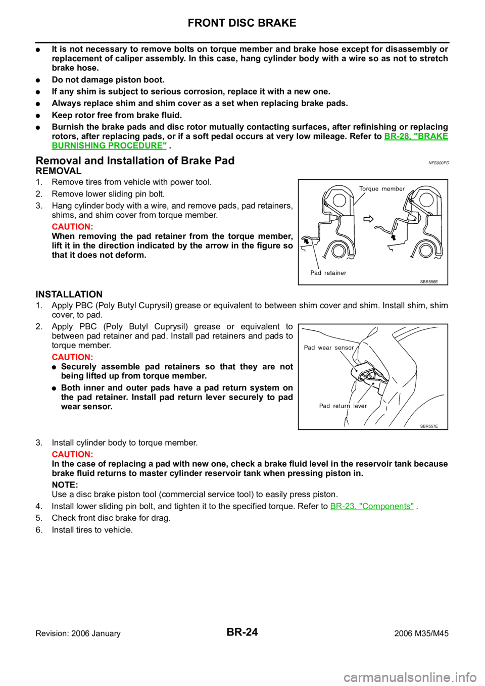
3. Hang cylinder body with a wire, and remove pads, pad retainers,
shims, and shim cover from torque member.
CAUTION:
When removing the pad retainer from the torque member,
lift it in the direction indicated by the arrow in the figure so
that it does not deform.
INSTALLATION
1. Apply PBC (Poly Butyl Cuprysil) grease or equivalent to between shim cover and shim. Install shim, shim
cover, to pad.
2. Apply PBC (Poly Butyl Cuprysil) grease or equivalent to
between pad retainer and pad. Install pad retainers and pads to
torque member.
CAUTION:
Securely assemble pad retainers so that they are not
being lifted up from torque member.
Both inner and outer pads have a pad return system on
the pad retainer. Install pad return lever securely to pad
wear sensor.
3. Install cylinder body to torque member.
CAUTION:
In the case of replacing a pad with new one, check a brake fluid level in the reservoir tank because
brake fluid returns to master cylinder reservoir tank when pressing piston in.
NOTE:
Use a disc brake piston tool (commercial service tool) to easily press piston.
4. Install lower sliding pin bolt, and tighten it to the specified torque. Refer to BR-23, "
Components" .
5. Check front disc brake for drag.
6. Install tires to vehicle.
SBR556E
SBR557E
Page 1304 of 5621

REAR DISC BRAKE
BR-29
C
D
E
G
H
I
J
K
L
MA
B
BR
Revision: 2006 January2006 M35/M45
REAR DISC BRAKEPFP:44000
On-Board InspectionNFS000PG
PAD WEAR INSPECTION
Check pad thickness from an inspection hole on cylinder body.
Check using a scale if necessary.
ComponentsNFS000PH
Standard
Standard thickness : 8.5 mm (0.335 in)
Repair limit thickness : 2.0 mm (0.079 in)
BRA0010D
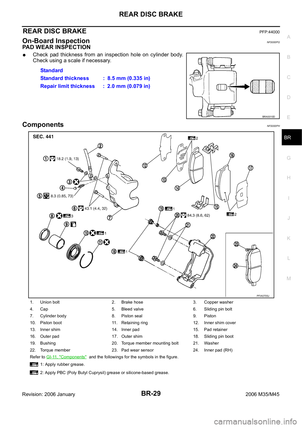
1. Union bolt 2. Brake hose 3. Copper washer
4. Cap 5. Bleed valve 6. Sliding pin bolt
7. Cylinder body 8. Piston seal 9. Piston
10. Piston boot 11. Retaining ring 12. Inner shim cover
13. Inner shim 14. Inner pad 15. Pad retainer
16. Outer pad 17. Outer shim 18. Sliding pin boot
19. Bushing 20. Torque member mounting bolt 21. Washer
22. Torque member 23. Pad wear sensor 24. Inner pad (RH)
Refer to GI-11, "
Components" and the followings for the symbols in the figure.
1: Apply rubber grease.
2: Apply PBC (Poly Butyl Cuprysil) grease or silicone-based grease.
PFIA0705J
Page 1312 of 5621

BRC-1
BRAKE CONTROL SYSTEM
F BRAKES
CONTENTS
C
D
E
G
H
I
J
K
L
M
SECTION BRC
A
B
BRC
Revision: 2006 January2006 M35/M45
BRAKE CONTROL SYSTEM
VDC/TCS/ABS
PRECAUTIONS .......................................................... 3
Precautions for Supplemental Restraint System
(SRS) “AIR BAG” and “SEAT BELT PRE-TEN-
SIONER” .................................................................. 3
Precautions for Procedures without Cowl Top Cover ..... 3
Precautions for Brake System .................................. 3
Precautions for Brake Control .................................. 4
PREPARATION ........................................................... 5
Special Service Tools ............................................... 5
Commercial Service Tools ........................................ 5
ON-VEHICLE SERVICE ............................................. 6
Adjustment of Steering Angle Sensor Neutral Posi-
tion ........................................................................... 6
SYSTEM DESCRIPTION ............................................ 7
System Diagram ....................................................... 7
Function ................................................................... 7
ABS ....................................................................... 7
EBD ....................................................................... 7
TCS ....................................................................... 7
VDC ....................................................................... 8
ECD ....................................................................... 8
Operation That Is Not "System Error" ...................... 8
ABS ....................................................................... 8
TCS ....................................................................... 8
VDC ....................................................................... 8
Fail-Safe Function .................................................... 8
ABS, EBD SYSTEM .............................................. 8
VDC / TCS ............................................................ 9
Hydraulic Circuit Diagram ........................................ 9
CAN COMMUNICATION .......................................... 10
System Description ................................................ 10
TROUBLE DIAGNOSIS .............................................11
How to Perform Trouble Diagnoses ........................ 11
BASIC CONCEPT ................................................ 11
DIAGNOSIS FLOW CHART ............................... 12
ASKING COMPLAINTS ...................................... 13
EXAMPLE OF DIAGNOSIS WORKSHEET ........ 13
Component Parts Location ..................................... 14
Schematic .............................................................. 15Wiring Diagram — VDC — ..................................... 16
CONSULT-II Functions (ABS) ................................ 22
CONSULT-II MAIN FUNCTION ........................... 22
CONSULT-II BASIC OPERATION PROCEDURE
... 22
Self-Diagnosis .....................................................
... 23
OPERATION PROCEDURE ................................ 23
ERASE MEMORY ............................................... 23
DISPLAY ITEM LIST ........................................... 24
Data Monitor ........................................................... 27
OPERATION PROCEDURE ................................ 27
DISPLAY ITEM LIST ........................................... 27
Active Test .............................................................. 30
OPERATION PROCEDURE ................................ 30
TEST ITEMS ....................................................... 31
For Fast and Accurate Diagnosis ........................... 32
PRECAUTIONS FOR DIAGNOSIS ..................... 32
Basic Inspection ..................................................... 33
BASIC INSPECTION 1: BRAKE FLUID LEVEL,
LEAK INSPECTION AND BRAKE PAD .............. 33
BASIC INSPECTION 2: LOOSENESS OF
POWER SYSTEM TERMINALS AND BATTERY ... 33
BASIC INSPECTION 3: ABS WARNING LAMP,
BRAKE WARNING LAMP, VDC OFF INDICATOR
LAMP AND SLIP INDICATOR LAMP .................. 33
Inspection 1: Wheel Sensor Circuit ........................ 34
Inspection 2: Engine System .................................. 36
Inspection 3: ABS Actuator and Electric Unit (Con-
trol Unit) .................................................................. 36
Inspection 4: ABS Actuator and Electric Unit (Con-
trol Unit) Power Supply and Ground Circuit ............ 37
Inspection 5: ABS Motor and Motor Relay Circuit ... 38
Inspection 6: Solenoid, VDC Change-Over Valve
and Actuator Relay Circuit ...................................... 40
Inspection 7: Pressure Sensor Circuit .................... 41
Inspection 8: Steering Angle Sensor Circuit ........... 41
Inspection 9: Park/Neutral Position (PNP) Switch
Circuit ..................................................................... 43
Inspection 10: Stop Lamp Switch Circuit ................ 44
Inspection 11: Yaw Rate/Side G Sensor Circuit ..... 45
Page 1313 of 5621

BRC-2Revision: 2006 January2006 M35/M45 Inspection 12: Brake Fluid Level Switch Circuit ...... 48
Inspection 13: RAS Control Unit Circuit (With RAS) ... 49
Inspection 14: ICC Sensor Integrated Unit Circuit
(With ICC) ............................................................... 50
Inspection 15: AWD Control Unit Circuit (AWD
Model) ..................................................................... 50
Inspection 16: CAN Communication Circuit ............ 51
Inspection 17: VDC OFF Switch Circuit .................. 51
Inspection 18: Parking Brake Switch Circuit ........... 52
Inspection 19: Warning Lamp and Indicator Lamp
Circuit ..................................................................... 53
Symptom 1 Excessive ABS Function Operation Fre-
quency .................................................................... 53
Symptom 2 Unexpected Pedal Reaction ................ 54
Symptom 3 The Braking Distance Is Long ............. 55
Symptom 4 ABS Function Does Not Operate ........ 55
Symptom 5 Pedal Vibration or ABS Operation
Sound Occurs ......................................................... 55
Symptom 6 Vehicle Jerks During VDC/TCS/ABS
Control .................................................................... 56WHEEL SENSOR ................................................... ... 57
Removal and Installation ......................................... 57
COMPONENT ...................................................... 57
REMOVAL ............................................................ 57
INSTALLATION .................................................... 57
SENSOR ROTOR ...................................................
... 59
Removal and Installation ......................................... 59
REMOVAL ............................................................ 59
INSTALLATION .................................................... 59
ACTUATOR AND ELECTRIC UNIT (ASSEMBLY) ... 60
Removal and Installation ......................................... 60
COMPONENT ...................................................... 60
REMOVAL ............................................................ 60
INSTALLATION .................................................... 61
G-SENSOR ................................................................ 62
Removal and Installation ......................................... 62
REMOVAL ............................................................ 62
INSTALLATION .................................................... 62
STEERING ANGLE SENSOR ................................... 63
Removal and Installation ......................................... 63
REMOVAL ............................................................ 63
INSTALLATION .................................................... 63
Page 1316 of 5621
![INFINITI M35 2006 Factory Service Manual PREPARATION
BRC-5
[VDC/TCS/ABS]
C
D
E
G
H
I
J
K
L
MA
B
BRC
Revision: 2006 January2006 M35/M45
PREPARATIONPFP:00002
Special Service ToolsNFS000Q2
The actual shapes of Kent-Moore tools may differ from t INFINITI M35 2006 Factory Service Manual PREPARATION
BRC-5
[VDC/TCS/ABS]
C
D
E
G
H
I
J
K
L
MA
B
BRC
Revision: 2006 January2006 M35/M45
PREPARATIONPFP:00002
Special Service ToolsNFS000Q2
The actual shapes of Kent-Moore tools may differ from t](/manual-img/42/57023/w960_57023-1315.png)
PREPARATION
BRC-5
[VDC/TCS/ABS]
C
D
E
G
H
I
J
K
L
MA
B
BRC
Revision: 2006 January2006 M35/M45
PREPARATIONPFP:00002
Special Service ToolsNFS000Q2
The actual shapes of Kent-Moore tools may differ from those of special service tools illustrated here.
Commercial Service ToolsNFS000Q3
Tool number
(Kent-Moore No.)
Tool nameDescription
ST30720000
(J-25405)
Drift
a: 77 mm (3.03 in) dia.
b: 55 mm (2.17 in) dia.
Installing rear sensor rotor ST27863000
(—)
Drift
a: 75 mm (2.95 in) dia.
b: 62 mm (2.44 in) dia.
kV40104710
(—)
a: 76 mm (2.99 in) dia.
b: 68.5 mm (2.697 in) dia.
ZZA0701D
ZZA0832D
ZZA0832D
To o l n a m eDescription
1. Flare nut crowfoot
a: 10 mm (0.39 in) /12mm (0.47 in)
2. Torque wrenchInstalling brake tube
S-NT360
Page 1317 of 5621
![INFINITI M35 2006 Factory Service Manual BRC-6
[VDC/TCS/ABS]
ON-VEHICLE SERVICE
Revision: 2006 January2006 M35/M45
ON-VEHICLE SERVICEPFP:00000
Adjustment of Steering Angle Sensor Neutral PositionNFS000Q4
In case of doing work that applies to INFINITI M35 2006 Factory Service Manual BRC-6
[VDC/TCS/ABS]
ON-VEHICLE SERVICE
Revision: 2006 January2006 M35/M45
ON-VEHICLE SERVICEPFP:00000
Adjustment of Steering Angle Sensor Neutral PositionNFS000Q4
In case of doing work that applies to](/manual-img/42/57023/w960_57023-1316.png)
BRC-6
[VDC/TCS/ABS]
ON-VEHICLE SERVICE
Revision: 2006 January2006 M35/M45
ON-VEHICLE SERVICEPFP:00000
Adjustment of Steering Angle Sensor Neutral PositionNFS000Q4
In case of doing work that applies to the list below, make sure to adjust neutral position of steering angle sen-
sor before running vehicle.
: Required
–: Not required
CAUTION:
To adjust neutral position of steering angle sensor, make sure to use CONSULT-II.
(Adjustment cannot be done without CONSULT-II.)
1. Stop vehicle with front wheels in straight-ahead position.
2. Connect CONSULT-II and CONSULT-II CONVERTER to data link connector on vehicle.
CAUTION:
If CONSULT-II is used with no connection of CONSULT-II CONVERTER, malfunctions might be
detected in self-diagnosis depending on control unit which carry out CAN communication.
3. Turn ignition switch ON and touch the CONSULT-II screen in the order of “ABS”, “WORK SUPPORT” and
“ST ANG SEN ADJUSTMENT”.
4. Touch “START”.
CAUTION:
Do not touch steering wheel while adjusting steering angle
sensor.
5. After approximately 10 seconds, touch “END”. (After approxi-
mately 60 seconds, it ends automatically.)
6. Turn ignition switch OFF, then turn it ON again.
CAUTION:
Be sure to perform above operation.
7. Run vehicle with front wheels in straight-ahead position, then
stop.
8. Select “DATA MONITOR”, “ECU INPUT SIGNALS”, and “STR ANGLE SIG” on CONSULT-II screen. Then
make sure “STR ANGLE SIG” is within 0
2.5. If value is more than specification, repeat steps 1 to 7.
9. Erase memory of ABS actuator and electric unit (control unit) and ECM. ABS actuator and electric unit
(control unit): Refer to BRC-23, "
ERASE MEMORY" . ECM: Refer to EC-100, "TROUBLE DIAGNOSIS"
(VQ35DE), EC-811, "TROUBLE DIAGNOSIS" (VK45DE).
10. Turn ignition switch OFF.
Situation Adjustment of Steering Angle Sensor Neutral Position
Removing/Installing ABS actuator and electric unit (control unit)
Replacing ABS actuator and electric unit (control unit)
Removing/Installing steering angle sensor
Removing/Installing steering components
Removing/Installing suspension components
Change tires to new ones–
Tire rotation–
Adjusting wheel alignment
SFIA0793E