2006 INFINITI M35 check
[x] Cancel search: checkPage 5062 of 5621
REAR FINAL DRIVE ASSEMBLY
RFD-19
C
E
F
G
H
I
J
K
L
MA
B
RFD
Revision: 2006 January2006 M35/M45
ASSEMBLY INSPECTION AND ADJUSTMENT
Before inspection and adjustment, drain gear oil.
Total Preload Torque
1. Secure final drive assembly onto an attachment.
2. Remove side flanges.
3. Rotate drive pinion back and forth 2 to 3 times to check for unusual noise and rotation malfunction.
4. Rotate drive pinion at least 20 times to check for smooth opera-
tion of the bearing.
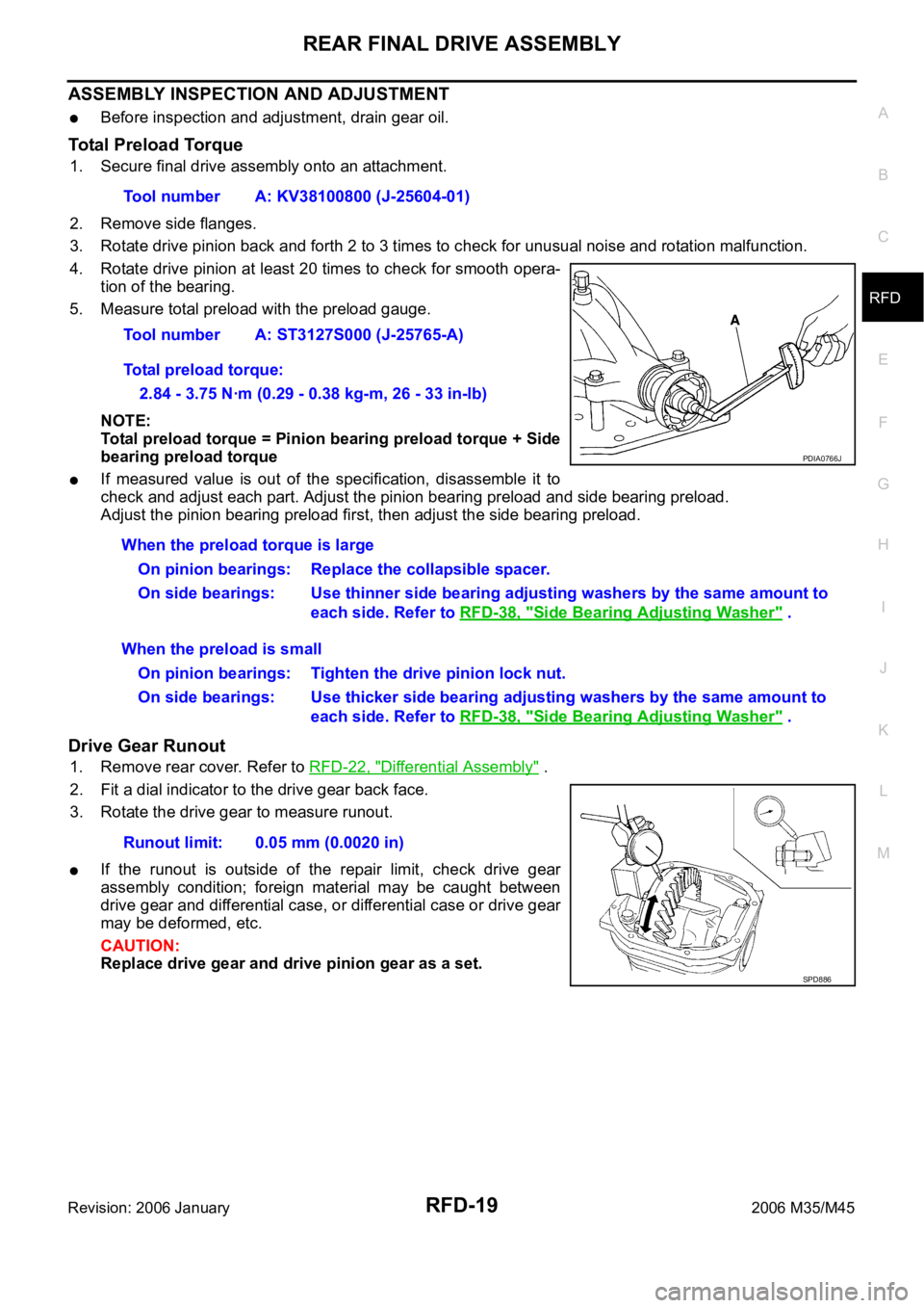
5. Measure total preload with the preload gauge.
NOTE:
Total preload torque = Pinion bearing preload torque + Side
bearing preload torque
If measured value is out of the specification, disassemble it to
check and adjust each part. Adjust the pinion bearing preload and side bearing preload.
Adjust the pinion bearing preload first, then adjust the side bearing preload.
Drive Gear Runout
1. Remove rear cover. Refer to RFD-22, "Differential Assembly" .
2. Fit a dial indicator to the drive gear back face.
3. Rotate the drive gear to measure runout.
If the runout is outside of the repair limit, check drive gear
assembly condition; foreign material may be caught between
drive gear and differential case, or differential case or drive gear
may be deformed, etc.
CAUTION:
Replace drive gear and drive pinion gear as a set.Tool number A: KV38100800 (J-25604-01)
Tool number A: ST3127S000 (J-25765-A)
Total preload torque:
2.84 - 3.75 Nꞏm (0.29 - 0.38 kg-m, 26 - 33 in-lb)
PDIA0766J
When the preload torque is large
On pinion bearings: Replace the collapsible spacer.
On side bearings: Use thinner side bearing adjusting washers by the same amount to
each side. Refer to RFD-38, "
Side Bearing Adjusting Washer" .
When the preload is small
On pinion bearings: Tighten the drive pinion lock nut.
On side bearings: Use thicker side bearing adjusting washers by the same amount to
each side. Refer to RFD-38, "
Side Bearing Adjusting Washer" .
Runout limit: 0.05 mm (0.0020 in)
SPD886
Page 5063 of 5621
RFD-20
REAR FINAL DRIVE ASSEMBLY
Revision: 2006 January2006 M35/M45
Tooth Contact
1. Remove rear cover. Refer to RFD-22, "Differential Assembly" .
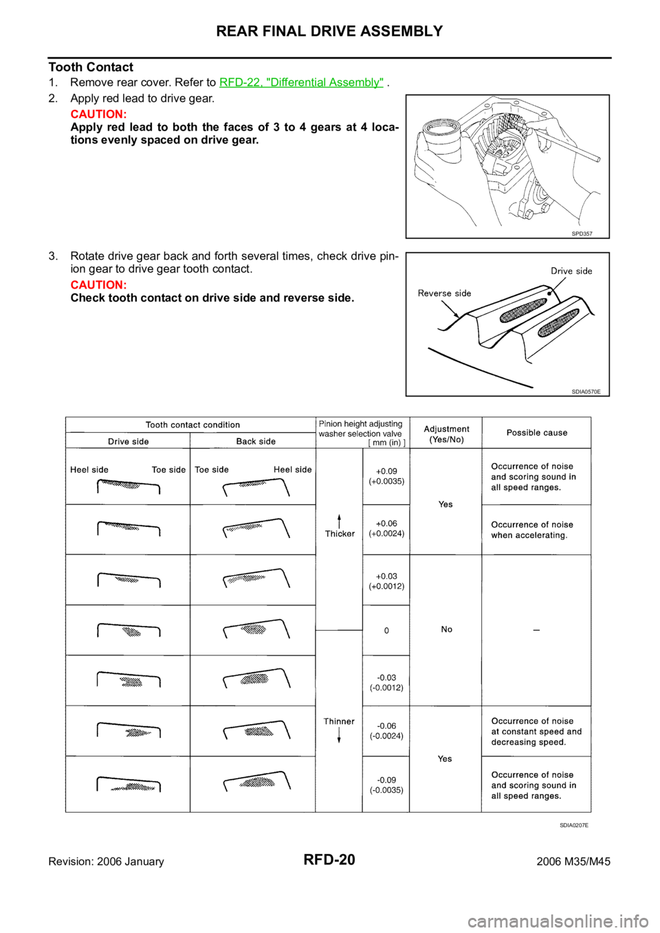
2. Apply red lead to drive gear.
CAUTION:
Apply red lead to both the faces of 3 to 4 gears at 4 loca-
tions evenly spaced on drive gear.
3. Rotate drive gear back and forth several times, check drive pin-
ion gear to drive gear tooth contact.
CAUTION:
Check tooth contact on drive side and reverse side.
SPD357
SDIA0570E
SDIA0207E
Page 5065 of 5621
RFD-22
REAR FINAL DRIVE ASSEMBLY
Revision: 2006 January2006 M35/M45
Companion Flange Runout
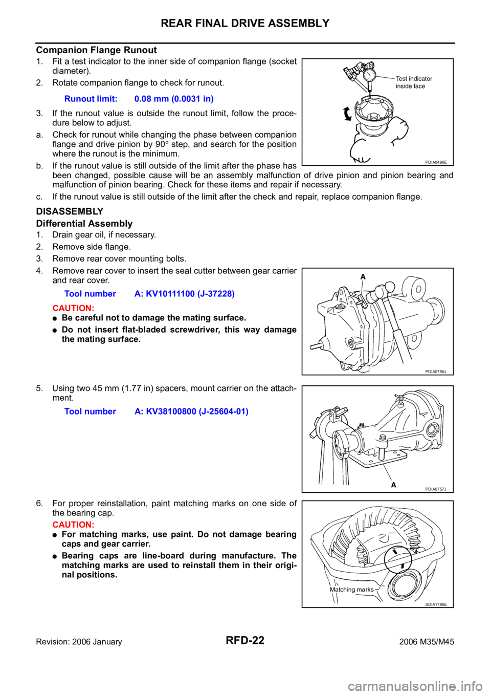
1. Fit a test indicator to the inner side of companion flange (socket
diameter).
2. Rotate companion flange to check for runout.
3. If the runout value is outside the runout limit, follow the proce-
dure below to adjust.
a. Check for runout while changing the phase between companion
flange and drive pinion by 90
step, and search for the position
where the runout is the minimum.
b. If the runout value is still outside of the limit after the phase has
been changed, possible cause will be an assembly malfunction of drive pinion and pinion bearing and
malfunction of pinion bearing. Check for these items and repair if necessary.
c. If the runout value is still outside of the limit after the check and repair, replace companion flange.
DISASSEMBLY
Differential Assembly
1. Drain gear oil, if necessary.
2. Remove side flange.
3. Remove rear cover mounting bolts.
4. Remove rear cover to insert the seal cutter between gear carrier
and rear cover.
CAUTION:
Be careful not to damage the mating surface.
Do not insert flat-bladed screwdriver, this way damage
the mating surface.
5. Using two 45 mm (1.77 in) spacers, mount carrier on the attach-
ment.
6. For proper reinstallation, paint matching marks on one side of
the bearing cap.
CAUTION:
For matching marks, use paint. Do not damage bearing
caps and gear carrier.
Bearing caps are line-board during manufacture. The
matching marks are used to reinstall them in their origi-
nal positions.Runout limit: 0.08 mm (0.0031 in)
PDIA0490E
Tool number A: KV10111100 (J-37228)
PDIA0756J
Tool number A: KV38100800 (J-25604-01)
PDIA0757J
SDIA1795E
Page 5076 of 5621
REAR FINAL DRIVE ASSEMBLY
RFD-33
C
E
F
G
H
I
J
K
L
MA
B
RFD
Revision: 2006 January2006 M35/M45
10. Apply anti-corrosion oil to the thread and seat of drive pinion
lock nut, and temporarily tighten drive pinion lock nut to drive
pinion.
CAUTION:
Do not reuse drive pinion lock nut.
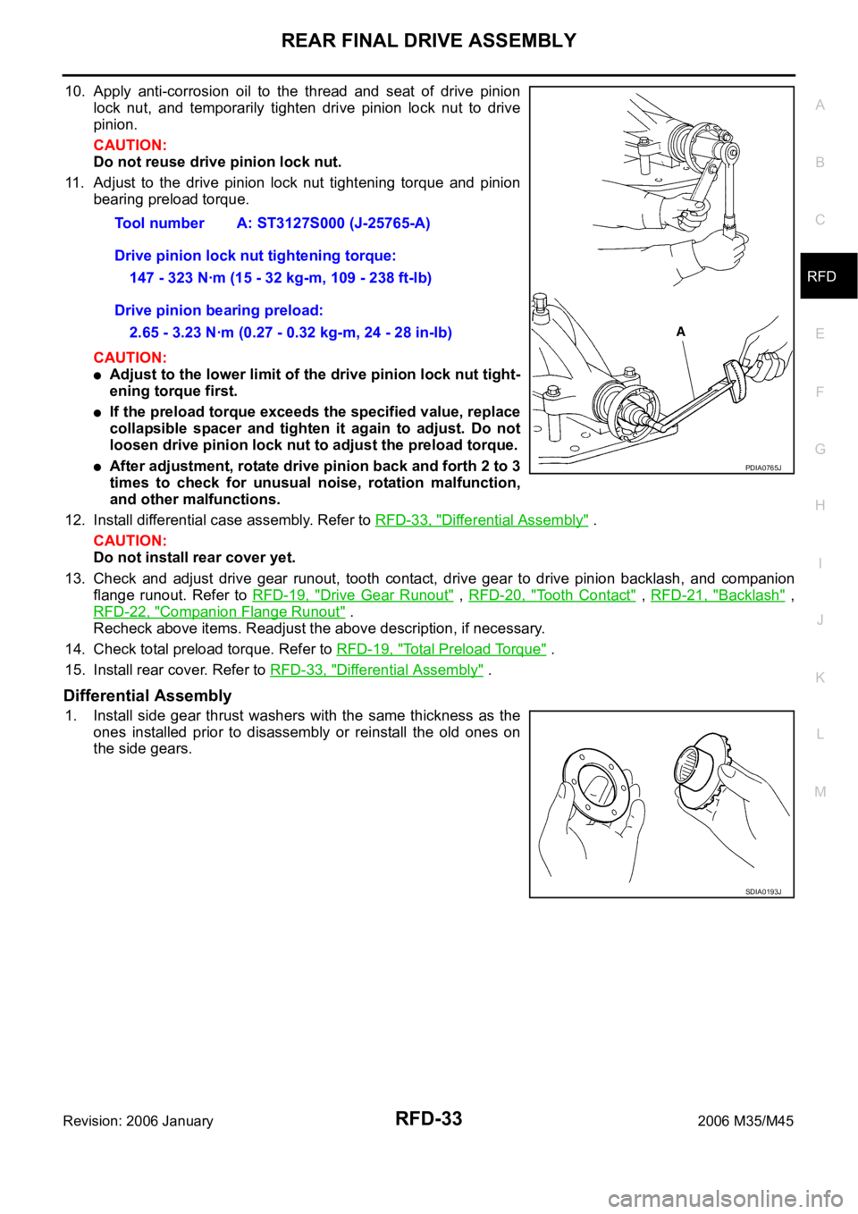
11. Adjust to the drive pinion lock nut tightening torque and pinion
bearing preload torque.
CAUTION:
Adjust to the lower limit of the drive pinion lock nut tight-
ening torque first.
If the preload torque exceeds the specified value, replace
collapsible spacer and tighten it again to adjust. Do not
loosen drive pinion lock nut to adjust the preload torque.
After adjustment, rotate drive pinion back and forth 2 to 3
times to check for unusual noise, rotation malfunction,
and other malfunctions.
12. Install differential case assembly. Refer to RFD-33, "
Differential Assembly" .
CAUTION:
Do not install rear cover yet.
13. Check and adjust drive gear runout, tooth contact, drive gear to drive pinion backlash, and companion
flange runout. Refer to RFD-19, "
Drive Gear Runout" , RFD-20, "Tooth Contact" , RFD-21, "Backlash" ,
RFD-22, "
Companion Flange Runout" .
Recheck above items. Readjust the above description, if necessary.
14. Check total preload torque. Refer to RFD-19, "
Total Preload Torque" .
15. Install rear cover. Refer to RFD-33, "
Differential Assembly" .
Differential Assembly
1. Install side gear thrust washers with the same thickness as the
ones installed prior to disassembly or reinstall the old ones on
the side gears.Tool number A: ST3127S000 (J-25765-A)
Drive pinion lock nut tightening torque:
147 - 323 Nꞏm (15 - 32 kg-m, 109 - 238 ft-lb)
Drive pinion bearing preload:
2.65 - 3.23 Nꞏm (0.27 - 0.32 kg-m, 24 - 28 in-lb)
PDIA0765J
SDIA0193J
Page 5079 of 5621
RFD-36
REAR FINAL DRIVE ASSEMBLY
Revision: 2006 January2006 M35/M45
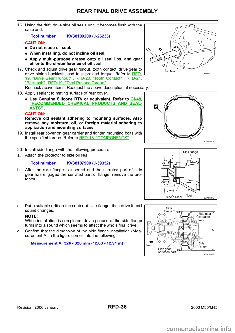
16. Using the drift, drive side oil seals until it becomes flush with the
case end.
CAUTION:
Do not reuse oil seal.
When installing, do not incline oil seal.
Apply multi-purpose grease onto oil seal lips, and gear
oil onto the circumference of oil seal.
17. Check and adjust drive gear runout, tooth contact, drive gear to
drive pinion backlash, and total preload torque. Refer to RFD-
19, "Drive Gear Runout" , RFD-20, "Tooth Contact" , RFD-21,
"Backlash" , RFD-19, "Total Preload Torque" .
Recheck above items. Readjust the above description, if necessary.
18. Apply sealant to mating surface of rear cover.
Use Genuine Silicone RTV or equivalent. Refer to GI-48,
"RECOMMENDED CHEMICAL PRODUCTS AND SEAL-
ANTS" .
CAUTION:
Remove old sealant adhering to mounting surfaces. Also
remove any moisture, oil, or foreign material adhering to
application and mounting surfaces.
19. Install rear cover on gear carrier and tighten mounting bolts with
the specified torque. Refer to RFD-18, "
COMPONENTS" .
20. Install side flange with the following procedure.
a. Attach the protector to side oil seal.
b. After the side flange is inserted and the serrated part of side
gear has engaged the serrated part of flange, remove the pro-
tector.
c. Put a suitable drift on the center of side flange, then drive it until
sound changes.
NOTE:
When installation is completed, driving sound of the side flange
turns into a sound which seems to affect the whole final drive.
d. Confirm that the dimension of the side flange installation (Mea-
surement A) in the figure comes into the following.Tool number : KV38100200 (J-26233)
SPD560
PDIA0961E
Tool number : KV38107900 (J-39352)
SDIA0822E
Measurement A: 326 - 328 mm (12.83 - 12.91 in)
SDIA1039E
Page 5081 of 5621

RFD-38
SERVICE DATA AND SPECIFICATIONS (SDS)
Revision: 2006 January2006 M35/M45
SELECTIVE PARTS
Side Gear Thrust Washer
Unit: mm (in)
*: Always check with the Parts Department for the latest parts information.
Pinion Height Adjusting Washer
Unit: mm (in)
*: Always check with the Parts Department for the latest parts information.
Side Bearing Adjusting Washer
Unit: mm (in)
*: Always check with the Parts Department for the latest parts information. Thickness Part number* Thickness Part number*
0.75 (0.0295)
0.78 (0.0307)
0.81 (0.0319)
0.84 (0.0331)38424 EC000
38424 EC001
38424 EC002
38424 EC0030.87 (0.0343)
0.90 (0.0350)
0.93 (0.0366)38424 EC004
38424 EC005
38424 EC006
Thickness Part number* Thickness Part number*
3.05 (0.1201)
3.08 (0.1213)
3.11 (0.1224)
3.14 (0.1236)38154 0C000
38154 0C001
38154 0C002
38154 0C0033.17 (0.1248)
3.20 (0.1260)
3.23 (0.1272)
3.26 (0.1283)38154 0C004
38154 0C005
38154 0C006
38154 0C007
Thickness Part number* Thickness Part number*
2.00 (0.0787)
2.05 (0.0807)
2.10 (0.0827)
2.15 (0.0846)
2.20 (0.0866)
2.25 (0.0886)
2.30 (0.0906)38453 N3100
38453 N3101
38453 N3102
38453 N3103
38453 N3104
38453 N3105
38453 N31062.35 (0.0925)
2.40 (0.0945)
2.45 (0.0965)
2.50 (0.0984)
2.55 (0.1004)
2.60 (0.1024)
2.65 (0.1043)38453 N3107
38453 N3108
38453 N3109
38453 N3110
38453 N3111
38453 N3112
38453 N3113
Page 5083 of 5621

RSU-2
PRECAUTIONS
Revision: 2006 January2006 M35/M45
PRECAUTIONSPFP:00001
PrecautionsNES000J2
When installing rubber bushings, final tightening must be carried out under unladen conditions with tires
on ground. Oil will shorten the life of rubber bushings. Be sure to wipe off any spilled oil.
–Unladen conditions mean that fuel, engine coolant and lubricant are full. Spare tire, jack, hand tools and
mats are in designated positions.
After servicing suspension parts, be sure to check wheel alignment.
Self-lock nuts are not reusable. Always use new ones when installing. Since new self-lock nuts are pre-
oiled, tighten as they are.
Page 5086 of 5621
REAR SUSPENSION ASSEMBLY
RSU-5
C
D
F
G
H
I
J
K
L
MA
B
RSU
Revision: 2006 January2006 M35/M45
REAR SUSPENSION ASSEMBLYPFP:55020
On-Vehicle Inspection and ServiceNES000J6
Make sure the mounting conditions (looseness, back lash) of each component and component conditions
(wear, damage) are normal.
SUSPENSION ARM BALL JOINT AXIAL END PLAY INSPECTION
Measure axial end play by placing and moving up/down with an iron pry bar or something similar between sus-
pension arm and axle.
CAUTION:
Be careful not to damage ball joint boot.
SHOCK ABSORBER INSPECTION
Check shock absorber for oil leakage, damage and replace if malfunction is detected.
Wheel Alignment InspectionNES000J7
DESCRIPTION
Measure wheel alignment under unladen conditions.
NOTE:
“Unladen conditions” means that fuel, engine coolant, and lubricant are full. Spare tire, jack, hand tools and
mats in designated positions.
PRELIMINARY INSPECTION
Check the following:
1. Tires for improper air pressure and wear.
2. Road wheels for runout. Refer to WT-6, "
ROAD WHEEL" .
3. Wheel bearing axial end play. Refer to RAX-5, "
WHEEL BEARING INSPECTION" .
4. Ball joint axial end play of suspension arm. Refer to RSU-5, "
SUSPENSION ARM BALL JOINT AXIAL
END PLAY INSPECTION" .
5. Shock absorber operation.
6. Each mounting point of axle and suspension for looseness and deformation.
7. Each of front lower link, rear lower link, radius rod, rear suspension member, suspension arm and shock
absorber for cracks, deformation, and other damage.
8. Vehicle height (posture).
GENERAL INFORMATION AND RECOMMENDATIONS
A four-wheel thrust alignment should be performed.
–This type of alignment is recommended for any NISSAN/INFINITI vehicle.
–The four-wheel “thrust” process helps ensure that the vehicle is properly aligned and the steering wheel is
centered.
–The alignment rack itself should be capable of accepting any NISSAN/INFINITI vehicle.
–The rack should be checked to ensure that it is level.
Make sure the machine is properly calibrated.
–Your alignment equipment should be regularly calibrated in order to give correct information.
–Check with the manufacturer of your specific equipment for their recommended Service/Calibration
Schedule.Standard value
Axial end play : 0 mm (0 in)