2006 INFINITI M35 brake rotor
[x] Cancel search: brake rotorPage 1344 of 5621
![INFINITI M35 2006 Factory Service Manual TROUBLE DIAGNOSIS
BRC-33
[VDC/TCS/ABS]
C
D
E
G
H
I
J
K
L
MA
B
BRC
Revision: 2006 January2006 M35/M45
Basic InspectionNFS000QK
BASIC INSPECTION 1: BRAKE FLUID LEVEL, LEAK INSPECTION AND BRAKE PAD
1. C INFINITI M35 2006 Factory Service Manual TROUBLE DIAGNOSIS
BRC-33
[VDC/TCS/ABS]
C
D
E
G
H
I
J
K
L
MA
B
BRC
Revision: 2006 January2006 M35/M45
Basic InspectionNFS000QK
BASIC INSPECTION 1: BRAKE FLUID LEVEL, LEAK INSPECTION AND BRAKE PAD
1. C](/manual-img/42/57023/w960_57023-1343.png)
TROUBLE DIAGNOSIS
BRC-33
[VDC/TCS/ABS]
C
D
E
G
H
I
J
K
L
MA
B
BRC
Revision: 2006 January2006 M35/M45
Basic InspectionNFS000QK
BASIC INSPECTION 1: BRAKE FLUID LEVEL, LEAK INSPECTION AND BRAKE PAD
1. Check fluid level in brake reservoir tank. If fluid level is low, refill brake fluid. Refer to BR-10, "CHECKING
BRAKE FLUID LEVEL" .
2. Check for leakage in brake tubes or hoses and around ABS actuator and electric unit (control unit). If
there is leaking or seeping fluid, check the following items.
If the brake tube connections at ABS actuator and electric unit (control unit) are loose, tighten flare nuts
to the specified torque. Then inspect again and confirm that there is no leakage.
If flare nuts or screws of ABS actuator and electric unit (control unit) are damaged and loose, replace
damaged parts. Then inspect again and confirm that there is no leakage.
If there is leakage at any location other than ABS actuator and electric unit (control unit) connections,
wipe away leakage with clean cloth. Then inspect again and confirm that there is no leakage.
If there is leakage from ABS actuator and electric unit (control unit), wipe away leakage with clean cloth.
Then inspect again. If there is still leakage, replace ABS actuator and electric unit (control unit).
CAUTION:
ABS actuator and electric unit (control unit) cannot be disassembled.
3. Check brake disc rotor and pads. Refer to BR-28, "
DISC ROTOR INSPECTION" (front disc rotor), BR-23,
"PAD WEAR INSPECTION" (front brake pad), BR-34, "DISC ROTOR INSPECTION" (rear disc rotor), BR-
29, "PAD WEAR INSPECTION" (rear brake pad).
BASIC INSPECTION 2: LOOSENESS OF POWER SYSTEM TERMINALS AND BATTERY
Check battery for looseness on battery positive/negative terminals and ground connection. Also make sure
battery voltage does not drop and alternator is normal.
BASIC INSPECTION 3: ABS WARNING LAMP, BRAKE WARNING LAMP, VDC OFF INDICATOR
LAMP AND SLIP INDICATOR LAMP
ON and OFF Timing for Warning Lamp and Indicator Lamp
: ON –: OFF
Note1: Brake warning lamp will turn on in case of parking brake operation (when switch is ON) or of brake fluid level switch operation
(when brake fluid is insufficient).
Note2: After starting engine, brake warning lamp is turned off.
Check the following items when unsuitable for an above condition.
ABS warning lamp: BRC-51, "Inspection 16: CAN Communication Circuit"
Brake warning lamp: BRC-51, "Inspection 16: CAN Communication Circuit" , BRC-48, "Inspection 12:
Brake Fluid Level Switch Circuit" , BRC-52, "Inspection 18: Parking Brake Switch Circuit"
VDC OFF indicator lamp:BRC-51, "Inspection 16: CAN Communication Circuit" , BRC-51, "Inspection 17:
VDC OFF Switch Circuit"
SLIP indicator lamp: BRC-51, "Inspection 16: CAN Communication Circuit"
If malfunction is not found, refer to BRC-53, "Inspection 19: Warning Lamp and Indicator Lamp Circuit" .
Condition ABS warning lampVDC OFF
indicator lampSLIP indicator lampBrake warning lamp
[Note1]
Ignition SW OFF – – – –
For 1 second after turning ON igni-
tion switch
[Note 2]
1 second later after turning ON
ignition switch–––
[Note 2]
VDC OFF switch turned ON. (VDC
function is OFF.)–
––
VDC/TCS function is malfunction-
ing.–
–
ABS function is malfunctioning.
–
EBD function is malfunctioning.
Page 1365 of 5621
![INFINITI M35 2006 Factory Service Manual BRC-54
[VDC/TCS/ABS]
TROUBLE DIAGNOSIS
Revision: 2006 January2006 M35/M45
2. CHECK FRONT AND REAR AXLE
Make sure that there is no excessive play in the front and rear axles. Refer to front: FAX-5, &# INFINITI M35 2006 Factory Service Manual BRC-54
[VDC/TCS/ABS]
TROUBLE DIAGNOSIS
Revision: 2006 January2006 M35/M45
2. CHECK FRONT AND REAR AXLE
Make sure that there is no excessive play in the front and rear axles. Refer to front: FAX-5, &#](/manual-img/42/57023/w960_57023-1364.png)
BRC-54
[VDC/TCS/ABS]
TROUBLE DIAGNOSIS
Revision: 2006 January2006 M35/M45
2. CHECK FRONT AND REAR AXLE
Make sure that there is no excessive play in the front and rear axles. Refer to front: FAX-5, "
WHEEL BEAR-
ING INSPECTION" , Rear: RAX-5, "WHEEL BEARING INSPECTION" .
OK or NG
OK >> GO TO 3.
NG >> Repair or replace malfunctioning components.
3. CHECK WHEEL SENSOR AND SENSOR ROTOR
Check the following.
Wheel sensor installation for damage.
Sensor rotor installation for damage.
Wheel sensor connector connection.
Wheel sensor harness inspection.
OK or NG
OK >> GO TO 4.
NG >>
Replace wheel sensor or sensor rotor.
Repair harness.
4. CHECK ABS WARNING LAMP DISPLAY
Make sure that the ABS warning lamp is turned off after the ignition switch is turned ON or when driving.
OK or NG
OK >> Normal
NG >> Perform self-diagnosis. Refer to BRC-23, "
Self-Diagnosis" .
Symptom 2 Unexpected Pedal ReactionNFS000R5
1. CHECK BRAKE PEDAL STROKE
Check brake pedal stroke. Refer to BR-6, "
Inspection and Adjustment" .
Is the stroke too big?
YES >>Bleed air from brake tube and hose. Refer to BR-11, "Bleeding Brake System" .
Check brake pedal, brake booster, and master cylinder for mount play, looseness, brake sys-
tem fluid leakage, etc. Refer to brake pedal: BR-7, "
COMPONENTS" , brake booster and mas-
ter cylinder: BR-19, "
COMPONENTS" .
NO >> GO TO 2.
2. CHECK FUNCTION
Disconnect ABS actuator and electric unit (control unit) connector to deactivate ABS. Check if braking force is
normal in this condition.Connect connector after inspection.
OK or NG
OK >> GO TO procedure 3 “CHECK WHEEL SENSOR AND SENSOR ROTOR” of symptom 1. Refer to
BRC-53, "
Symptom 1 Excessive ABS Function Operation Frequency" .
NG >> Check brake system.
Page 1366 of 5621
![INFINITI M35 2006 Factory Service Manual TROUBLE DIAGNOSIS
BRC-55
[VDC/TCS/ABS]
C
D
E
G
H
I
J
K
L
MA
B
BRC
Revision: 2006 January2006 M35/M45
Symptom 3 The Braking Distance Is LongNFS000R6
CAUTION:
The stopping distance on slippery road INFINITI M35 2006 Factory Service Manual TROUBLE DIAGNOSIS
BRC-55
[VDC/TCS/ABS]
C
D
E
G
H
I
J
K
L
MA
B
BRC
Revision: 2006 January2006 M35/M45
Symptom 3 The Braking Distance Is LongNFS000R6
CAUTION:
The stopping distance on slippery road](/manual-img/42/57023/w960_57023-1365.png)
TROUBLE DIAGNOSIS
BRC-55
[VDC/TCS/ABS]
C
D
E
G
H
I
J
K
L
MA
B
BRC
Revision: 2006 January2006 M35/M45
Symptom 3 The Braking Distance Is LongNFS000R6
CAUTION:
The stopping distance on slippery road surfaces might be longer with the ABS operating than when
the ABS is not operating.
1. CHECK FUNCTION
Turn ignition switch OFF and disconnect ABS actuator and electric unit (control unit) connector to deactivate
ABS. In this condition, check stopping distance. After inspection, connect connector.
OK or NG
OK >> GO TO procedure 3 “CHECK WHEEL SENSOR AND SENSOR ROTOR” of symptom 1. Refer to
BRC-53, "
Symptom 1 Excessive ABS Function Operation Frequency" .
NG >> Check brake system.
Symptom 4 ABS Function Does Not OperateNFS000R7
CAUTION:
ABS does not operate when speed is 10 km/h (6 MPH) or lower.
1. CHECK ABS WARNING LAMP DISPLAY
Make sure that the ABS warning lamp turns OFF after ignition switch is turned on or when driving.
OK or NG
OK >> GO TO procedure 3 “CHECK WHEEL SENSOR AND SENSOR ROTOR” of symptom 1. Refer to
BRC-53, "
Symptom 1 Excessive ABS Function Operation Frequency" .
NG >> Perform self-diagnosis. Refer to BRC-23, "
Self-Diagnosis" .
Symptom 5 Pedal Vibration or ABS Operation Sound OccursNFS000R8
CAUTION:
Under the following conditions, ABS is activated and vibration is felt when brake pedal is lightly
depressed (just place a foot on it).However, this is normal.
When shifting gears
When driving on slippery road
During cornering at high speed
When passing over bumps or grooves [at approximately 50 mm (1.97 in) or more]
When pulling away just after starting engine [at approximately 10 km/h (6 MPH) or higher]
1. SYMPTOM CHECK 1
Check if there is pedal vibration or operation sound when the engine is started.
Do symptoms occur?
YES >> GO TO 2.
NO >> Perform self -diagnosis. Refer to BRC-23, "
Self-Diagnosis" .
2. SYMPTOM CHECK 2
Check symptoms when electrical component (headlamps, etc.) switches are operated.
Do symptoms occur?
YES >> Check if there is a radio, antenna, antenna lead wire, or wiring close to the control unit. If there is,
move it farther away.
NO >> GO TO procedure 3 “CHECK WHEEL SENSOR AND SENSOR ROTOR” of symptom 1. Refer to
BRC-53, "
Symptom 1 Excessive ABS Function Operation Frequency" .
Page 3367 of 5621
FAX-8
FRONT DRIVE SHAFT
Revision: 2006 January2006 M35/M45
FRONT DRIVE SHAFTPFP:39100
On-Vehicle Inspection and ServiceNDS000FH
Check drive shaft mounting point and joint for looseness and other damage.
Check boot for cracks and other damage.
CAUTION:
Replace entire drive shaft assembly when noise or vibration occur from drive shaft.
DRIVE SHAFT BOOT REPLACEMENT
1. Remove tires from vehicle with a power tool.
2. Remove wheel sensor from steering knuckle. Refer to BRC-57, "
WHEEL SENSOR" .
CAUTION:
Do not pull on wheel sensor harness.
3. Remove brake hose bracket. Refer to BR-12, "
BRAKE TUBE AND HOSE" .
4. Remove torque menber fixing bolts with a power tool. Hang torque menber in a place where it will not
interfere with work. Refer to BR-23, "
FRONT DISC BRAKE" .
NOTE:
Do not depress brake pedal while brake caliper is removed.
5. Remove disc rotor. Refer to FA X - 5 , "
Removal and Installation" .
6. Remove cotter pin, then loosen hub lock nut with a power tool.
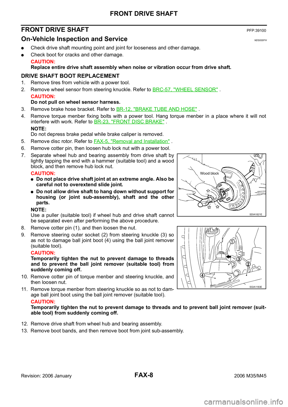
7. Separate wheel hub and bearing assembly from drive shaft by
lightly tapping the end with a hammer (suitable tool) and a wood
block, and then remove hub lock nut.
CAUTION:
Do not place drive shaft joint at an extreme angle. Also be
careful not to overextend slide joint.
Do not allow drive shaft to hang down without support for
housing (or joint sub-assembly), shaft and the other
parts.
NOTE:
Use a puller (suitable tool) if wheel hub and drive shaft cannot
be separated even after performing the above procedure.
8. Remove cotter pin (1), and then loosen the nut.
9. Remove steering outer socket (2) from steering knuckle (3) so
as not to damage ball joint boot (4) using the ball joint remover
(suitable tool).
CAUTION:
Temporarily tighten the nut to prevent damage to threads
and to prevent the ball joint remover (suitable tool) from
suddenly coming off.
10. Remove cotter pin of torque menber and steering knuckle, and
then loosen nut.
11. Remove torque menber from steering knuckle so as not to dam-
age ball joint boot using the ball joint remover (suitable tool).
CAUTION:
Temporarily tighten the nut to prevent damage to threads and to prevent ball joint remover (suit-
able tool) from suddenly coming off.
12. Remove drive shaft from wheel hub and bearing assembly.
13. Remove boot bands, and then remove boot from joint sub-assembly.
SDIA1821E
SGIA1183E
Page 3369 of 5621
FAX-10
FRONT DRIVE SHAFT
Revision: 2006 January2006 M35/M45
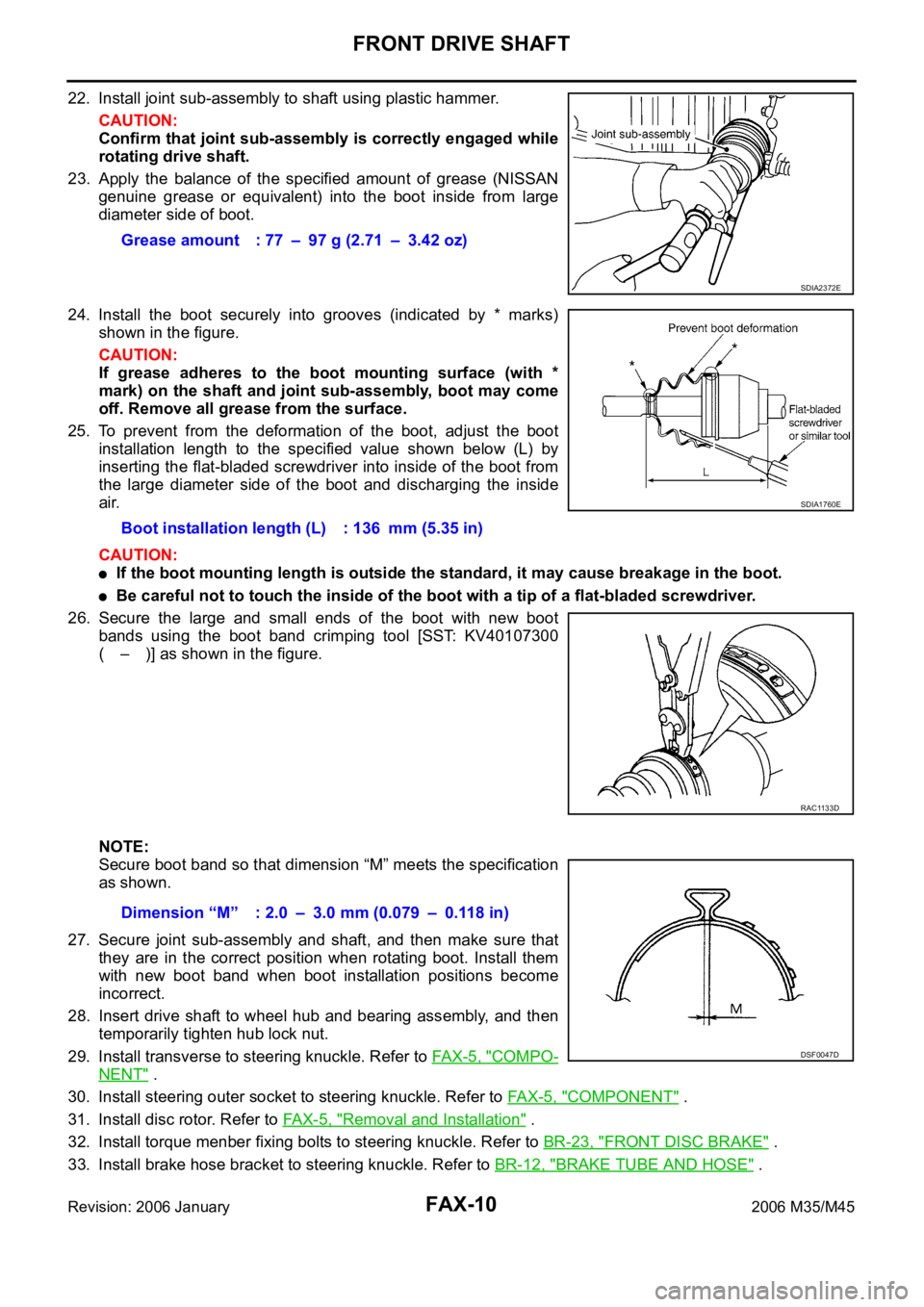
22. Install joint sub-assembly to shaft using plastic hammer.
CAUTION:
Confirm that joint sub-assembly is correctly engaged while
rotating drive shaft.
23. Apply the balance of the specified amount of grease (NISSAN
genuine grease or equivalent) into the boot inside from large
diameter side of boot.
24. Install the boot securely into grooves (indicated by * marks)
shown in the figure.
CAUTION:
If grease adheres to the boot mounting surface (with *
mark) on the shaft and joint sub-assembly, boot may come
off. Remove all grease from the surface.
25. To prevent from the deformation of the boot, adjust the boot
installation length to the specified value shown below (L) by
inserting the flat-bladed screwdriver into inside of the boot from
the large diameter side of the boot and discharging the inside
air.
CAUTION:
If the boot mounting length is outside the standard, it may cause breakage in the boot.
Be careful not to touch the inside of the boot with a tip of a flat-bladed screwdriver.
26. Secure the large and small ends of the boot with new boot
bands using the boot band crimping tool [SST: KV40107300
( – )] as shown in the figure.
NOTE:
Secure boot band so that dimension “M” meets the specification
as shown.
27. Secure joint sub-assembly and shaft, and then make sure that
they are in the correct position when rotating boot. Install them
with new boot band when boot installation positions become
incorrect.
28. Insert drive shaft to wheel hub and bearing assembly, and then
temporarily tighten hub lock nut.
29. Install transverse to steering knuckle. Refer to FAX-5, "
COMPO-
NENT" .
30. Install steering outer socket to steering knuckle. Refer to FA X - 5 , "
COMPONENT" .
31. Install disc rotor. Refer to FA X - 5 , "
Removal and Installation" .
32. Install torque menber fixing bolts to steering knuckle. Refer to BR-23, "
FRONT DISC BRAKE" .
33. Install brake hose bracket to steering knuckle. Refer to BR-12, "
BRAKE TUBE AND HOSE" . Grease amount : 77 – 97 g (2.71 – 3.42 oz)
SDIA2372E
Boot installation length (L) : 136 mm (5.35 in)
SDIA1760E
RAC1133D
Dimension “M” : 2.0 – 3.0 mm (0.079 – 0.118 in)
DSF0047D
Page 3370 of 5621
FRONT DRIVE SHAFT
FAX-11
C
E
F
G
H
I
J
K
L
MA
B
FA X
Revision: 2006 January2006 M35/M45
34. Install wheel sensor to steering knuckle. Refer to BRC-57, "WHEEL SENSOR" .
35. Tighten the hub lock nut to the specified torque. Refer to FA X - 5 , "
COMPONENT" .
36. Install cotter pin.
37. Install tires to vehicle.
Removal and InstallationNDS000FI
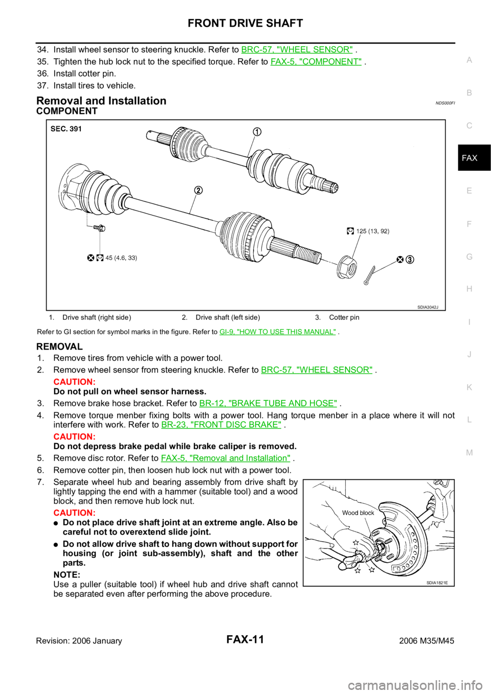
COMPONENT
Refer to GI section for symbol marks in the figure. Refer to GI-9, "HOW TO USE THIS MANUAL" .
REMOVAL
1. Remove tires from vehicle with a power tool.
2. Remove wheel sensor from steering knuckle. Refer to BRC-57, "
WHEEL SENSOR" .
CAUTION:
Do not pull on wheel sensor harness.
3. Remove brake hose bracket. Refer to BR-12, "
BRAKE TUBE AND HOSE" .
4. Remove torque menber fixing bolts with a power tool. Hang torque menber in a place where it will not
interfere with work. Refer to BR-23, "
FRONT DISC BRAKE" .
CAUTION:
Do not depress brake pedal while brake caliper is removed.
5. Remove disc rotor. Refer to FAX-5, "
Removal and Installation" .
6. Remove cotter pin, then loosen hub lock nut with a power tool.
7. Separate wheel hub and bearing assembly from drive shaft by
lightly tapping the end with a hammer (suitable tool) and a wood
block, and then remove hub lock nut.
CAUTION:
Do not place drive shaft joint at an extreme angle. Also be
careful not to overextend slide joint.
Do not allow drive shaft to hang down without support for
housing (or joint sub-assembly), shaft and the other
parts.
NOTE:
Use a puller (suitable tool) if wheel hub and drive shaft cannot
be separated even after performing the above procedure.
1. Drive shaft (right side) 2. Drive shaft (left side) 3. Cotter pin
SDIA3042J
SDIA1821E
Page 4786 of 5621
PERIODIC MAINTENANCE
MA-9
C
D
E
F
G
H
I
J
K
MA
B
MA
Revision: 2006 January2006 M35/M45
NOTE:
(1) After 60,000 miles (96,000 km) or 48 months, inspect every 15,000 miles (24,000 km) or 12 months. Replace the drive belts if found
damaged or if the auto belt tensioner reading (only for VK45DE engine) reaches the maximum limit.
(2) If operating mainly in dusty conditions, more frequent maintenance may be required.
(3) Maintenance-free item. For service procedures, refer to FL section.
(4) After 60,000 miles (96,000 km) or 48 months, replace every 30,000 miles (48,000 km) or 24 months.
(5) If valve noise increases, inspect valve clearance.
* Maintenance items and intervals with “*” are recommended by INFINITI for reliable vehicle operation. The owner need not perform
such maintenance in order to maintain the emission warranty or manufacturer recall liability. Other maintenance items and intervals are
required.
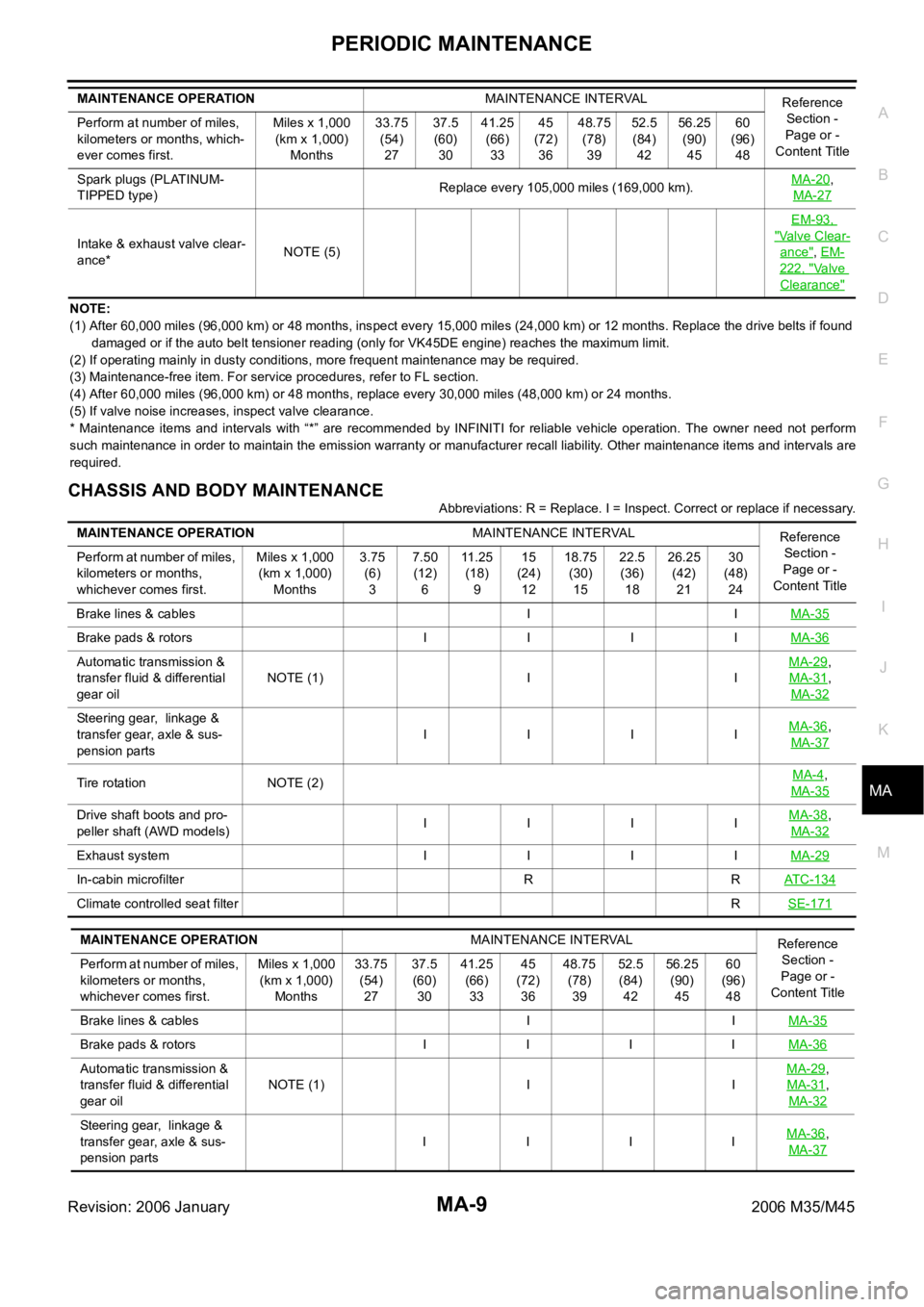
CHASSIS AND BODY MAINTENANCE
Abbreviations: R = Replace. I = Inspect. Correct or replace if necessary. Spark plugs (PLATINUM-
TIPPED type)Replace every 105,000 miles (169,000 km).MA-20
,
MA-27
Intake & exhaust valve clear-
ance*NOTE (5)EM-93, "Valve Clear-
ance", EM-
222, "Va l v e
Clearance"
MAINTENANCE OPERATIONMAINTENANCE INTERVAL
Reference
Section -
Page or -
Content Title Perform at number of miles,
kilometers or months, which-
ever comes first.Miles x 1,000
(km x 1,000)
Months33.75
(54)
2737.5
(60)
3041.25
(66)
3345
(72)
3648.75
(78)
3952.5
(84)
4256.25
(90)
4560
(96)
48
MAINTENANCE OPERATIONMAINTENANCE INTERVAL
Reference
Section -
Page or -
Content Title Perform at number of miles,
kilometers or months,
whichever comes first.Miles x 1,000
(km x 1,000)
Months3.75
(6)
37.50
(12)
611 . 2 5
(18)
915
(24)
1218.75
(30)
1522.5
(36)
1826.25
(42)
2130
(48)
24
Brake lines & cables I IMA-35
Brake pads & rotors I I I IMA-36
Automatic transmission &
transfer fluid & differential
gear oilNOTE (1) I IMA-29,
MA-31
,
MA-32
Steering gear, linkage &
transfer gear, axle & sus-
pension partsIIIIMA-36,
MA-37
Tire rotation NOTE (2)MA-4,
MA-35
Drive shaft boots and pro-
peller shaft (AWD models) IIIIMA-38,
MA-32
Exhaust system I I I IMA-29
In-cabin microfilter R RAT C - 1 3 4
Climate controlled seat filterRSE-171
MAINTENANCE OPERATIONMAINTENANCE INTERVAL
Reference
Section -
Page or -
Content Title Perform at number of miles,
kilometers or months,
whichever comes first.Miles x 1,000
(km x 1,000)
Months33.75
(54)
2737.5
(60)
3041.25
(66)
3345
(72)
3648.75
(78)
3952.5
(84)
4256.25
(90)
4560
(96)
48
Brake lines & cables I IMA-35
Brake pads & rotors I I I IMA-36
Automatic transmission &
transfer fluid & differential
gear oilNOTE (1) I IMA-29,
MA-31
,
MA-32
Steering gear, linkage &
transfer gear, axle & sus-
pension partsI IIIMA-36,
MA-37
Page 4788 of 5621
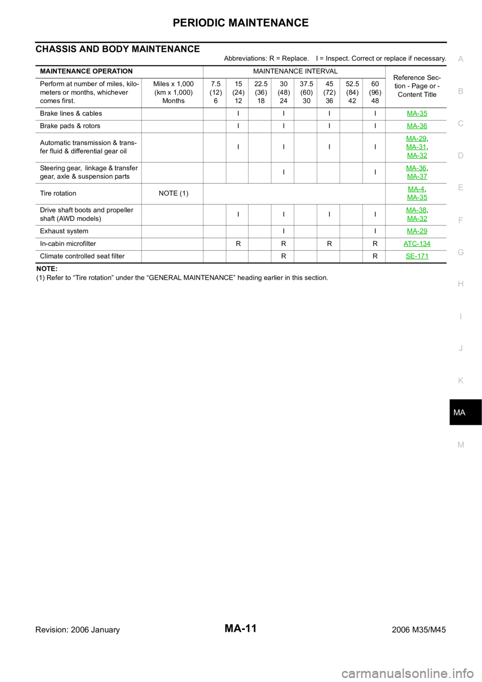
PERIODIC MAINTENANCE
MA-11
C
D
E
F
G
H
I
J
K
MA
B
MA
Revision: 2006 January2006 M35/M45
CHASSIS AND BODY MAINTENANCE
Abbreviations: R = Replace. I = Inspect. Correct or replace if necessary.
NOTE:
(1) Refer to “Tire rotation” under the “GENERAL MAINTENANCE” heading earlier in this section. MAINTENANCE OPERATIONMAINTENANCE INTERVAL
Reference Sec-
tion - Page or -
Content Title Perform at number of miles, kilo-
meters or months, whichever
comes first.Miles x 1,000
(km x 1,000)
Months7.5
(12)
615
(24)
1222.5
(36)
1830
(48)
2437.5
(60)
3045
(72)
3652.5
(84)
4260
(96)
48
Brake lines & cables I I I IMA-35
Brake pads & rotors I I I IMA-36
Automatic transmission & trans-
fer fluid & differential gear oilIIIIMA-29,
MA-31
,
MA-32
Steering gear, linkage & transfer
gear, axle & suspension partsIIMA-36,
MA-37
Tire rotation NOTE (1)MA-4,
MA-35
Drive shaft boots and propeller
shaft (AWD models) IIIIMA-38,
MA-32
Exhaust system I IMA-29
In-cabin microfilter R R R RATC-134
Climate controlled seat filter R RSE-171