2006 INFINITI M35 wheel
[x] Cancel search: wheelPage 3378 of 5621

FFD-1
FRONT FINAL DRIVE
D DRIVELINE/AXLE
CONTENTS
C
E
F
G
H
I
J
K
L
M
SECTION FFD
A
B
FFD
Revision: 2006 January2006 M35/M45
FRONT FINAL DRIVE
PRECAUTIONS .......................................................... 2
Precautions Necessary for Steering Wheel Rotation
after Battery Disconnect ........................................... 2
OPERATION PROCEDURE ................................. 2
Service Notice or Precautions .................................. 2
PREPARATION ........................................................... 3
Special Service Tools ............................................... 3
Commercial Service Tools ........................................ 5
NOISE, VIBRATION AND HARSHNESS (NVH)
TROUBLESHOOTING ................................................ 6
NVH Troubleshooting Chart ..................................... 6
DESCRIPTION ............................................................ 7
Cross-Sectional View ............................................... 7
DIFFERENTIAL GEAR OIL ........................................ 8
Changing Differential Gear Oil ................................. 8
DRAINING ............................................................. 8
FILLING ................................................................. 8
Checking Differential Gear Oil .................................. 8
OIL LEAKAGE AND OIL LEVEL ........................... 8
FRONT OIL SEAL .................................................
..... 9
Removal and Installation .......................................... 9
REMOVAL ........................................................
..... 9
INSTALLATION ................................................... 10SIDE OIL SEAL ......................................................... 11
Removal and Installation ........................................ 11
REMOVAL ........................................................
... 11
INSTALLATION ................................................... 11
FRONT FINAL DRIVE ASSEMBLY .......................... 13
Removal and Installation ........................................ 13
COMPONENTS ................................................... 13
REMOVAL ........................................................
... 13
INSTALLATION ................................................... 14
Disassembly and Assembly .................................... 15
COMPONENTS ................................................... 15
ASSEMBLY INSPECTION AND ADJUSTMENT ... 16
DISASSEMBLY ................................................... 20
INSPECTION AFTER DISASSEMBLY ................ 24
ADJUSTMENT AND SELECTION OF ADJUST-
ING WASHERS (SHIMS) .................................... 25
ASSEMBLY ......................................................... 28
SERVICE DATA AND SPECIFICATIONS (SDS) ...... 35
General Specifications ......................................... ... 35
Inspection and Adjustment ..................................... 35
DRIVE GEAR RUNOUT ...................................... 35
DIFFERENTIAL SIDE GEAR CLEARANCE ....... 35
PRELOAD TORQUE ........................................... 35
BACKLASH ......................................................... 35
COMPANION FLANGE RUNOUT ....................... 35
SELECTIVE PARTS ............................................ 35
Page 3379 of 5621

FFD-2
PRECAUTIONS
Revision: 2006 January2006 M35/M45
PRECAUTIONSPFP:00001
Precautions Necessary for Steering Wheel Rotation after Battery DisconnectNDS000EK
NOTE:
Before removing and installing any control units, first turn the push-button ignition switch to the LOCK
position, then disconnect both battery cables.
After finishing work, confirm that all control unit connectors are connected properly, then re-connect both
battery cables.
Always use CONSULT-II to perform self-diagnosis as a part of each function inspection after finishing
work. If a DTC is detected, perform trouble diagnosis according to self-diagnosis results.
This vehicle is equipped with a push-button ignition switch and a steering lock unit.
If the battery is disconnected or discharged, the steering wheel will lock and cannot be turned.
If turning the steering wheel is required with the battery disconnected or discharged, follow the procedure
below before starting the repair operation.
OPERATION PROCEDURE
1. Connect both battery cables.
NOTE:
Supply power using jumper cables if battery is discharged.
2. Carry the Intelligent Key or insert it to the key slot and turn the push-button ignition switch to ACC position.
(At this time, the steering lock will be released.)
3. Disconnect both battery cables. The steering lock will remain released with both battery cables discon-
nected and the steering wheel can be turned.
4. Perform the necessary repair operation.
5. When the repair work is completed, re-connect both battery cables. With the brake pedal released, turn
the push-button ignition switch from ACC position to ON position, then to LOCK position. (The steering
wheel will lock when the push-button ignition switch is turned to LOCK position.)
6. Perform self-diagnosis check of all control units using CONSULT-II.
Service Notice or PrecautionsNDS000EL
Check for the correct installation status prior to removal or disassembly. If matching marks are required,
be certain they do not interfere with the function of the parts when applied.
Overhaul should be done in a clean work area, it is preferable to work in dustproof area.
Before disassembly, using steam or white gasoline, completely remove sand and mud from the exterior of
the unit, preventing them from entering into the unit during disassembly or assembly.
Check appearance of the disassembled parts for damage, deformation, and unusual wear. Replace them
with a new ones if necessary.
Gaskets, seals and O-rings should be replaced any time when the unit is disassembled.
In principle, tighten bolts or nuts gradually in several steps working diagonally from inside to outside. If
tightening sequence is specified, observe it.
Clean and flush the parts sufficiently and blow-dry them.
Be careful not to damage sliding surfaces and mating surfaces.
When applying sealant, remove the old sealant from the mounting surface; then remove any moisture, oil,
and foreign materials from the application and mounting surfaces.
Always use shop paper for cleaning the inside of components.
Avoid using cotton gloves or shop rags to prevent entering of lint.
During assembly, observe the specified tightening torque, and apply new gear oil, petroleum jelly, or multi-
purpose grease as specified for each vehicle, if necessary.
Page 3383 of 5621

FFD-6
NOISE, VIBRATION AND HARSHNESS (NVH) TROUBLESHOOTING
Revision: 2006 January2006 M35/M45
NOISE, VIBRATION AND HARSHNESS (NVH) TROUBLESHOOTINGPFP:00003
NVH Troubleshooting ChartNDS000EO
Use the chart below to help you find the cause of the symptom. If necessary, repair or replace these parts.
: ApplicableReference page
Refer to FFD-24, "
INSPECTION AFTER DISASSEMBLY
" .
Refer to FFD-17, "
Tooth Contact
" .
Refer to FFD-24, "
INSPECTION AFTER DISASSEMBLY
" .
Refer to FFD-19, "
Backlash
" .
Refer to FFD-19, "
Companion Flange Runout
" .
Refer to FFD-8, "
Checking Differential Gear Oil
" .
NVH in PR section.
NVH in FAX, RAX, FSU and RSU sections.
NVH in WT section.
NVH in WT section.
NVH in FAX and RAX section.
NVH in BR section.
NVH in PS section.
Possible cause and SUSPECTED PARTS
Gear tooth rough
Gear contact improper
Tooth surfaces worn
Backlash incorrect
Companion flange excessive runout
Gear oil improper
PROPELLER SHAFT
AXLE AND SUSPENSION
TIRES
ROAD WHEEL
DRIVE SHAFT
BRAKES
STEERING
Symptom Noise
Page 3425 of 5621

FL-12
FUEL TANK
Revision: 2006 January2006 M35/M45
2. Start engine and rev it up and make sure there are no fuel leaks at the fuel system tube and hose connec-
tions.
After removing/installing rear suspension assembly, make sure to adjust wheel alignment and then, adjust
neutral position of steering angle sensor. Refer to RSU-5, "
Wheel Alignment Inspection" and BRC-6,
"Adjustment of Steering Angle Sensor Neutral Position" .
Page 3428 of 5621

FSU-1
FRONT SUSPENSION
E SUSPENSION
CONTENTS
C
D
F
G
H
I
J
K
L
M
SECTION FSU
A
B
FSU
Revision: 2006 January2006 M35/M45
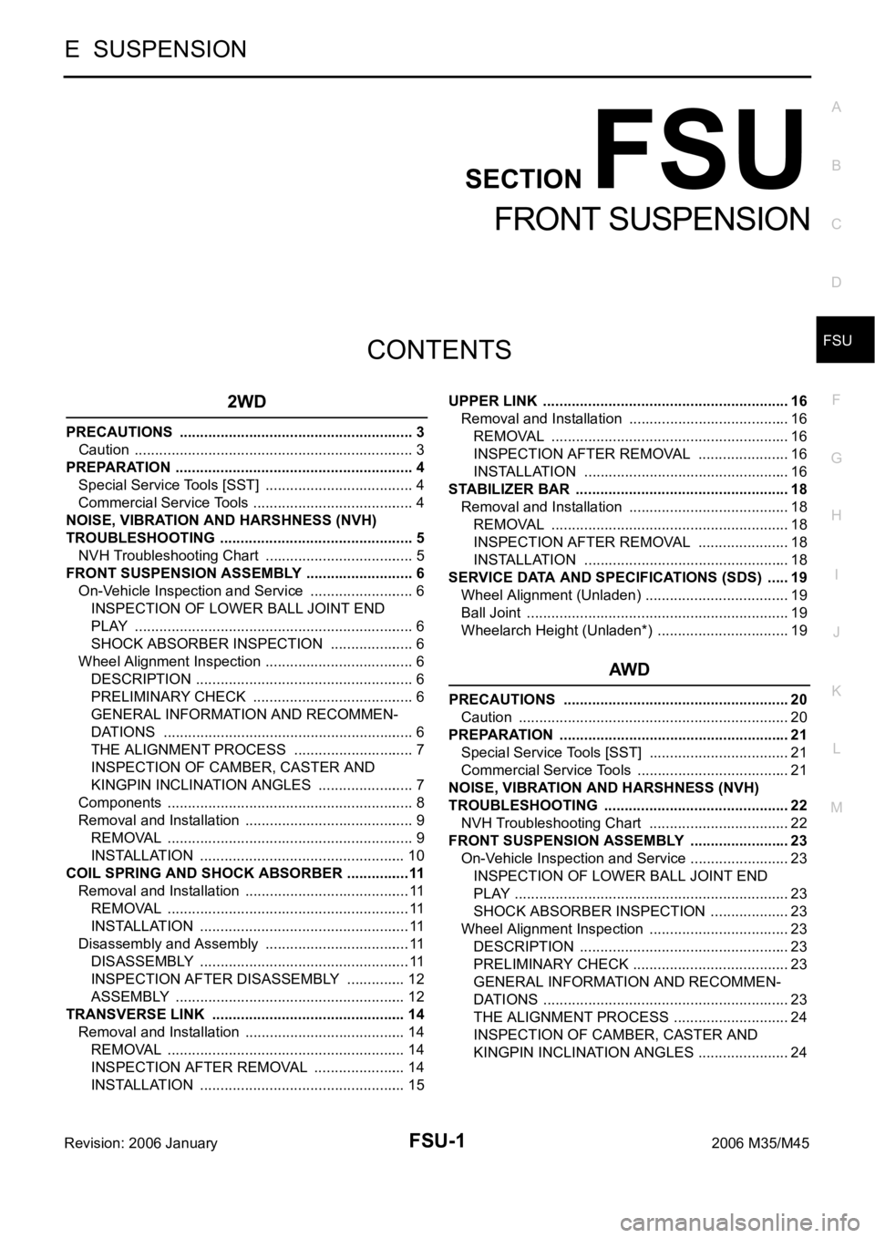
FRONT SUSPENSION
2WD
PRECAUTIONS .......................................................... 3
Caution ..................................................................... 3
PREPARATION ........................................................... 4
Special Service Tools [SST] ..................................... 4
Commercial Service Tools ........................................ 4
NOISE, VIBRATION AND HARSHNESS (NVH)
TROUBLESHOOTING ................................................ 5
NVH Troubleshooting Chart ..................................... 5
FRONT SUSPENSION ASSEMBLY ........................... 6
On-Vehicle Inspection and Service .......................... 6
INSPECTION OF LOWER BALL JOINT END
PLAY ..................................................................... 6
SHOCK ABSORBER INSPECTION ..................... 6
Wheel Alignment Inspection ..................................... 6
DESCRIPTION ...................................................... 6
PRELIMINARY CHECK ........................................ 6
GENERAL INFORMATION AND RECOMMEN-
DATIONS .............................................................. 6
THE ALIGNMENT PROCESS .............................. 7
INSPECTION OF CAMBER, CASTER AND
KINGPIN INCLINATION ANGLES ........................ 7
Components ............................................................. 8
Removal and Installation .......................................... 9
REMOVAL ........................................................
..... 9
INSTALLATION ................................................... 10
COIL SPRING AND SHOCK ABSORBER ................11
Removal and Installation ......................................... 11
REMOVAL ........................................................
.... 11
INSTALLATION .................................................... 11
Disassembly and Assembly .................................... 11
DISASSEMBLY .................................................... 11
INSPECTION AFTER DISASSEMBLY ............... 12
ASSEMBLY ......................................................... 12
TRANSVERSE LINK ................................................ 14
Removal and Installation ........................................ 14
REMOVAL ........................................................
... 14
INSPECTION AFTER REMOVAL ....................... 14
INSTALLATION ................................................... 15UPPER LINK ............................................................. 16
Removal and Installation ........................................ 16
REMOVAL ........................................................
... 16
INSPECTION AFTER REMOVAL ....................... 16
INSTALLATION ................................................... 16
STABILIZER BAR ..................................................... 18
Removal and Installation ........................................ 18
REMOVAL ........................................................
... 18
INSPECTION AFTER REMOVAL ....................... 18
INSTALLATION ................................................... 18
SERVICE DATA AND SPECIFICATIONS (SDS) ...... 19
Wheel Alignment (Unladen) .................................... 19
Ball Joint ....................................................
............. 19
Wheelarch Height (Unladen*) ................................. 19
AWD
PRECAUTIONS ........................................................ 20
Caution ................................................................... 20
PREPARATION ......................................................... 21
Special Service Tools [SST] ................................... 21
Commercial Service Tools ...................................... 21
NOISE, VIBRATION AND HARSHNESS (NVH)
TROUBLESHOOTING .............................................. 22
NVH Troubleshooting Chart ................................... 22
FRONT SUSPENSION ASSEMBLY ......................... 23
On-Vehicle Inspection and Service ......................... 23
INSPECTION OF LOWER BALL JOINT END
PLAY .................................................................... 23
SHOCK ABSORBER INSPECTION .................... 23
Wheel Alignment Inspection ................................... 23
DESCRIPTION .................................................... 23
PRELIMINARY CHECK ....................................... 23
GENERAL INFORMATION AND RECOMMEN-
DATIONS ............................................................. 23
THE ALIGNMENT PROCESS ............................. 24
INSPECTION OF CAMBER, CASTER AND
KINGPIN INCLINATION ANGLES ....................... 24
Page 3429 of 5621

FSU-2Revision: 2006 January2006 M35/M45 Components ........................................................... 25
Removal and Installation ........................................ 26
REMOVAL ........................................................
... 26
INSTALLATION .................................................... 26
COIL SPRING AND SHOCK ABSORBER ............... 28
Removal and Installation ........................................ 28
REMOVAL ........................................................
... 28
INSTALLATION .................................................... 28
Disassembly and Assembly .................................... 28
DISASSEMBLY ................................................... 28
INSPECTION AFTER DISASSEMBLY ................ 29
ASSEMBLY ......................................................... 29
TRANSVERSE LINK ................................................. 31
Removal and Installation ........................................ 31
REMOVAL ........................................................
... 31
INSPECTION AFTER REMOVAL ........................ 31
INSTALLATION .................................................... 32UPPER LINK ............................................................. 33
Removal and Installation ......................................... 33
REMOVAL ............................................................ 33
INSPECTION AFTER REMOVAL ........................ 33
INSTALLATION .................................................... 33
STABILIZER BAR ..................................................... 35
Removal and Installation ......................................... 35
REMOVAL ............................................................ 35
INSPECTION AFTER REMOVAL ........................ 35
INSTALLATION .................................................... 35
SERVICE DATA AND SPECIFICATIONS (SDS) ...... 36
Wheel Alignment (Unladen) .................................... 36
Ball Joint ................................................................. 36
Wheelarch Height (Unladen*) ................................. 36
Page 3430 of 5621
![INFINITI M35 2006 Factory Service Manual PRECAUTIONS
FSU-3
[2WD]
C
D
F
G
H
I
J
K
L
MA
B
FSU
Revision: 2006 January2006 M35/M45
[2WD]PRECAUTIONSPFP:00001
CautionNES000I6
When installing rubber bushings, the final tightening must be c INFINITI M35 2006 Factory Service Manual PRECAUTIONS
FSU-3
[2WD]
C
D
F
G
H
I
J
K
L
MA
B
FSU
Revision: 2006 January2006 M35/M45
[2WD]PRECAUTIONSPFP:00001
CautionNES000I6
When installing rubber bushings, the final tightening must be c](/manual-img/42/57023/w960_57023-3429.png)
PRECAUTIONS
FSU-3
[2WD]
C
D
F
G
H
I
J
K
L
MA
B
FSU
Revision: 2006 January2006 M35/M45
[2WD]PRECAUTIONSPFP:00001
CautionNES000I6
When installing rubber bushings, the final tightening must be carried out under unladen conditions with
tires on ground. Oil might shorten the life of rubber bushings. Be sure to wipe off any spilled oil.
–Unladen conditions mean that fuel, engine coolant and lubricant are full. Spare tire, jack, hand tools and
mats are in designated positions.
After servicing suspension parts, be sure to check wheel alignment.
Self-lock nuts are not reusable. Always use new ones when installing. Since new self-lock nuts are pre-
oiled, tighten as they are.
Page 3431 of 5621
![INFINITI M35 2006 Factory Service Manual FSU-4
[2WD]
PREPARATION
Revision: 2006 January2006 M35/M45
PREPARATIONPFP:00002
Special Service Tools [SST]NES000I7
The actual shapes of Kent-Moore tools may differ from those of special service tools INFINITI M35 2006 Factory Service Manual FSU-4
[2WD]
PREPARATION
Revision: 2006 January2006 M35/M45
PREPARATIONPFP:00002
Special Service Tools [SST]NES000I7
The actual shapes of Kent-Moore tools may differ from those of special service tools](/manual-img/42/57023/w960_57023-3430.png)
FSU-4
[2WD]
PREPARATION
Revision: 2006 January2006 M35/M45
PREPARATIONPFP:00002
Special Service Tools [SST]NES000I7
The actual shapes of Kent-Moore tools may differ from those of special service tools illustrated here.
Commercial Service ToolsNES000I8
Tool number
(Kent-Moore No.)
Tool nameDescription
KV991040S0
(—)
CCK gauge attachment
1. Plate
2. Guide bolt
3. Nut
4. Spring
5. Center plate
6. KV99104020 Adapter A
a: 72 mm (2.83 in) dia.
7. KV99104030 Adapter B
b: 65 mm (2.56 in) dia.
8. KV99104040 Adapter C
c: 57 mm (2.24 in) dia.
9. KV99104050 Adapter D
d: 53.4 mm (2.102 in) dia.Measuring wheel alignment
ST35652000
(—)
Strut attachmentDisassembling and assembling shock
absorber
ST3127S000
(See J-25765-A)
Preload Gauge
1. GG91030000
(J-25765-A)
Torque wrench
2. HT62940000
(—)
Socket adapter
3. HT62900000
(—)
Socket adapterMeasuring rotating torque of ball joint
S-NT498
ZZA0807D
NT124
Tool nameDescription
Power tool
Removing wheel nuts
Removing torque member fixing bolts
Removing undercover
Removing front suspension compo-
nents parts
Removing hub lock nut
Spring compressor Removing and installing coil springPBIC0190E
S-NT717