2006 INFINITI M35 battery replacement
[x] Cancel search: battery replacementPage 1210 of 5621
IVIS (INFINITI VEHICLE IMMOBILIZER SYSTEM-NATS)
BL-271
C
D
E
F
G
H
J
K
L
MA
B
BL
Revision: 2006 January2006 M35/M45
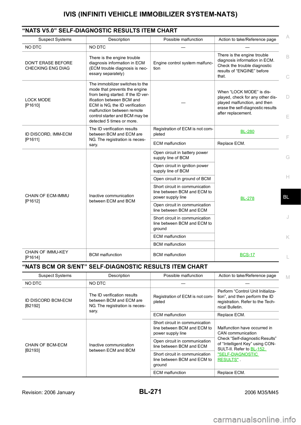
“NATS V5.0” SELF-DIAGNOSTIC RESULTS ITEM CHART
“NATS BCM OR S/ENT” SELF-DIAGNOSTIC RESULTS ITEM CHART
Suspect Systems Description Possible malfunction Action to take/Reference page
NO DTC NO DTC — —
DON'T ERASE BEFORE
CHECKING ENG DIAGThere is the engine trouble
diagnosis information in ECM
(ECM trouble diagnosis is nec-
essary separately)Engine control system malfunc-
tionThere is the engine trouble
diagnosis information in ECM.
Check the trouble diagnostic
results of “ENGINE” before
that.
LOCK MODE
[P1610]The immobilizer switches to the
mode that prevents the engine
from being started. If the ID ver-
ification between BCM and
ECM is NG, the ID verification
malfunction between remote
control starter and BCM may be
detected 5 times or more.—When “LOCK MODE” is dis-
played, check for any other dis-
played malfunction, and then
erase the self-diagnostic results
after replacement.
ID DISCORD, IMM-ECM
[P1611]The ID verification results
between BCM and ECM are
NG. The registration is neces-
sary.Registration of ECM is not com-
pletedBL-280
ECM malfunction Replace ECM.
CHAIN OF ECM-IMMU
[P1612]Inactive communication
between ECM and BCMOpen circuit in battery power
supply line of BCM
BL-278
Open circuit in ignition power
supply line of BCM
Open circuit in ground of BCM
Short circuit in communication
line between BCM and ECM to
power supply line
Open circuit in communication
line between BCM and ECM
Short circuit in communication
line between BCM and ECM to
ground
ECM malfunction
BCM malfunction
CHAIN OF IMMU-KEY
[P1614]BCM malfunction BCM malfunctionBCS-17
Suspect Systems Description Possible malfunction Action to take/Reference page
NO DTC NO DTC — —
ID DISCORD BCM-ECM
[B2192]The ID verification results
between BCM and ECM are
NG. The registration is neces-
sary.Registration of ECM is not com-
pletedPerform “Control Unit Initializa-
tion”, and then perform the ID
registration. Refer to the Tech-
nical Bulletin.
ECM malfunction Replace ECM.
CHAIN OF BCM-ECM
[B2193]Inactive communication
between ECM and BCMShort circuit in communication
line between BCM and ECM to
power supply lineMalfunction have occurred in
CAN communication
Check “Self-diagnostic Results”
of “Intelligent Key” using CON-
SULT-II. Refer to BL-152,
"SELF-DIAGNOSTIC
RESULTS" . Open circuit in communication
line between BCM and ECM
Short circuit in communication
line between BCM and ECM to
ground
ECM malfunction Replace ECM.
Page 2010 of 5621
![INFINITI M35 2006 Factory Service Manual DTC P0456 EVAP CONTROL SYSTEM
EC-467
[VQ35DE]
C
D
E
F
G
H
I
J
K
L
MA
EC
Revision: 2006 January2006 M35/M45
CAUTION:
Use only a genuine NISSAN fuel filler cap as a replacement. If an incorrect fue INFINITI M35 2006 Factory Service Manual DTC P0456 EVAP CONTROL SYSTEM
EC-467
[VQ35DE]
C
D
E
F
G
H
I
J
K
L
MA
EC
Revision: 2006 January2006 M35/M45
CAUTION:
Use only a genuine NISSAN fuel filler cap as a replacement. If an incorrect fue](/manual-img/42/57023/w960_57023-2009.png)
DTC P0456 EVAP CONTROL SYSTEM
EC-467
[VQ35DE]
C
D
E
F
G
H
I
J
K
L
MA
EC
Revision: 2006 January2006 M35/M45
CAUTION:
Use only a genuine NISSAN fuel filler cap as a replacement. If an incorrect fuel filler cap is used,
the MIL may come on.
If the fuel filler cap is not tightened properly, the MIL may come on.
Use only a genuine NISSAN rubber tube as a replacement.
DTC Confirmation ProcedureNBS00516
NOTE:
If DTC P0456 is displayed with P0442, first perform trouble diagnosis for DTC P0456.
After repair, make sure that the hoses and clips are installed properly.
If DTC Confirmation Procedure has been previously conducted, always turn ignition switch OFF and wait
at least 10 seconds before conducting the next test.
TESTING CONDITION:
Open engine hood before conducting following procedure.
If any of following conditions are met just before the DTC confirmation procedure, leave the vehi-
cle for more than 1 hour.
–Fuel filler cap is removed.
–Fuel is refilled or drained.
–EVAP component parts is/are removed.
Before performing the following procedure, confirm that battery voltage is more than 11V at idle.
WITH CONSULT-II
1. Turn ignition switch ON and select “DATA MONITOR” mode with
CONSULT-II.
2. Make sure the following conditions are met.
FUEL LEVEL SE: 0.25 - 1.4V
COOLAN TEMP/S: 0 - 32
C (32 - 90F)
FUEL T/TMP SE: 0 - 35
C (32 - 95F)
INT A/TEMP SE: More than 0
C (32F)
If NG, turn ignition switch OFF and leave the vehicle in a cool
place (soak the vehicle) or refilling/draining fuel until the output
voltage condition of the “FUEL LEVEL SE” meets within the
range above and leave the vehicle for more than 1 hour. Then
start from step 1).
3. Turn ignition switch OFF and wait at least 10 seconds.
4. Turn ignition switch ON.
5. Select “EVAP V/S LEAK P0456/P1456” of “EVAPORATIVE SYSTEM” in “DTC WORK SUPPORT” mode
with CONSULT-II.
Follow the instruction displayed.
6. Make sure that “OK” is displayed.
If “NG” is displayed, refer to EC-469, "
Diagnostic Procedure" .
NOTE:
If the engine speed cannot be maintained within the range displayed on CONSULT-II screen, go
to EC-77, "
Basic Inspection" .
PBIB2644E
PBIB0837E
Page 2729 of 5621
![INFINITI M35 2006 Factory Service Manual EC-1186
[VK45DE]
DTC P0456 EVAP CONTROL SYSTEM
Revision: 2006 January2006 M35/M45
CAUTION:
Use only a genuine NISSAN fuel filler cap as a replacement. If an incorrect fuel filler cap is use INFINITI M35 2006 Factory Service Manual EC-1186
[VK45DE]
DTC P0456 EVAP CONTROL SYSTEM
Revision: 2006 January2006 M35/M45
CAUTION:
Use only a genuine NISSAN fuel filler cap as a replacement. If an incorrect fuel filler cap is use](/manual-img/42/57023/w960_57023-2728.png)
EC-1186
[VK45DE]
DTC P0456 EVAP CONTROL SYSTEM
Revision: 2006 January2006 M35/M45
CAUTION:
Use only a genuine NISSAN fuel filler cap as a replacement. If an incorrect fuel filler cap is used,
the MIL may come on.
If the fuel filler cap is not tightened properly, the MIL may come on.
Use only a genuine NISSAN rubber tube as a replacement.
DTC Confirmation ProcedureNBS005IM
NOTE:
If DTC P0456 is displayed with P0442, first perform trouble diagnosis for DTC P0456.
After repair, make sure that the hoses and clips are installed properly.
If DTC Confirmation Procedure has been previously conducted, always turn ignition switch OFF and wait
at least 10 seconds before conducting the next test.
TESTING CONDITION:
Open engine hood before conducting following procedure.
If any of following conditions are met just before the DTC confirmation procedure, leave the vehi-
cle for more than 1 hour.
–Fuel filler cap is removed.
–Fuel is refilled or drained.
–EVAP component parts is/are removed.
Before performing the following procedure, confirm that battery voltage is more than 11V at idle.
WITH CONSULT-II
1. Turn ignition switch ON and select “DATA MONITOR” mode with CONSULT-II.
2. Make sure the following conditions are met.
FUEL LEVEL SE: 0.25 - 1.4V
COOLAN TEMP/S: 0 - 32
C (32 - 90F)
FUEL T/TMP SE: 0 - 35
C (32 - 95F)
INT A/TEMP SE: More than 0
C (32F)
If NG, turn ignition switch OFF and leave the vehicle in a cool place (soak the vehicle) or refilling/draining
fuel until the output voltage condition of the “FUEL LEVEL SE” meets within the range above and leave
the vehicle for more than 1 hour. Then start from step 1).
3. Turn ignition switch OFF and wait at least 10 seconds.
4. Turn ignition switch ON.
5. Select “EVAP V/S LEAK P0456/P1456” of “EVAPORATIVE SYSTEM” in “DTC WORK SUPPORT” mode
with CONSULT-II.
Follow the instruction displayed.
6. Make sure that “OK” is displayed.
If “NG” is displayed, refer to EC-1188, "
Diagnostic Procedure" .
NOTE:
If the engine speed cannot be maintained within the range displayed on CONSULT-II screen, go
to EC-788, "
Basic Inspection" .
Make sure that EVAP hoses are connected to EVAP canister purge volume control solenoid
valve properly.
PBIB0837E
Page 3416 of 5621
FUEL SYSTEM
FL-3
C
D
E
F
G
H
I
J
K
L
MA
FL
Revision: 2006 January2006 M35/M45
FUEL SYSTEMPFP:17503
Checking Fuel LinesNBS005R8
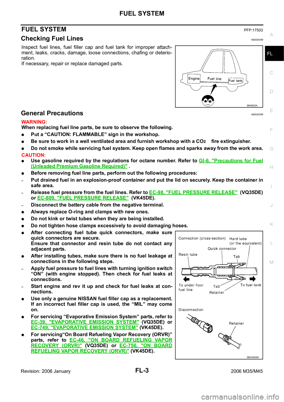
Inspect fuel lines, fuel filler cap and fuel tank for improper attach-
ment, leaks, cracks, damage, loose connections, chafing or deterio-
ration.
If necessary, repair or replace damaged parts.
General PrecautionsNBS005R9
WAR NING :
When replacing fuel line parts, be sure to observe the following.
Put a “CAUTION: FLAMMABLE” sign in the workshop.
Be sure to work in a well ventilated area and furnish workshop with a CO2 fire extinguisher.
Do not smoke while servicing fuel system. Keep open flames and sparks away from the work area.
CAUTION:
Use gasoline required by the regulations for octane number. Refer to GI-6, "Precautions for Fuel
(Unleaded Premium Gasoline Required)" .
Before removing fuel line parts, perform out the following procedures:
–Put drained fuel in an explosion-proof container and put the lid on securely. Keep the container in
safe area.
–Release fuel pressure from the fuel lines. Refer to EC-98, "FUEL PRESSURE RELEASE" (VQ35DE)
or EC-809, "
FUEL PRESSURE RELEASE" (VK45DE).
–Disconnect the battery cable from the negative terminal.
Always replace O-ring and clamps with new ones.
Do not kink or twist tubes when they are being installed.
Do not tighten hose clamps excessively to avoid damaging hoses.
After connecting fuel tube quick connectors, make sure
quick connectors are secure.
Ensure that connector and resin tube do not contact any
adjacent parts.
After installing tubes, make sure there is no fuel leakage at
connections in the following steps.
–Apply fuel pressure to fuel lines with turning ignition switch
“ON” (with engine stopped). Then check for fuel leaks at
connections.
–Start engine and rev it up and check for fuel leaks at con-
nections.
Use only a genuine NISSAN fuel filler cap as a replacement.
If an incorrect fuel filler cap is used, the “MIL” may come
on.
For servicing “Evaporative Emission System” parts, refer to
EC-39, "
EVAPORATIVE EMISSION SYSTEM" (VQ35DE) or
EC-749, "
EVAPORATIVE EMISSION SYSTEM" (VK45DE).
For servicing“On Board Refueling Vapor Recovery (ORVR)”
parts, refer to EC-46, "
ON BOARD REFUELING VAPOR
RECOVERY (ORVR)" (VQ35DE) or EC-756, "ON BOARD
REFUELING VAPOR RECOVERY (ORVR)" (VK45DE).
SMA803A
SBIA0504E
Page 3464 of 5621
GI-1
GENERAL INFORMATION
A GENERAL INFORMATION
CONTENTS
C
D
E
F
G
H
I
J
K
L
MB
GI
SECTION GI
Revision: 2006 January2006 M35/M45
GENERAL INFORMATION
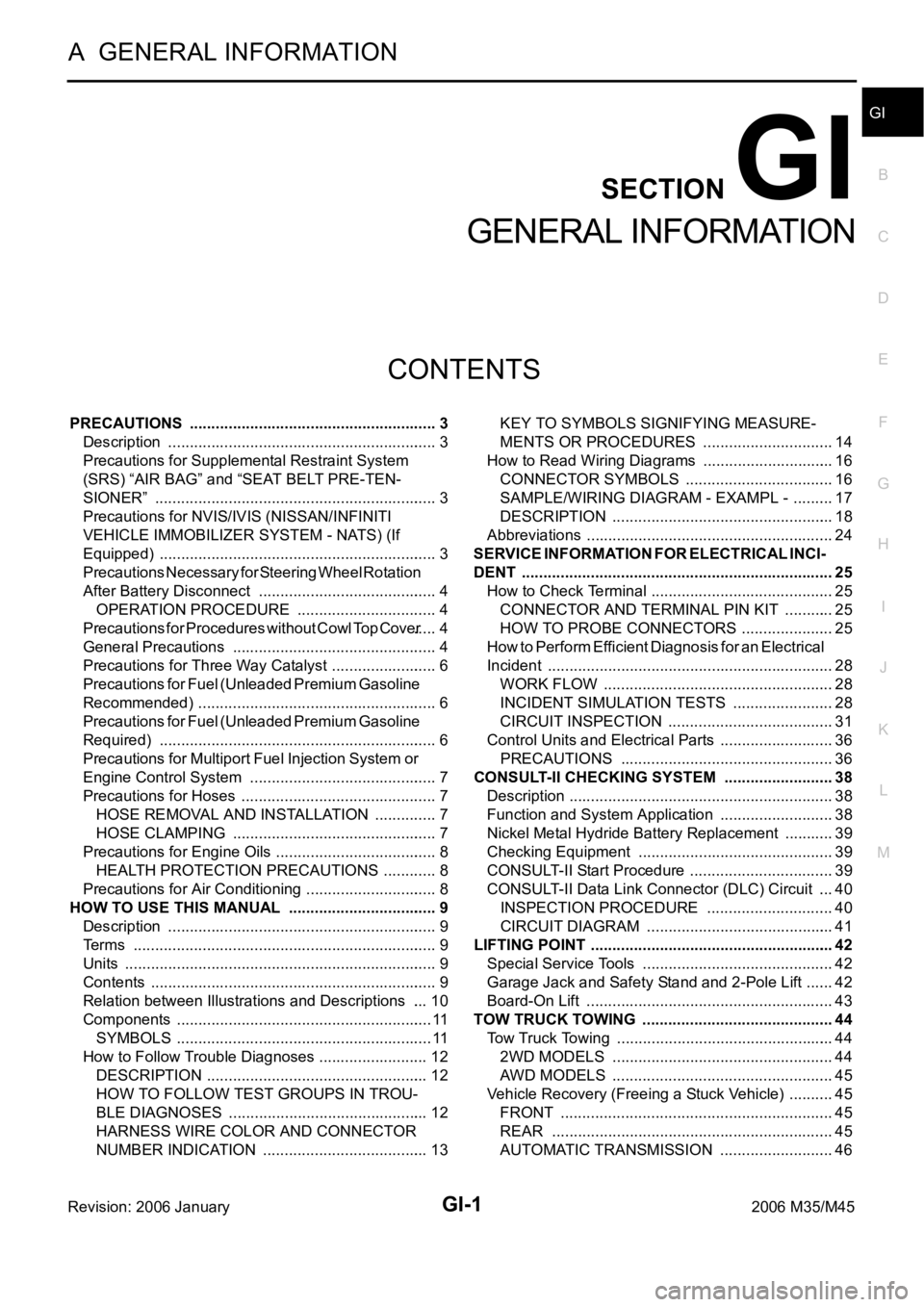
PRECAUTIONS .......................................................... 3
Description ............................................................... 3
Precautions for Supplemental Restraint System
(SRS) “AIR BAG” and “SEAT BELT PRE-TEN-
SIONER” .................................................................. 3
Precautions for NVIS/IVIS (NISSAN/INFINITI
VEHICLE IMMOBILIZER SYSTEM - NATS) (If
Equipped) ................................................................. 3
Precautions Necessary for Steering Wheel Rotation
After Battery Disconnect .......................................... 4
OPERATION PROCEDURE ................................. 4
Precautions for Procedures without Cowl Top Cover ..... 4
General Precautions ................................................ 4
Precautions for Three Way Catalyst ......................... 6
Precautions for Fuel (Unleaded Premium Gasoline
Recommended) ...................................................
..... 6
Precautions for Fuel (Unleaded Premium Gasoline
Required) ................................................................. 6
Precautions for Multiport Fuel Injection System or
Engine Control System ............................................ 7
Precautions for Hoses .............................................. 7
HOSE REMOVAL AND INSTALLATION ............... 7
HOSE CLAMPING ................................................ 7
Precautions for Engine Oils ...................................... 8
HEALTH PROTECTION PRECAUTIONS ............. 8
Precautions for Air Conditioning ............................... 8
HOW TO USE THIS MANUAL ................................... 9
Description ............................................................... 9
Terms ....................................................................... 9
Units ......................................................................... 9
Contents ................................................................... 9
Relation between Illustrations and Descriptions .... 10
Components ............................................................ 11
SYMBOLS ........................................................
.... 11
How to Follow Trouble Diagnoses .......................... 12
DESCRIPTION .................................................... 12
HOW TO FOLLOW TEST GROUPS IN TROU-
BLE DIAGNOSES ............................................... 12
HARNESS WIRE COLOR AND CONNECTOR
NUMBER INDICATION ....................................... 13KEY TO SYMBOLS SIGNIFYING MEASURE-
MENTS OR PROCEDURES ............................... 14
How to Read Wiring Diagrams ............................... 16
CONNECTOR SYMBOLS ................................... 16
SAMPLE/WIRING DIAGRAM - EXAMPL - .......... 17
DESCRIPTION .................................................... 18
Abbreviations .......................................................... 24
SERVICE INFORMATION FOR ELECTRICAL INCI-
DENT ......................................................................... 25
How to Check Terminal ........................................... 25
CONNECTOR AND TERMINAL PIN KIT ............ 25
HOW TO PROBE CONNECTORS ...................... 25
How to Perform Efficient Diagnosis for an Electrical
Incident ................................................................... 28
WORK FLOW ...................................................... 28
INCIDENT SIMULATION TESTS ........................ 28
CIRCUIT INSPECTION ....................................
... 31
Control Units and Electrical Parts ........................... 36
PRECAUTIONS .................................................. 36
CONSULT-II CHECKING SYSTEM .......................... 38
Description .............................................................. 38
Function and System Application ........................... 38
Nickel Metal Hydride Battery Replacement ............ 39
Checking Equipment .............................................. 39
CONSULT-II Start Procedure .................................. 39
CONSULT-II Data Link Connector (DLC) Circuit .... 40
INSPECTION PROCEDURE .............................. 40
CIRCUIT DIAGRAM ............................................ 41
LIFTING POINT ......................................................... 42
Special Service Tools ............................................. 42
Garage Jack and Safety Stand and 2-Pole Lift ....... 42
Board-On Lift .......................................................... 43
TOW TRUCK TOWING ............................................. 44
Tow Truck Towing ................................................... 44
2WD MODELS .................................................... 44
AWD MODELS .................................................... 45
Vehicle Recovery (Freeing a Stuck Vehicle) ........... 45
FRONT ................................................................ 45
REAR .................................................................. 45
AUTOMATIC TRANSMISSION ........................... 46
Page 3502 of 5621
CONSULT-II CHECKING SYSTEM
GI-39
C
D
E
F
G
H
I
J
K
L
MB
GI
Revision: 2006 January2006 M35/M45
Nickel Metal Hydride Battery Replacement NAS0007U
CONSULT-II contains a nickel metal hydride battery. When replacing the battery obey the following:
WAR NING :
Replace the nickel metal hydride battery with Genuine CONSULT-II battery only. Use of another bat-
tery may present a risk of fire or explosion. The battery may present a fire or chemical burn hazard if
mistreated. Do not recharge, disassemble or dispose of in fire.
Keep the battery out of reach of children and discard used battery conforming to the local regulations.
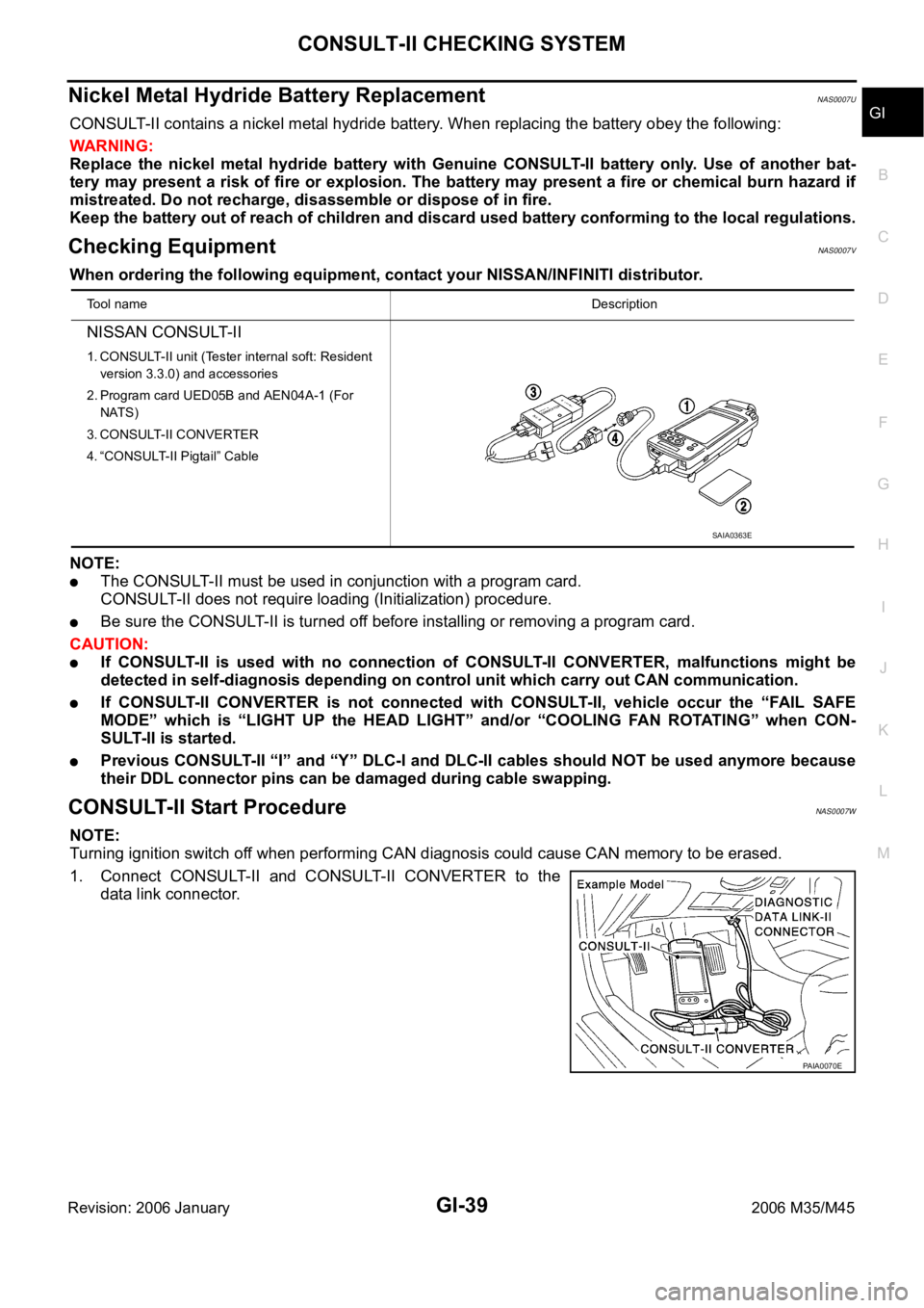
Checking Equipment NAS0007V
When ordering the following equipment, contact your NISSAN/INFINITI distributor.
NOTE:
The CONSULT-II must be used in conjunction with a program card.
CONSULT-II does not require loading (Initialization) procedure.
Be sure the CONSULT-II is turned off before installing or removing a program card.
CAUTION:
If CONSULT-II is used with no connection of CONSULT-II CONVERTER, malfunctions might be
detected in self-diagnosis depending on control unit which carry out CAN communication.
If CONSULT-II CONVERTER is not connected with CONSULT-II, vehicle occur the “FAIL SAFE
MODE” which is “LIGHT UP the HEAD LIGHT” and/or “COOLING FAN ROTAT I N G ” w h e n C O N -
SULT-II is started.
Previous CONSULT-II “I” and “Y” DLC-I and DLC-II cables should NOT be used anymore because
their DDL connector pins can be damaged during cable swapping.
CONSULT-II Start ProcedureNAS0007W
NOTE:
Turning ignition switch off when performing CAN diagnosis could cause CAN memory to be erased.
1. Connect CONSULT-II and CONSULT-II CONVERTER to the
data link connector.
Tool nameDescription
NISSAN CONSULT-II
1. CONSULT-II unit (Tester internal soft: Resident
version 3.3.0) and accessories
2. Program card UED05B and AEN04A-1 (For
NATS)
3. CONSULT-II CONVERTER
4. “CONSULT-II Pigtail” Cable
SAIA0363E
PAIA0070E
Page 3643 of 5621
IDX-2
ALPHABETICAL INDEX
A
A/C air flow ...................................................... ATC-37
A/C component layout ..................................... ATC-25
A/C compressor mounting ........... ATC-155, ATC-158,
ATC-159
, ATC-160, ATC-162, ATC-164, ATC-165,
ATC-167
, ATC-168, ATC-169
A/C compressor precaution ............................. ATC-12
A/C compressor special service tool ................ ATC-16
A/C control operation (auto A/C) ...................... ATC-33
A/C diagnostic work flow (auto A/C) .............. ATC-111
A/C evaporator ............................................... ATC-168
A/C HFC134a (R134a) system precaution ........ ATC-6
A/C HFC134a (R134a) system service procedure .......
ATC-151
A/C HFC134a (R134a) system service tools ... ATC-17
A/C HFC134a system service equipment precaution ...
ATC-13
A/C lubricant (R134a) ...................................... ATC-26
A/C lubrication oil ........................................... ATC-174
A/C operational check ...................................... ATC-64
A/C self-diagnoses (auto A/C) ........ ATC-55, ATC-111
A/C service data specification ........................ ATC-174
A/C system description (auto A/C) ................... ATC-29
A/C trouble diagnoses (auto A/C) .................... ATC-40
A/C, A - Wiring diagram ................................... ATC-46
A/T fluid checking ...................... AT-13, AT-53, MA-29
A/T fluid cooler cleaning .................................... AT-14
A/T fluid replacement ............................. AT-12, MA-31
A/T fluid temperature sensor ........................... AT-135
A/T IND - Wiring diagram .................................... DI-57
A/T self-diagnoses ............................... AT-92, AT-103
A/T shift lock system ........................................ AT-229
A/T shift lock system - Wiring diagram ............ AT-230
A/T trouble diagnoses ........................................ AT-44
Accelerator control system ............................... ACC-3
Accelerator pedal position (APP) sensor ........ EC-626,
EC-633
, EC-647, EC-1358, EC-1365, EC-1379
Accelerator pedal released position learning .... EC-95,
EC-806
AF1B1-Wiring diagram ...... EC-249, EC-258, EC-267,
EC-277
, EC-657, EC-972, EC-981, EC-990, EC-1000,
EC-1389
AF1B2-Wiring diagram ...... EC-251, EC-260, EC-269,
EC-279
, EC-659, EC-974, EC-983, EC-992, EC-1002,
EC-1391
AF1HB1-Wiring diagram .................... EC-183, EC-905
AF1HB2-Wiring diagram .................... EC-185, EC-907
Air bag .............................................................. SRS-3
Air bag precautions ........................................... SRS-3
Air cleaner and air duct(VK45DE) ................... EM-177
Air cleaner and air duct(VQ35DE) .................... EM-17
Air cleaner filter replacement ............................ MA-25
Air cleaner filter replacement(VQ35DE) ........... MA-18
Air cleaner filter(VQ35DE) ................................ EM-18
Air conditioner cut control .................... EC-35, EC-745
Air flow meter - See Mass air flow sensor ...... EC-205,
EC-214
, EC-927, EC-936
Air fuel ratio sensor 1 ......... EC-246, EC-256, EC-265, EC-274
, EC-655, EC-969, EC-979, EC-988, EC-997,
EC-1387
Air fuel ratio sensor 1 heater ............. EC-182, EC-904
Air mix. door motor ......................... ATC-83, ATC-141
Alternator ........................................................... SC-23
Ambient sensor ............................. ATC-113, ATC-126
Angular tightening application ............................. EM-6
Angular tightening application(VK45DE) ........ EM-164
APPS1 - Wiring diagram ................. EC-628, EC-1360
APPS2 - Wiring diagram ................. EC-635, EC-1367
APPS3 - Wiring diagram ................. EC-649, EC-1381
ASC/BS - Wiring diagram ............... EC-587, EC-1313
ASC/SW - Wiring diagram .............. EC-570, EC-1296
ASCBOF - Wiring diagram .............. EC-708, EC-1450
ASCD .................................................. EC-36, EC-746
ASCD (automatic speed control device) ........... ACS-3
ASCIND - Wiring diagram ............... EC-715, EC-1457
AT indicator lamp ................................................ DI-56
Auto air conditioner - Wiring diagram ............. ATC-46
Auto amp ...................................................... ATC-125
Auto anti-dazzling inside mirror .......... GW-71, GW-72
Automatic amplifier ........... ATC-53, ATC-66, ATC-125
Automatic transmission fluid replacement ........ MA-32
AWD - Wiring diagram ....................................... TF-17
Axle ................................................................... MA-37
B
Back-up lamp ................................................... LT-246
Basic inspection .................................. EC-77, EC-788
Battery ................................................................. SC-4
Battery current sensor ....... EC-537, EC-543, EC-549,
EC-555
, EC-1263, EC-1269, EC-1275, EC-1281
Battery/Starting/Charging System Tester .......... SC-28
Battery/Starting/Charging System Tester(Battery) SC-7
Battery/Starting/Charging System Tester(Starting
system) .............................................................. SC-13
BCM (Body control module) .............................. BCS-3
Block heater(VK45DE) .................................... EM-249
Block heater(VQ35DE) ................................... EM-123
Blower motor ................................... ATC-89, ATC-132
Blower unit .................................................... ATC-130
Brake fluid level ................................................ MA-35
Brake hydraulic line ........................................... BR-12
Brake inspection ............................................... MA-36
Brake lines and cables inspection .................... MA-35
Brake pedal .......................................................... BR-6
Brake switch ................................... EC-598, EC-1329
BRK/SW - Wiring diagram .............. EC-600, EC-1331
Bulb specifications ........................................... LT-315
Bumper, front ...................................................... EI-11
Bumper, rear ....................................................... EI-14
C
Camshaft inspection(VK45DE) ....................... EM-216
Camshaft inspection(VQ35DE) ......................... EM-86
Camshaft position sensor (PHASE) EC-383, EC-1106
Camshaft(VK45DE) ........................................ EM-215
Page 4428 of 5621
LT-1
LIGHTING SYSTEM
K ELECTRICAL
CONTENTS
C
D
E
F
G
H
I
J
L
M
SECTION LT
A
B
LT
Revision: 2006 January2006 M35/M45
LIGHTING SYSTEM
PRECAUTIONS .......................................................... 6
Precautions for Supplemental Restraint System
(SRS) “AIR BAG” and “SEAT BELT PRE-TEN-
SIONER” .................................................................. 6
General Precautions for Service Operations ............ 7
HEADLAMP (FOR USA) - CONVENTIONAL TYPE - ..... 8
Component Parts and Harness Connector Location ..... 8
System Description .................................................. 8
OUTLINE ............................................................... 9
HEADLAMP OPERATION .................................. 10
COMBINATION SWITCH READING FUNCTION .... 11
EXTERIOR LAMP BATTERY SAVER CONTROL .... 11
AUTO LIGHT OPERATION .................................. 11
CAN Communication System Description ............... 11
CAN Communication Unit ....................................... 11
Schematic .............................................................. 12
Wiring Diagram — H/LAMP — ............................... 13
Terminals and Reference Values for BCM ............. 18
Terminals and Reference Values for IPDM E/R ..... 20
How to Perform Trouble Diagnoses ....................... 20
Preliminary Check .................................................. 20
CHECK POWER SUPPLY AND GROUND CIR-
CUIT .................................................................... 20
CONSULT-II Functions (BCM) ............................... 22
CONSULT-II BASIC OPERATION ....................... 22
DATA MONITOR ................................................. 23
ACTIVE TEST ..................................................... 24
CONSULT-II Functions (IPDM E/R) ....................... 25
CONSULT-II BASIC OPERATION ....................... 25
DATA MONITOR ................................................. 26
ACTIVE TEST ..................................................... 26
Headlamp High Beam Does Not Illuminate (Both
Sides) ..................................................................... 27
Headlamp High Beam Does Not Illuminate (One
Side) ....................................................................... 30
High Beam Indicator Lamp Does Not Illuminate .... 31
Headlamp Low Beam Does Not Illuminate (Both
Sides) ..................................................................... 32
Headlamp Low Beam Does Not Illuminate (One
Side) ....................................................................... 35Headlamps Do Not Turn OFF ................................. 37
Aiming Adjustment .................................................. 38
PREPARATION BEFORE ADJUSTING .............. 38
LOW BEAM AND HIGH BEAM ........................... 38
ADJUSTMENT USING AN ADJUSTMENT
SCREEN (LIGHT/DARK BORDERLINE) ............ 39
Bulb Replacement .................................................. 39
HEADLAMP (INNER) HIGH BEAM ..................... 39
HEADLAMP (OUTER) LOW BEAM .................... 40
PARKING LAMP (CLEARANCE) LAMP .............. 40
FRONT TURN SIGNAL LAMP ............................ 40
FRONT SIDE MARKER LAMP ........................... 40
Removal and Installation ........................................ 41
REMOVAL ........................................................
... 41
INSTALLATION ................................................... 41
Disassembly and Assembly .................................... 42
DISASSEMBLY ................................................... 42
ASSEMBLY ......................................................... 42
HEADLAMP (FOR USA) - XENON TYPE - .............. 43
Component Parts and Harness Connector Location ... 43
System Description ................................................. 43
OUTLINE ............................................................. 44
HEADLAMP OPERATION ................................... 45
COMBINATION SWITCH READING FUNCTION ... 46
EXTERIOR LAMP BATTERY SAVER CONTROL ... 46
AUTO LIGHT OPERATION ................................. 46
XENON HEADLAMP ........................................... 46
CAN Communication System Description .............. 46
CAN Communication Unit ....................................... 46
Schematic ............................................................... 47
Wiring Diagram — H/LAMP — ............................... 48
Terminals and Reference Values for BCM .............. 53
Terminals and Reference Values for IPDM E/R ...... 55
How to Perform Trouble Diagnoses ....................... 55
Preliminary Check .................................................. 55
CHECK POWER SUPPLY AND GROUND CIR-
CUIT .................................................................... 55
CONSULT-II Functions (BCM) ................................ 57
CONSULT-II BASIC OPERATION ....................... 57
DATA MONITOR ................................................. 58