Page 4961 of 5621

PS-8
POWER STEERING FLUID
Revision: 2006 January2006 M35/M45
POWER STEERING FLUIDPFP:KLF20
Checking Fluid LevelNGS000D5
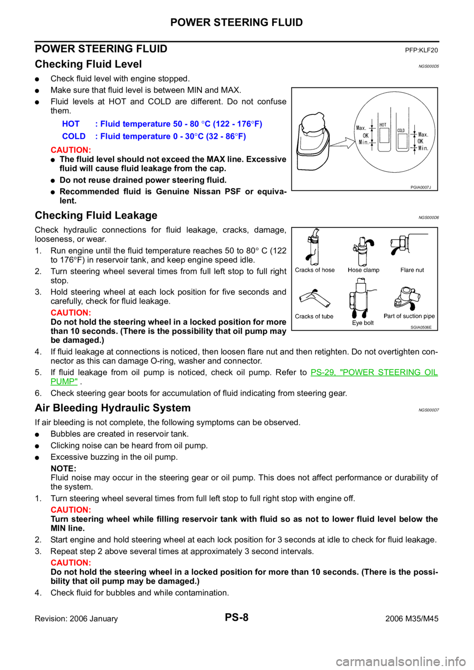
Check fluid level with engine stopped.
Make sure that fluid level is between MIN and MAX.
Fluid levels at HOT and COLD are different. Do not confuse
them.
CAUTION:
The fluid level should not exceed the MAX line. Excessive
fluid will cause fluid leakage from the cap.
Do not reuse drained power steering fluid.
Recommended fluid is Genuine Nissan PSF or equiva-
lent.
Checking Fluid LeakageNGS000D6
Check hydraulic connections for fluid leakage, cracks, damage,
looseness, or wear.
1. Run engine until the fluid temperature reaches 50 to 80
C (122
to 176
F) in reservoir tank, and keep engine speed idle.
2. Turn steering wheel several times from full left stop to full right
stop.
3. Hold steering wheel at each lock position for five seconds and
carefully, check for fluid leakage.
CAUTION:
Do not hold the steering wheel in a locked position for more
than 10 seconds. (There is the possibility that oil pump may
be damaged.)
4. If fluid leakage at connections is noticed, then loosen flare nut and then retighten. Do not overtighten con-
nector as this can damage O-ring, washer and connector.
5. If fluid leakage from oil pump is noticed, check oil pump. Refer to PS-29, "
POWER STEERING OIL
PUMP" .
6. Check steering gear boots for accumulation of fluid indicating from steering gear.
Air Bleeding Hydraulic SystemNGS000D7
If air bleeding is not complete, the following symptoms can be observed.
Bubbles are created in reservoir tank.
Clicking noise can be heard from oil pump.
Excessive buzzing in the oil pump.
NOTE:
Fluid noise may occur in the steering gear or oil pump. This does not affect performance or durability of
the system.
1. Turn steering wheel several times from full left stop to full right stop with engine off.
CAUTION:
Turn steering wheel while filling reservoir tank with fluid so as not to lower fluid level below the
MIN line.
2. Start engine and hold steering wheel at each lock position for 3 seconds at idle to check for fluid leakage.
3. Repeat step 2 above several times at approximately 3 second intervals.
CAUTION:
Do not hold the steering wheel in a locked position for more than 10 seconds. (There is the possi-
bility that oil pump may be damaged.)
4. Check fluid for bubbles and while contamination.HOT : Fluid temperature 50 - 80
C (122 - 176F)
COLD : Fluid temperature 0 - 30
C (32 - 86F)
PGIA0007J
SGIA0506E
Page 4972 of 5621

POWER STEERING GEAR
PS-19
C
D
E
F
H
I
J
K
L
MA
B
PS
Revision: 2006 January2006 M35/M45
8. Remove steering hydraulic piping bracket from front suspension member. Refer to PS-38, "HYDRAULIC
LINE" .
9. Remove EPS solenoid valve harness connector. Refer to PS-20, "
COMPONENTS" .
10. Remove rack stay (2WD) or front cross bar (AWD). Refer to FSU-8, "
Components" , FSU-25, "Compo-
nents" .
11. Remove mounting bolts and nuts of steering gear assembly, and then remove steering gear assembly
from vehicle.
INSTALLATION
Installation is the reverse order of removal. For tightening torque, refer to PS-18, "COMPONENTS" .
When installing lower joint to steering gear assembly, follow the procedure listed below.
–Set rack of steering gear in the neutral position.
NOTE:
To get the neutral position of rack, turn gear-sub assembly and measure the distance of inner socket, and
then measure the intermediate position of the distance.
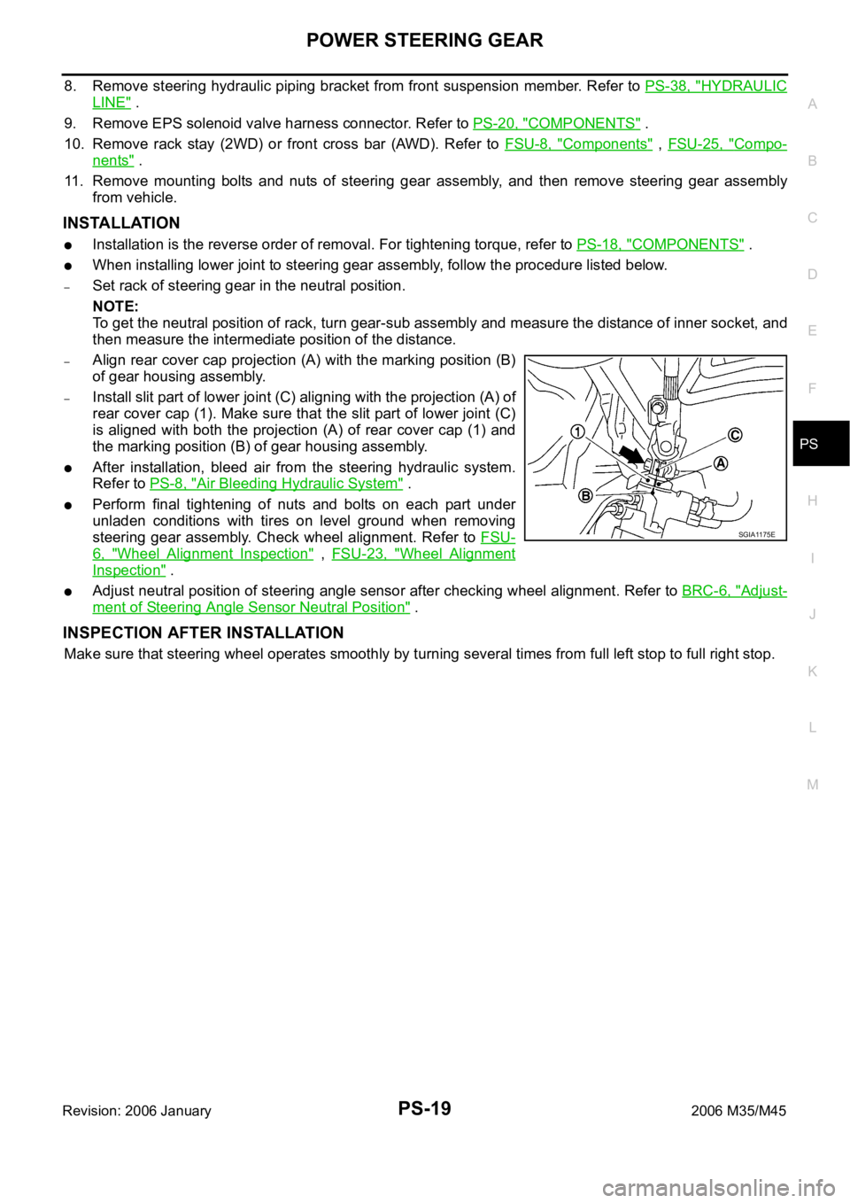
–Align rear cover cap projection (A) with the marking position (B)
of gear housing assembly.
–Install slit part of lower joint (C) aligning with the projection (A) of
rear cover cap (1). Make sure that the slit part of lower joint (C)
is aligned with both the projection (A) of rear cover cap (1) and
the marking position (B) of gear housing assembly.
After installation, bleed air from the steering hydraulic system.
Refer to PS-8, "
Air Bleeding Hydraulic System" .
Perform final tightening of nuts and bolts on each part under
unladen conditions with tires on level ground when removing
steering gear assembly. Check wheel alignment. Refer to FSU-
6, "Wheel Alignment Inspection" , FSU-23, "Wheel Alignment
Inspection" .
Adjust neutral position of steering angle sensor after checking wheel alignment. Refer to BRC-6, "Adjust-
ment of Steering Angle Sensor Neutral Position" .
INSPECTION AFTER INSTALLATION
Make sure that steering wheel operates smoothly by turning several times from full left stop to full right stop.
SGIA1175E
Page 4982 of 5621

POWER STEERING OIL PUMP
PS-29
C
D
E
F
H
I
J
K
L
MA
B
PS
Revision: 2006 January2006 M35/M45
POWER STEERING OIL PUMPPFP:49110
On-Vehicle Inspection and ServiceNGS000DE
CHECKING RELIEF OIL PRESSURE
CAUTION:
Make sure that belt tension is normal before starting the following procedure.
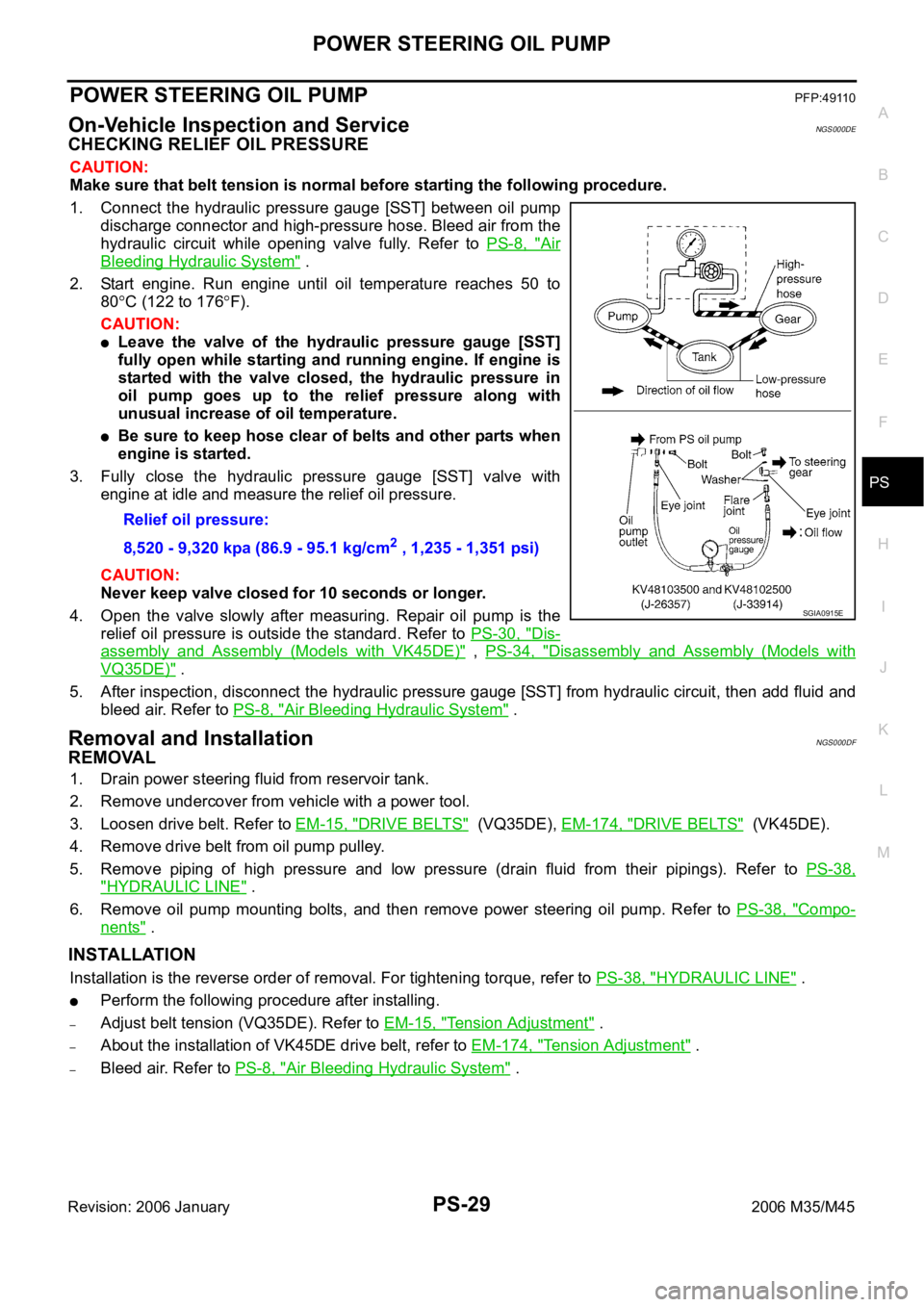
1. Connect the hydraulic pressure gauge [SST] between oil pump
discharge connector and high-pressure hose. Bleed air from the
hydraulic circuit while opening valve fully. Refer to PS-8, "
Air
Bleeding Hydraulic System" .
2. Start engine. Run engine until oil temperature reaches 50 to
80
C (122 to 176F).
CAUTION:
Leave the valve of the hydraulic pressure gauge [SST]
fully open while starting and running engine. If engine is
started with the valve closed, the hydraulic pressure in
oil pump goes up to the relief pressure along with
unusual increase of oil temperature.
Be sure to keep hose clear of belts and other parts when
engine is started.
3. Fully close the hydraulic pressure gauge [SST] valve with
engine at idle and measure the relief oil pressure.
CAUTION:
Never keep valve closed for 10 seconds or longer.
4. Open the valve slowly after measuring. Repair oil pump is the
relief oil pressure is outside the standard. Refer to PS-30, "
Dis-
assembly and Assembly (Models with VK45DE)" , PS-34, "Disassembly and Assembly (Models with
VQ35DE)" .
5. After inspection, disconnect the hydraulic pressure gauge [SST] from hydraulic circuit, then add fluid and
bleed air. Refer to PS-8, "
Air Bleeding Hydraulic System" .
Removal and InstallationNGS000DF
REMOVAL
1. Drain power steering fluid from reservoir tank.
2. Remove undercover from vehicle with a power tool.
3. Loosen drive belt. Refer to EM-15, "
DRIVE BELTS" (VQ35DE), EM-174, "DRIVE BELTS" (VK45DE).
4. Remove drive belt from oil pump pulley.
5. Remove piping of high pressure and low pressure (drain fluid from their pipings). Refer to PS-38,
"HYDRAULIC LINE" .
6. Remove oil pump mounting bolts, and then remove power steering oil pump. Refer to PS-38, "
Compo-
nents" .
INSTALLATION
Installation is the reverse order of removal. For tightening torque, refer to PS-38, "HYDRAULIC LINE" .
Perform the following procedure after installing.
–Adjust belt tension (VQ35DE). Refer to EM-15, "Tension Adjustment" .
–About the installation of VK45DE drive belt, refer to EM-174, "Tension Adjustment" .
–Bleed air. Refer to PS-8, "Air Bleeding Hydraulic System" . Relief oil pressure:
8,520 - 9,320 kpa (86.9 - 95.1 kg/cm
2 , 1,235 - 1,351 psi)
SGIA0915E