Page 4123 of 5621
![INFINITI M35 2006 Factory Service Manual LAN-454
[CAN]
CAN SYSTEM (TYPE 9)
Revision: 2006 January2006 M35/M45
Intelligent Key Unit Circuit InspectionNKS0043N
1. CHECK CONNECTOR
1. Turn ignition switch OFF.
2. Disconnect the battery cable fro](/manual-img/42/57023/w960_57023-4122.png "INFINITI M35 2006 Factory Service Manual LAN-454
[CAN]
CAN SYSTEM (TYPE 9)
Revision: 2006 January2006 M35/M45
Intelligent Key Unit Circuit InspectionNKS0043N
1. CHECK CONNECTOR
1. Turn ignition switch OFF.
2. Disconnect the battery cable fro")
LAN-454
[CAN]
CAN SYSTEM (TYPE 9)
Revision: 2006 January2006 M35/M45
Intelligent Key Unit Circuit InspectionNKS0043N
1. CHECK CONNECTOR
1. Turn ignition switch OFF.
2. Disconnect the battery cable from the negative terminal.
3. Check terminals and connector of Intelligent Key unit for damage, bend and loose connection (unit side
and harness side).
OK or NG
OK >> GO TO 2.
NG >> Repair terminal or connector.
2. CHECK HARNESS FOR OPEN CIRCUIT
1. Disconnect Intelligent Key unit connector.
2. Check resistance between Intelligent Key unit harness connec-
tor terminals.
OK or NG
OK >> Replace Intelligent Key unit.
NG >> Repair harness between Intelligent Key unit and data
link connector.
Unified Meter and A/C Amp. Circuit InspectionNKS0043O
1. CHECK CONNECTOR
1. Turn ignition switch OFF.
2. Disconnect the battery cable from the negative terminal.
3. Check terminals and connector of unified meter and A/C amp. for damage, bend and loose connection
(meter side and harness side).
OK or NG
OK >> GO TO 2.
NG >> Repair terminal or connector.
2. CHECK HARNESS FOR OPEN CIRCUIT
1. Disconnect unified meter and A/C amp. connector.
2. Check resistance between unified meter and A/C amp. harness
connector terminals.
OK or NG
OK >> Replace unified meter and A/C amp.
NG >> Repair harness between unified meter and A/C amp.
and data link connector.
Intelligent Key
unit connectorTerminalResistance
(Approx.)
M32 38 37 54 – 66
PKIC0286E
Unified meter
and A/C amp.
connectorTerminalResistance
(Approx.)
M65 56 72 54 – 66
PKIC0287E
Page 4124 of 5621
![INFINITI M35 2006 Factory Service Manual CAN SYSTEM (TYPE 9)
LAN-455
[CAN]
C
D
E
F
G
H
I
J
L
MA
B
LAN
Revision: 2006 January2006 M35/M45
NAVI Control Unit Circuit InspectionNKS0043P
1. CHECK CONNECTOR
1. Turn ignition switch OFF.
2. Disconne](/manual-img/42/57023/w960_57023-4123.png "INFINITI M35 2006 Factory Service Manual CAN SYSTEM (TYPE 9)
LAN-455
[CAN]
C
D
E
F
G
H
I
J
L
MA
B
LAN
Revision: 2006 January2006 M35/M45
NAVI Control Unit Circuit InspectionNKS0043P
1. CHECK CONNECTOR
1. Turn ignition switch OFF.
2. Disconne")
CAN SYSTEM (TYPE 9)
LAN-455
[CAN]
C
D
E
F
G
H
I
J
L
MA
B
LAN
Revision: 2006 January2006 M35/M45
NAVI Control Unit Circuit InspectionNKS0043P
1. CHECK CONNECTOR
1. Turn ignition switch OFF.
2. Disconnect the battery cable from the negative terminal.
3. Check following terminals and connectors for damage, bend and loose connection (control unit side and
harness side).
–NAVI control unit connector
–Harness connector M216
–Harness connector M53
OK or NG
OK >> GO TO 2.
NG >> Repair terminal or connector.
2. CHECK HARNESS FOR OPEN CIRCUIT
1. Disconnect NAVI control unit connector.
2. Check resistance between NAVI control unit harness connector
terminals.
OK or NG
OK >> Replace NAVI control unit.
NG >> Repair harness between NAVI control unit and data link
connector.
Data Link Connector Circuit InspectionNKS0043Q
1. CHECK CONNECTOR
1. Turn ignition switch OFF.
2. Disconnect the battery cable from the negative terminal.
3. Check data link connector and terminals for damage, bend and loose connection (connector side and har-
ness side).
OK or NG
OK >> GO TO 2.
NG >> Repair terminal or connector.
2. CHECK HARNESS FOR OPEN CIRCUIT
Check resistance between data link connector terminals.
OK or NG
OK >> Diagnose again. Refer to LAN-9, "TROUBLE DIAG-
NOSES WORK FLOW" .
NG >> Repair harness between data link connector and har-
ness connector M13.
NAVI control unit
connectorTerminalResistance
(Approx.)
M210 71 72 54 – 66
PKIC0288E
Data link
connectorTerminalResistance
(Approx.)
M60 6 14 54 – 66
PKIA9865E
Page 4125 of 5621
![INFINITI M35 2006 Factory Service Manual LAN-456
[CAN]
CAN SYSTEM (TYPE 9)
Revision: 2006 January2006 M35/M45
RAS Control Unit Circuit InspectionNKS0043R
1. CHECK CONNECTOR
1. Turn ignition switch OFF.
2. Disconnect the battery cable from th](/manual-img/42/57023/w960_57023-4124.png "INFINITI M35 2006 Factory Service Manual LAN-456
[CAN]
CAN SYSTEM (TYPE 9)
Revision: 2006 January2006 M35/M45
RAS Control Unit Circuit InspectionNKS0043R
1. CHECK CONNECTOR
1. Turn ignition switch OFF.
2. Disconnect the battery cable from th")
LAN-456
[CAN]
CAN SYSTEM (TYPE 9)
Revision: 2006 January2006 M35/M45
RAS Control Unit Circuit InspectionNKS0043R
1. CHECK CONNECTOR
1. Turn ignition switch OFF.
2. Disconnect the battery cable from the negative terminal.
3. Check terminals and connector of RAS control unit for damage, bend and loose connection (control unit
side and harness side).
OK or NG
OK >> GO TO 2.
NG >> Repair terminal or connector.
2. CHECK HARNESS FOR OPEN CIRCUIT
1. Disconnect RAS control unit connector.
2. Check resistance between RAS control unit harness connector
terminals.
OK or NG
OK >> Replace RAS control unit.
NG >> Replace harness.
Pre-Crash Seat Belt Control Unit Circuit InspectionNKS0043S
1. CHECK CONNECTOR
1. Turn ignition switch OFF.
2. Disconnect the battery cable from the negative terminal.
3. Check terminals and connector of pre-crash seat belt control unit for damage, bend and loose connection
(control unit side and harness side).
OK or NG
OK >> GO TO 2.
NG >> Repair terminal or connector.
2. CHECK HARNESS FOR OPEN CIRCUIT
1. Disconnect pre-crash seat belt control unit connector.
2. Check resistance between pre-crash seat belt control unit har-
ness connector terminals.
OK or NG
OK >> Replace pre-crash seat belt control unit.
NG >> Replace harness.
RAS control unit
connectorTerminalResistance
(Approx.)
B127 1 8 54 – 66
PKIC0303E
Pre-crash seat
belt control unit
connectorTerminalResistance
(Approx.)
B142 24 22 54 – 66
PKIA9863E
Page 4126 of 5621
![INFINITI M35 2006 Factory Service Manual CAN SYSTEM (TYPE 9)
LAN-457
[CAN]
C
D
E
F
G
H
I
J
L
MA
B
LAN
Revision: 2006 January2006 M35/M45
Driver Seat Control Unit Circuit InspectionNKS0043T
1. CHECK CONNECTOR
1. Turn ignition switch OFF.
2. D](/manual-img/42/57023/w960_57023-4125.png "INFINITI M35 2006 Factory Service Manual CAN SYSTEM (TYPE 9)
LAN-457
[CAN]
C
D
E
F
G
H
I
J
L
MA
B
LAN
Revision: 2006 January2006 M35/M45
Driver Seat Control Unit Circuit InspectionNKS0043T
1. CHECK CONNECTOR
1. Turn ignition switch OFF.
2. D")
CAN SYSTEM (TYPE 9)
LAN-457
[CAN]
C
D
E
F
G
H
I
J
L
MA
B
LAN
Revision: 2006 January2006 M35/M45
Driver Seat Control Unit Circuit InspectionNKS0043T
1. CHECK CONNECTOR
1. Turn ignition switch OFF.
2. Disconnect the battery cable from the negative terminal.
3. Check following terminals and connectors for damage, bend and loose connection (control unit side and
harness side).
–Driver seat control unit connector
–Harness connector B202
–Harness connector B15
OK or NG
OK >> GO TO 2.
NG >> Repair terminal or connector.
2. CHECK HARNESS FOR OPEN CIRCUIT
1. Disconnect driver seat control unit connector.
2. Check resistance between driver seat control unit harness con-
nector terminals.
OK or NG
OK >> Replace driver seat control unit.
NG >> Replace harness.
ABS Actuator and Electric Unit (Control Unit) Circuit InspectionNKS0043U
1. CHECK CONNECTOR
1. Turn ignition switch OFF.
2. Disconnect the battery cable from the negative terminal.
3. Check terminals and connector of ABS actuator and electric unit (control unit) for damage, bend and loose
connection (control unit side and harness side).
OK or NG
OK >> GO TO 2.
NG >> Repair terminal or connector.
2. CHECK HARNESS FOR OPEN CIRCUIT
1. Disconnect ABS actuator and electric unit (control unit) connector.
2. Check resistance between ABS actuator and electric unit (con-
trol unit) harness connector terminals.
OK or NG
OK >> Replace ABS actuator and electric unit (control unit).
NG >> Repair harness between ABS actuator and electric unit
(control unit) and IPDM E/R.
Driver seat control
unit connectorTerminalResistance
(Approx.)
B204 3 19 54 – 66
PKIA6842E
ABS actuator and
electric unit
(control unit)
connectorTerminalResistance
(Approx.)
E30 35 14 54 – 66
PKIC0289E
Page 4127 of 5621
LAN-458
[CAN]
CAN SYSTEM (TYPE 9)
Revision: 2006 January2006 M35/M45
IPDM E/R Circuit InspectionNKS0043V
1. CHECK CONNECTOR
1. Turn ignition switch OFF.
2. Disconnect the battery cable from the negative terminal.
3. Check terminals and connector of IPDM E/R for damage, bend and loose connection (control module side
and harness side).
OK or NG
OK >> GO TO 2.
NG >> Repair terminal or connector.
2. CHECK HARNESS FOR OPEN CIRCUIT
1. Disconnect IPDM E/R connector.
2. Check resistance between IPDM E/R harness connector termi-
nals.
OK or NG
OK >> Replace IPDM E/R.
NG >> Repair harness between IPDM E/R and harness con-
nector E105.
IPDM E/R
connectorTerminalResistance
(Approx.)
E9 49 50 108 – 132
PKIC0290E
Page 4128 of 5621
![INFINITI M35 2006 Factory Service Manual CAN SYSTEM (TYPE 9)
LAN-459
[CAN]
C
D
E
F
G
H
I
J
L
MA
B
LAN
Revision: 2006 January2006 M35/M45
CAN Communication Circuit InspectionNKS0043W
1. CHECK CONNECTOR
1. Turn ignition switch OFF.
2. Disconne](/manual-img/42/57023/w960_57023-4127.png "INFINITI M35 2006 Factory Service Manual CAN SYSTEM (TYPE 9)
LAN-459
[CAN]
C
D
E
F
G
H
I
J
L
MA
B
LAN
Revision: 2006 January2006 M35/M45
CAN Communication Circuit InspectionNKS0043W
1. CHECK CONNECTOR
1. Turn ignition switch OFF.
2. Disconne")
CAN SYSTEM (TYPE 9)
LAN-459
[CAN]
C
D
E
F
G
H
I
J
L
MA
B
LAN
Revision: 2006 January2006 M35/M45
CAN Communication Circuit InspectionNKS0043W
1. CHECK CONNECTOR
1. Turn ignition switch OFF.
2. Disconnect the battery cable from the negative terminal.
3. Check following terminals and connectors for damage, bend and loose connection (control module side,
control unit side, unit side, sensor side, meter side and harness side).
–ECM
–A/T assembly
–AFS control unit
–BCM
–Low tire pressure warning control unit
–Steering angle sensor
–Intelligent Key unit
–Unified meter and A/C amp.
–NAVI control unit
–RAS control unit
–Pre-crash seat belt control unit
–Driver seat control unit
–ABS actuator and electric unit (control unit)
–IPDM E/R
–Between ECM and A/T assembly
–Between ECM and AFS control unit
–Between ECM and NAVI control unit
–Between ECM and driver seat control unit
–Between ECM and IPDM E/R
OK or NG
OK >> GO TO 2.
NG >> Repair terminal or connector.
2. CHECK HARNESS FOR SHORT CIRCUIT
1. Disconnect following connectors.
–ECM connector
–Harness connector M72
–BCM connector
–Harness connector M61
2. Check continuity between ECM harness connector terminals.
OK or NG
OK >> GO TO 3.
NG >> Check the following harnesses. If any harness is dam-
aged, repair the harness.
Harness between ECM and harness connector M72
Harness between ECM and BCM
Harness between ECM and harness connector M61
ECM connector Terminal Continuity
M71 94 86 No
PKIA9860E
Page 4135 of 5621
![INFINITI M35 2006 Factory Service Manual LAN-466
[CAN]
CAN SYSTEM (TYPE 9)
Revision: 2006 January2006 M35/M45
19. CHECK SYMPTOM
1. Fill in described symptoms on the column “Symptom” in the check sheet.
2. Connect all connectors, and then](/manual-img/42/57023/w960_57023-4134.png "INFINITI M35 2006 Factory Service Manual LAN-466
[CAN]
CAN SYSTEM (TYPE 9)
Revision: 2006 January2006 M35/M45
19. CHECK SYMPTOM
1. Fill in described symptoms on the column “Symptom” in the check sheet.
2. Connect all connectors, and then")
LAN-466
[CAN]
CAN SYSTEM (TYPE 9)
Revision: 2006 January2006 M35/M45
19. CHECK SYMPTOM
1. Fill in described symptoms on the column “Symptom” in the check sheet.
2. Connect all connectors, and then make sure that the symptom is reproduced.
OK or NG
OK >> GO TO 20.
NG >> Refer to LAN-18, "
Example of Filling in Check Sheet When Initial Conditions Are Not Reproduced"
.
20. CHECK UNIT REPRODUCIBILITY
Performs the following procedure for each unit, and then perform reproducibility test.
1. Turn ignition switch OFF.
2. Disconnect the battery cable from the negative terminal.
3. Disconnect the unit connector.
4. Connect the battery cable to the negative terminal.
5. Make sure that the symptom filled in the “Symptom” of the check sheet is reproduced. (Do not confuse it
with the symptom related to removed unit.)
6. Make sure that the same symptom is reproduced.
–A/T assembly
–AFS control unit
–BCM
–Low tire pressure warning control unit
–Steering angle sensor
–Intelligent Key unit
–Unified meter and A/C amp.
–NAVI control unit
–RAS control unit
–Pre-crash seat belt control unit
–Driver seat control unit
–ABS actuator and electric unit (control unit)
–ECM
–IPDM E/R
Check results
Reproduce>>Install removed unit, and then check the other unit.
Not reproduced>>Replace removed unit.
IPDM E/R Ignition Relay Circuit InspectionNKS0043X
Check the following. If no malfunction is found, replace the IPDM E/R.
IPDM E/R power supply circuit. Refer to PG-30, "Check IPDM E/R Power Supply and Ground Circuit" .
Ignition power supply circuit. Refer to PG-12, "IGNITION POWER SUPPLY — IGNITION SW. IN “ON”
AND/OR “START”" .
Page 4168 of 5621
CAN SYSTEM (TYPE 10)
LAN-499
[CAN]
C
D
E
F
G
H
I
J
L
MA
B
LAN
Revision: 2006 January2006 M35/M45
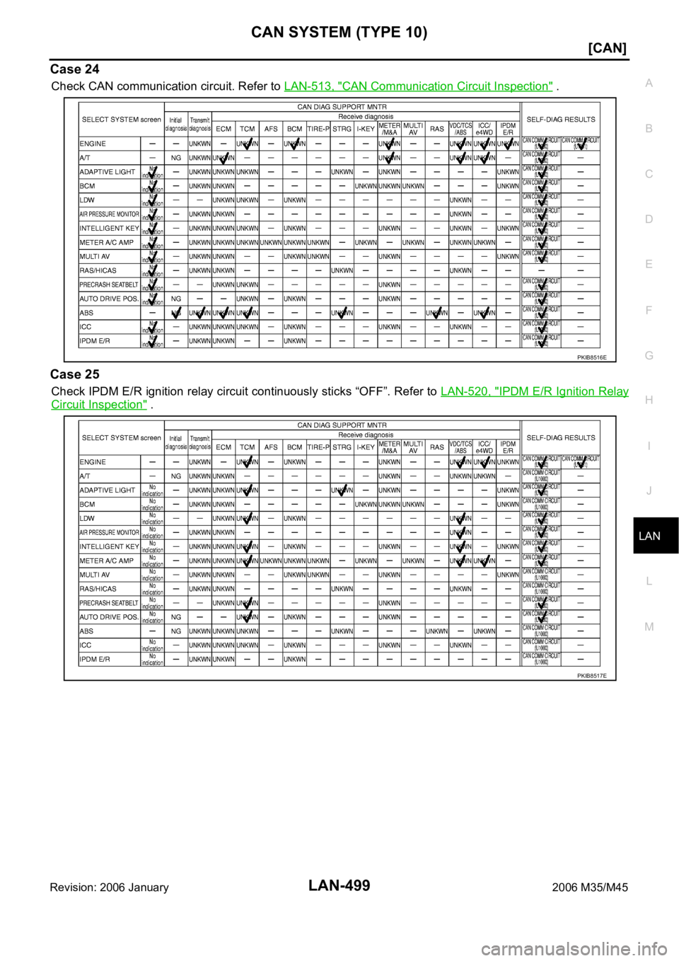
Case 24
Check CAN communication circuit. Refer to LAN-513, "CAN Communication Circuit Inspection" .
Case 25
Check IPDM E/R ignition relay circuit continuously sticks “OFF”. Refer to LAN-520, "IPDM E/R Ignition Relay
Circuit Inspection" .
PKIB8516E
PKIB8517E
![INFINITI M35 2006 Factory Service Manual LAN-458
[CAN]
CAN SYSTEM (TYPE 9)
Revision: 2006 January2006 M35/M45
IPDM E/R Circuit InspectionNKS0043V
1. CHECK CONNECTOR
1. Turn ignition switch OFF.
2. Disconnect the battery cable from the negati](/manual-img/42/57023/w960_57023-4126.png "INFINITI M35 2006 Factory Service Manual LAN-458
[CAN]
CAN SYSTEM (TYPE 9)
Revision: 2006 January2006 M35/M45
IPDM E/R Circuit InspectionNKS0043V
1. CHECK CONNECTOR
1. Turn ignition switch OFF.
2. Disconnect the battery cable from the negati")