2006 INFINITI M35 stall
[x] Cancel search: stallPage 4825 of 5621

PB-6
PARKING BRAKE SHOE
Revision: 2006 January2006 M35/M45
Removal and InstallationNFS000PV
REMOVAL
WAR NING :
Clean brakes with a vacuum dust collector to minimize the hazard of air borne particles or other mate-
rials.
CAUTION:
Clean dust on disc rotor and back plate using a vacuum dust collector. Do not blow with com-
pressed air.
Put matching marks on both disc rotor and wheel hub when removing disc rotor.
1. Remove rear tires from vehicle with power tool.
2. Remove disc rotor with parking brake pedal completely in the released position. Refer to BR-31,
"Removal and Installation of Brake Caliper Assembly" .
3. If disc rotor cannot be removed, remove as follows:
a. Secure the disc rotor in place with wheel nuts and remove adjuster hole plug.
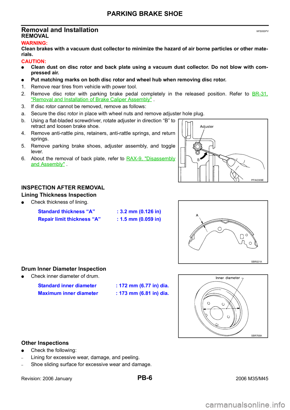
b. Using a flat-bladed screwdriver, rotate adjuster in direction “B” to
retract and loosen brake shoe.
4. Remove anti-rattle pins, retainers, anti-rattle springs, and return
springs.
5. Remove parking brake shoes, adjuster assembly, and toggle
lever.
6. About the removal of back plate, refer to RAX-9, "
Disassembly
and Assembly" .
INSPECTION AFTER REMOVAL
Lining Thickness Inspection
Check thickness of lining.
Drum Inner Diameter Inspection
Check inner diameter of drum.
Other Inspections
Check the following:
–Lining for excessive wear, damage, and peeling.
–Shoe sliding surface for excessive wear and damage.
PFIA0309E
Standard thickness “A” : 3.2 mm (0.126 in)
Repair limit thickness “A” : 1.5 mm (0.059 in)
SBR021A
Standard inner diameter : 172 mm (6.77 in) dia.
Maximum inner diameter : 173 mm (6.81 in) dia.
SBR768A
Page 4826 of 5621

PARKING BRAKE SHOE
PB-7
C
D
E
G
H
I
J
K
L
MA
B
PB
Revision: 2006 January2006 M35/M45
–Anti-rattle pin for excessive wear and corrosion.
–Return spring for sagging.
Make sure that adjuster moves smoothly.
Visually check the inside of drum for excessive wear, cracks, and damage. Check the inside of drum using
a pair of vernier calipers.
Replace with new part if the above part is malfunction.
INSTALLATION
Note the following, and install in the reverse order of removal.
Refer to PB-5, "Components" and apply PBC (Poly Butyl Cupry-
sil) grease or equivalent to the specified points during assembly.
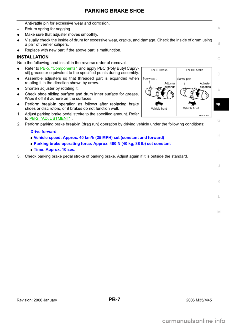
Assemble adjusters so that threaded part is expanded when
rotating it in the direction shown by arrow.
Shorten adjuster by rotating it.
Check shoe sliding surface and drum inner surface for grease.
Wipe it off if it adhere on the surfaces.
Perform break-in operation as follows after replacing brake
shoes or disc rotors, or if brakes do not function well.
1. Adjust parking brake pedal stroke to the specified amount. Refer
to PB-2, "
ADJUSTMENT" .
2. Perform parking brake break-in (drag run) operation by driving vehicle under the following conditions:
3. Check parking brake pedal stroke of parking brake. Adjust again if it is outside the standard. Drive forward
Vehicle speed: Approx. 40 km/h (25 MPH) set (constant and forward)
Parking brake operating force: Approx. 400 N (40 kg, 88 lb) set constant
Time: Approx. 10 sec.
SFIA2426E
Page 4828 of 5621

PG-1
POWER SUPPLY, GROUND & CIRCUIT ELEMENTS
K ELECTRICAL
CONTENTS
C
D
E
F
G
H
I
J
L
M
SECTION PG
A
B
PG
Revision: 2006 January2006 M35/M45
POWER SUPPLY, GROUND & CIRCUIT ELEMENTS
POWER SUPPLY ROUTING CIRCUIT ...................... 3
Schematic ................................................................ 3
Wiring Diagram — POWER — ................................. 5
BATTERY POWER SUPPLY — IGNITION SW.
IN ANY POSITION ................................................ 5
ACCESSORY POWER SUPPLY — IGNITION
SW. IN “ACC” OR “ON” ........................................ 11
IGNITION POWER SUPPLY — IGNITION SW.
IN “ON” AND/OR “START” .................................. 12
Fuse ....................................................................... 17
Fusible Link ............................................................ 17
Circuit Breaker ....................................................... 17
IPDM E/R (INTELLIGENT POWER DISTRIBUTION
MODULE ENGINE ROOM) ...................................... 18
System Description ................................................ 18
SYSTEMS CONTROLLED BY IPDM E/R ........... 18
CAN COMMUNICATION LINE CONTROL ......... 18
IPDM E/R STATUS CONTROL ........................... 19
CAN Communication System Description .............. 19
CAN Communication Unit ...................................... 19
Function of Detecting Ignition Relay Malfunction ... 19
CONSULT-II Function (IPDM E/R) ......................... 20
CONSULT-II BASIC OPERATION ....................... 20
SELF-DIAG RESULTS ........................................ 21
DATA MONITOR ................................................. 22
CAN DIAG SUPPORT MNTR ............................. 23
ACTIVE TEST ..................................................... 23
Auto Active Test ..................................................... 24
DESCRIPTION .................................................... 24
OPERATION PROCEDURE ............................... 24
INSPECTION IN AUTO ACTIVE TEST MODE ... 25
Schematic .............................................................. 28
IPDM E/R Terminal Arrangement ........................... 29
Check IPDM E/R Power Supply and Ground Circuit ... 30
Inspection with CONSULT-II (Self-Diagnosis) ........ 31
Removal and Installation of IPDM E/R ................... 31
REMOVAL ........................................................
... 31
INSTALLATION ................................................... 32
PDU (POWER DISTRIBUTION UNIT) ...................... 33
Component Parts and Harness Connector Location ... 33System Description ................................................. 33
PUSH-BUTTON IGNITION SWITCH OPERAT-
ING PROCEDURE .............................................. 33
Wiring Diagram — PDU — ..................................... 35
Terminals and Reference Value for Intelligent Key
Unit ......................................................................... 37
Terminals and Reference Value for PDU ................ 38
Work Flow ............................................................... 38
Trouble Diagnosis Symptom Chart ......................... 39
Check CAN Communication System ...................... 39
Check PDU Power Supply and Ground Circuit ...... 40
Check Push-Button Ignition Switch (Ignition Switch)
System .................................................................... 40
Check Push-Button Ignition Switch (Indicator Cir-
cuit) System ............................................................ 42
PDU Communication Circuit System 1 ................... 43
PDU Communication Circuit System 2 ................... 44
Removal and Installation of PDU ............................ 45
REMOVAL ........................................................
... 45
INSTALLATION ................................................... 45
GROUND ................................................................... 46
Ground Distribution ................................................. 46
MAIN HARNESS ................................................. 46
ENGINE ROOM HARNESS ................................ 51
ENGINE CONTROL HARNESS/VQ ENGINE
MODELS ............................................................. 55
ENGINE CONTROL HARNESS/VK ENGINE
MODELS ............................................................. 56
BODY HARNESS ................................................ 57
BODY NO. 2 HARNESS ..................................... 62
HARNESS ................................................................. 63
Harness Layout ...................................................... 63
HOW TO READ HARNESS LAYOUT ................. 63
OUTLINE ............................................................. 64
MAIN HARNESS ................................................. 65
NAVIGATION SUB-HARNESS & A/C HARNESS ... 70
ENGINE ROOM HARNESS ................................ 71
ENGINE CONTROL HARNESS (VQ ENGINE) ... 78
ENGINE CONTROL HARNESS (VK ENGINE) ... 81
BODY HARNESS ................................................ 84
Page 4844 of 5621

POWER SUPPLY ROUTING CIRCUIT
PG-17
C
D
E
F
G
H
I
J
L
MA
B
PG
Revision: 2006 January2006 M35/M45
Fuse NKS004DZ
If fuse is blown, be sure to eliminate cause of malfunction before
installing new fuse.
Use fuse of specified rating. Never use fuse of more than speci-
fied rating.
Do not partially install fuse; always insert it into fuse holder prop-
erly.
Remove fuse for “ELECTRICAL PARTS (BAT)” if vehicle is not
used for a long period of time.
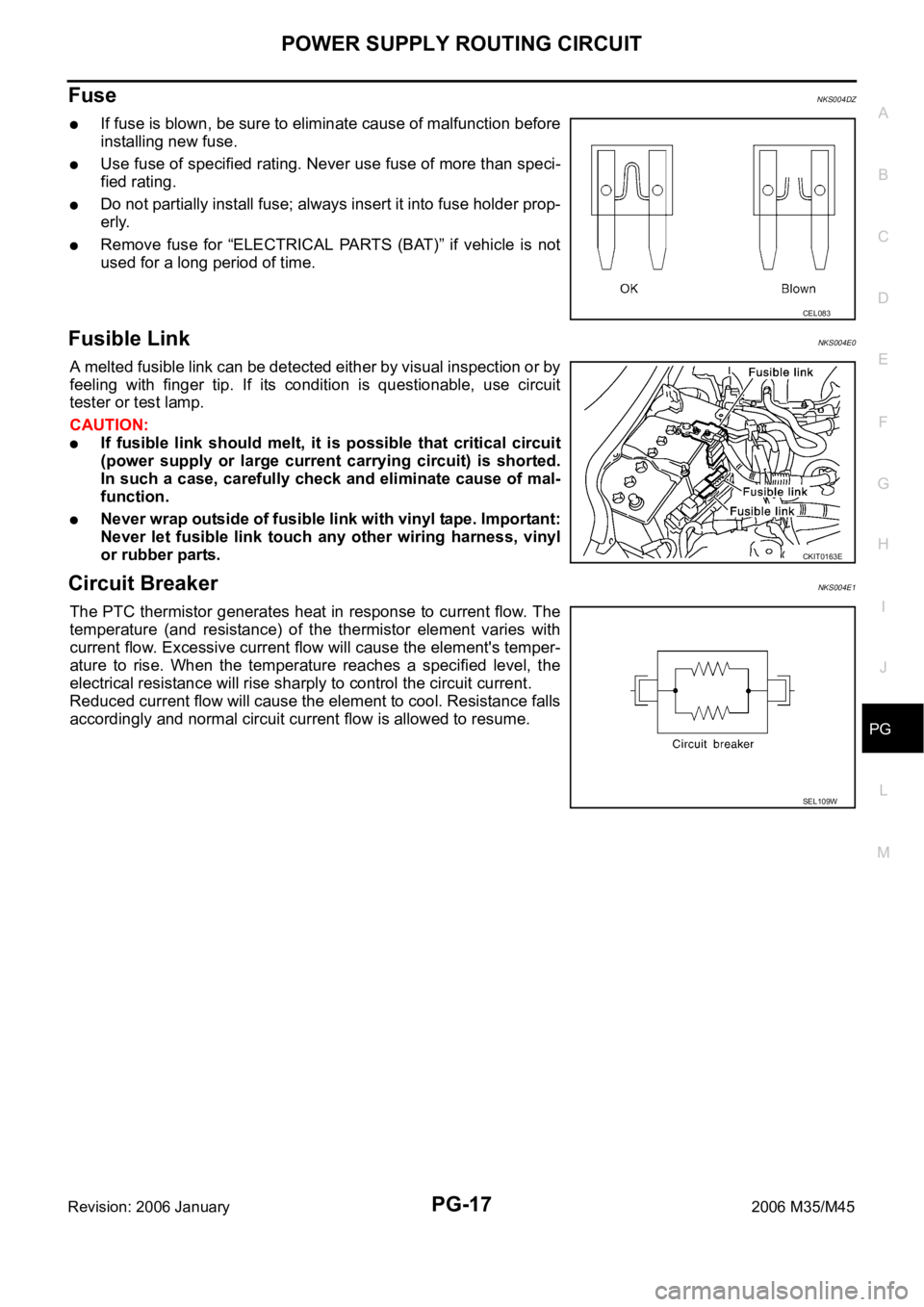
Fusible Link NKS004E0
A melted fusible link can be detected either by visual inspection or by
feeling with finger tip. If its condition is questionable, use circuit
tester or test lamp.
CAUTION:
If fusible link should melt, it is possible that critical circuit
(power supply or large current carrying circuit) is shorted.
In such a case, carefully check and eliminate cause of mal-
function.
Never wrap outside of fusible link with vinyl tape. Important:
Never let fusible link touch any other wiring harness, vinyl
or rubber parts.
Circuit Breaker NKS004E1
The PTC thermistor generates heat in response to current flow. The
temperature (and resistance) of the thermistor element varies with
current flow. Excessive current flow will cause the element's temper-
ature to rise. When the temperature reaches a specified level, the
electrical resistance will rise sharply to control the circuit current.
Reduced current flow will cause the element to cool. Resistance falls
accordingly and normal circuit current flow is allowed to resume.
CEL083
CKIT0163E
SEL109W
Page 4857 of 5621

PG-30
IPDM E/R (INTELLIGENT POWER DISTRIBUTION MODULE ENGINE ROOM)
Revision: 2006 January2006 M35/M45
Check IPDM E/R Power Supply and Ground CircuitNKS004EA
1. CHECK FUSE AND FUSIBLE LINK
Check for blown fuses.
OK or NG
OK >> GO TO 2.
NG >> If fuse or fusible link is blown, be sure to eliminate cause of malfunction before installing new fuse
or fusible link.
2. CHECK POWER SUPPLY CIRCUIT
1. Turn ignition switch OFF.
2. Disconnect IPDM E/R harness connector.
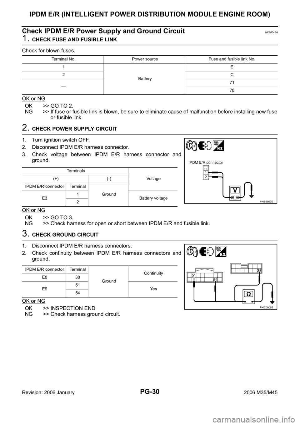
3. Check voltage between IPDM E/R harness connector and
ground.
OK or NG
OK >> GO TO 3.
NG >> Check harness for open or short between IPDM E/R and fusible link.
3. CHECK GROUND CIRCUIT
1. Disconnect IPDM E/R harness connectors.
2. Check continuity between IPDM E/R harness connectors and
ground.
OK or NG
OK >> INSPECTION END
NG >> Check harness ground circuit.
Terminal No. Power source Fuse and fusible link No.
1
BatteryE
2C
—71
78
Terminals
Vo l ta g e (+) (-)
IPDM E/R connector Terminal
Ground
E31
Battery voltage
2
PKIB6562E
IPDM E/R connector Terminal
GroundContinuity
E8 38
E951
Ye s
54
PKIC0906E
Page 4858 of 5621

IPDM E/R (INTELLIGENT POWER DISTRIBUTION MODULE ENGINE ROOM)
PG-31
C
D
E
F
G
H
I
J
L
MA
B
PG
Revision: 2006 January2006 M35/M45
Inspection with CONSULT-II (Self-Diagnosis)NKS004EB
CAUTION:
If CONSULT-II is used with no connection of CONSULT-II CONVERTER, malfunctions might be
detected in self-diagnosis depending on control unit which carry out CAN communication.
1. CHECK SELF DIAGNOSTIC RESULT
1. Connect CONSULT-II and select “IPDM E/R” on the “SELECT SYSTEM” screen.
2. Select “SELF-DIAG RESULTS” on the “SELECT DIAG MODE” screen.
3. Check display content in self diagnostic results.
NOTE:
The details for display of the period are as follows:
CRNT: Error currently detected with IPDM E/R.
PAST: Error detected in the past and memorized with IPDM E/R.
Contents displayed
NO DTC IS DETECTED.FURTHER TESTING MAY BE REQUIRED.>>INSPECTION END
CAN COMM CIRC>>After print-out of the monitor items, refer to LAN-7, "
Precautions When Using CON-
SULT-II" .
Removal and Installation of IPDM E/RNKS004EC
: Vehicle front
REMOVAL
1. Remove cowl top cover (RH). Refer to EI-18, "COWL TOP" in
“EI” section.
2. Disengage pawls (A) 4 on both side of IPDM E/R cover B (1),
remove IPDM E/R cover A (2).
3. While pushing pawl (A) on backside of IPDM E/R cover B (1)
toward vehicle front to unlock, lift up IPDM E/R (2).
CONSULT-II displayCONSULT-II
display codeTIME
Details of diagnosis result
CRNT PAST
NO DTC IS DETECTED.
FURTHER TESTING MAY BE REQUIRED.- - - No malfunction
CAN COMM CIRC U1000
Any of or several items below have errors.
TRANSMIT DIAG
ECM
BCM/SEC
SKIB4109E
SKIB4110E
Page 4859 of 5621

PG-32
IPDM E/R (INTELLIGENT POWER DISTRIBUTION MODULE ENGINE ROOM)
Revision: 2006 January2006 M35/M45
4. Disengage pawls on both side of IPDM E/R (1), remove IPDM E/
R cover B.
5. Remove harness connector from IPDM E/R (1) and remove
IPDM E/R (1).
INSTALLATION
Installation is the reverse order of removal.
SKIB4111E
Page 4861 of 5621

PG-34
PDU (POWER DISTRIBUTION UNIT)
Revision: 2006 January2006 M35/M45
*1: When the A/T selector lever position is N position, the engine start condition is different according to the vehicle speed.
At vehicle speed of 5 km/h or less, the engine can start only when the brake pedal is depressed.
At vehicle speed of 5 km/h or more, the engine can start even if the brake pedal is not depressed. (It is the same as “Engine stall
return operation while driving”.)
*2: When the A/T selector lever position is any position other than P position and when the vehicle speed is 5 km/h or more, the engine
stop condition is different.
Press and hold the push-button ignition switch for 2 seconds or more. (When the push-button ignition switch is pressed for too short
a time, the operation may be invalid, so properly press and hold to prevent the incorrect operation.)
Press the push-button ignition switch 3 times within 1.5 seconds. (Emergency stop operation) Power supply positionEngine start/stop condition Push-button ignition
switch operation fre-
quency Brake pedal operation condition A/T selector lever position
LOCK
ACCNot depressed
(When A/T selector lever is in any posi-
tion other than P or N, there will be no
effect even if it is depressed.)Any position other than P or N
(When the brake pedal is not
depressed, there will be no effect even
if the A/T selector lever is in P or N
position.)1
LOCK
ACC ONNot depressed
(When A/T selector lever is in any posi-
tion other than P or N, there will be no
effect even if it is depressed.)Any position other than P or N
(When the brake pedal is not
depressed, there will be no effect even
if the A/T selector lever is in P or N
position.)2
LOCK
ACC ON
LOCKNot depressed
(When A/T selector lever is in any posi-
tion other than P or N, there will be no
effect even if it is depressed.)Any position other than P or N
(When the brake pedal is not
depressed, there will be no effect even
if the A/T selector lever is in P or N
position.)3
LOCK
START
ACC
START
ON
START
(Engine start)Depressed P or N position (*1)1
[If the switch is
pushed once, the
engine starts from
any power supply
position (LOCK,
ACC, and ON)]
Engine start condition
LOCK
(Engine stop)— P position 1
Engine start condition
ACC
(Engine stop)— Any position other than P (*2) 1
Engine stall return
operation while driving— N position 1