2006 INFINITI M35 battery
[x] Cancel search: batteryPage 5526 of 5621

WT-1
ROAD WHEELS & TIRES
E SUSPENSION
CONTENTS
C
D
F
G
H
I
J
K
L
M
SECTION WT
A
B
WT
Revision: 2006 January2006 M35/M45
ROAD WHEELS & TIRES
PRECAUTIONS .......................................................... 3
Precautions .............................................................. 3
PREPARATION ........................................................... 4
Special Service Tools [SST] ..................................... 4
Commercial Service Tools ........................................ 4
NOISE, VIBRATION AND HARSHNESS (NVH)
TROUBLESHOOTING ................................................ 5
NVH Troubleshooting Chart ..................................... 5
ROAD WHEEL ............................................................ 6
Inspection ................................................................. 6
ALUMINUM WHEEL ............................................. 6
STEEL WHEEL ..................................................... 6
ROAD WHEEL TIRE ASSEMBLY .............................. 7
Balancing Wheels (Bonding Weight Type) ............... 7
REMOVAL ........................................................
..... 7
WHEEL BALANCE ADJUSTMENT ...................... 7
Rotation .................................................................... 8
LOW TIRE PRESSURE WARNING SYSTEM ............ 9
System Components ................................................ 9
System Description .................................................. 9
TRANSMITTER ..................................................... 9
RECEIVER .......................................................
... 10
LOW TIRE PRESSURE WARNING CONTROL
UNIT .................................................................... 10
LOW TIRE PRESSURE WARNING LAMP ......... 10
DISPLAY UNIT ..................................................... 11
CAN COMMUNICATION .......................................... 12
System Description ................................................ 12
TROUBLE DIAGNOSES .......................................... 13
How to Perform Trouble Diagnoses ....................... 13
BASIC CONCEPT ............................................... 13
Schematic .............................................................. 14
Wiring Diagram — T/WARN — .............................. 15
Control Unit Input/Output Signal Standard ............. 18
ID Registration Procedure ...................................... 19
ID REGISTRATION WITH ACTIVATION TOOL ... 19
ID REGISTRATION WITHOUT ACTIVATION
TOOL .................................................................. 20
Transmitter Wake Up Operation ............................. 21
WITH TRANSMITTER ACTIVATION TOOL ........ 21CONSULT-II Function (AIR PRESSURE MONI-
TOR) ....................................................................... 21
FUNCTION .......................................................
... 21
CONSULT-II SETTING PROCEDURE ................ 21
WORK SUPPORT MODE ................................... 22
SELF-DIAG RESULT MODE ............................... 22
DATA MONITOR MODE ...................................... 23
ACTIVE TEST MODE ......................................... 23
LOW TIRE PRESSURE WARNING CONTROL
UNIT PART NUMBER ......................................... 24
Diagnosis Procedure with Warning Lamp Function
(Without CONSULT-II) ............................................ 24
DESCRIPTION .................................................... 24
FUNCTION .......................................................
... 24
LOW TIRE PRESSURE WARNING LAMP DIAG-
NOSTIC CHART .................................................. 24
How to Perform Trouble Diagnosis for Quick and
Accurate Repair ...................................................... 26
INTRODUCTION ................................................. 26
WORK FLOW ...................................................... 26
Preliminary Check .................................................. 27
Trouble Diagnosis Chart ......................................... 28
SELF-DIAGNOSIS .............................................. 28
DIAGNOSIS CHART BY SYMPTOM .................. 29
TROUBLE DIAGNOSIS FOR SELF-DIAGNOSTIC
ITEMS ........................................................................ 30
Inspection 1: Transmitter no Data ........................... 30
MALFUNCTION CODE NO. 21, 22, 23, 24 ......... 30
Inspection 2: Receiver Data Error .......................... 31
MALFUNCTION CODE NO. 25, 26, 27, 28 ......... 31
Inspection 3: Transmitter Pressure Data Error ....... 32
MALFUNCTION CODE NO. 35, 36, 37, 38 ......... 32
Inspection 4: Transmitter Function Code Error ....... 32
MALFUNCTION CODE NO. 41, 42, 43, 44 ......... 32
Inspection 5: Transmitter Battery Voltage Low ....... 33
MALFUNCTION CODE NO. 45, 46, 47, 48 ......... 33
Inspection 6: Receiver ID No Registration .............. 33
MALFUNCTION CODE NO. 51 ........................... 33
Inspection 7: Vehicle Speed Signal ........................ 34
Page 5543 of 5621

WT-18
TROUBLE DIAGNOSES
Revision: 2006 January2006 M35/M45
Control Unit Input/Output Signal StandardNES000JX
CAUTION:
When checked using a circuit tester for voltage measurement, connector terminals should not be
forcefully extended.
Terminal
Measuring point Measuring condition Standard
+
(wire color)–
2 (B/R)
GroundIgnition switch Ignition switch ON Battery voltage (12 V)
5 (W/R)Tire pressure warning check
connectorAlways Approx. 5 V
7 (LG)
Battery power supply
Ignition switch ONBattery voltage (12 V) 8 (R/W)
9 (GY)
10 (SB)
11 (W/G)
Signal Input Approx. 4.5 V 12 (R)
13 (L)
14 (L/G)
15 (L) Data line (CAN-H) — —
16 (P) Data line (CAN-L) — —
17 (B) Ground — 0 V
19 (G/R) HazardHazard lamp switch OFF Battery voltage (Approx. 12 V)
Hazard lamp switch ON 0 V
23 (BR)
Ground
—0 V
24 (W/L) — 0 V
25 (B/R) — 0 V
26 (V) — 0 V
27 (O)
Analog signal Ignition switch ON Approx. 0.7 V 28 (G)
29 (P)
30 (L/R)
Page 5547 of 5621
WT-22
TROUBLE DIAGNOSES
Revision: 2006 January2006 M35/M45
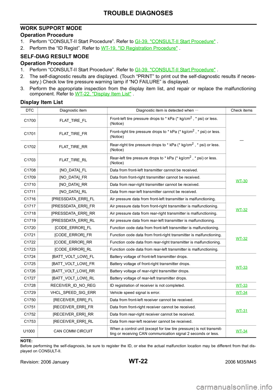
WORK SUPPORT MODE
Operation Procedure
1. Perform “CONSULT-II Start Procedure”. Refer to GI-39, "CONSULT-II Start Procedure" .
2. Perform the “ID Regist”. Refer to WT-19, "
ID Registration Procedure" .
SELF-DIAG RESULT MODE
Operation Procedure
1. Perform “CONSULT-II Start Procedure”. Refer to GI-39, "CONSULT-II Start Procedure" .
2. The self-diagnostic results are displayed. (Touch “PRINT” to print out the self-diagnostic results if neces-
sary.) Check low tire pressure warning lamp if “NO FAILURE” is displayed.
3. Perform the appropriate inspection from the display item list, and repair or replace the malfunctioning
component. Refer to WT-22, "
Display Item List" .
Display Item List
NOTE:
Before performing the self-diagnosis, be sure to register the ID, or else the actual malfunction location may be different from that dis-
played on CONSULT-II.DTC Diagnostic item Diagnostic item is detected when ꞏꞏꞏ Check items
C1700 FLAT_TIRE_FLFront-left tire pressure drops to * kPa (* kg/cm
2 , * psi) or less.
(Notice)
— C1701 FLAT_TIRE_FRFront-right tire pressure drops to * kPa (* kg/cm
2 , * psi) or less.
(Notice)
C1702 FLAT_TIRE_RRRear-right tire pressure drops to * kPa (* kg/cm
2 , * psi) or less.
(Notice)
C1703 FLAT_TIRE_RLRear-left tire pressure drops to * kPa (* kg/cm
2 , * psi) or less.
(Notice)
C1708 [NO_DATA]_FL Data from front-left transmitter cannot be received.
WT-30
C1709 [NO_DATA]_FR Data from front-right transmitter cannot be received.
C1710 [NO_DATA]_RR Data from rear-right transmitter cannot be received.
C1711 [NO_DATA]_RL Data from rear-left transmitter cannot be received.
C1716 [PRESSDATA_ERR]_FL Air pressure data from front-left transmitter is malfunctioning.
WT-32
C1717 [PRESSDATA_ERR]_FR Air pressure data from front-right transmitter is malfunctioning.
C1718 [PRESSDATA_ERR]_RR Air pressure data from rear-right transmitter is malfunctioning.
C1719 [PRESSDATA_ERR]_RL Air pressure data from rear-left transmitter is malfunctioning.
C1720 [CODE_ERROR]_FL Function code data from front-left transmitter is malfunctioning.
WT-32
C1721 [CODE_ERROR]_FR Function code data from front-right transmitter is malfunctioning.
C1722 [CODE_ERROR]_RR Function code data from rear-right transmitter is malfunctioning.
C1723 [CODE_ERROR]_RL Function code data from rear-left transmitter is malfunctioning.
C1724 [BATT_VOLT_LOW]_FL Battery voltage of front-left transmitter drops.
WT-33
C1725 [BATT_VOLT_LOW]_FR Battery voltage of front-right transmitter drops.
C1726 [BATT_VOLT_LOW]_RR Battery voltage of rear-right transmitter drops.
C1727 [BATT_VOLT_LOW]_RL Battery voltage of rear-left transmitter drops.
C1728 RECEIVER_ID_NO_REG ID registration of receiver is not completed.WT-33
C1729 VHCL_SPEED_SIG_ERR Vehicle speed signal is error.WT-34
C1750 [RECEIVER_ERR]_FL Data from front-left receiver cannot be received.
WT-31
C1751 [RECEIVER_ERR]_FR Data from front-right receiver cannot be received.
C1752 [RECEIVER_ERR]_RR Data from rear-right receiver cannot be received.
C1753 [RECEIVER_ERR]_RL Data from rear-left receiver cannot be received.
U1000 CAN COMM CIRCUITWhen a control unit (except for low tire pressure) is not transmit-
ting or receiving CAN communication signal 2 seconds or less. WT-34
Page 5550 of 5621
TROUBLE DIAGNOSES
WT-25
C
D
F
G
H
I
J
K
L
MA
B
WT
Revision: 2006 January2006 M35/M45
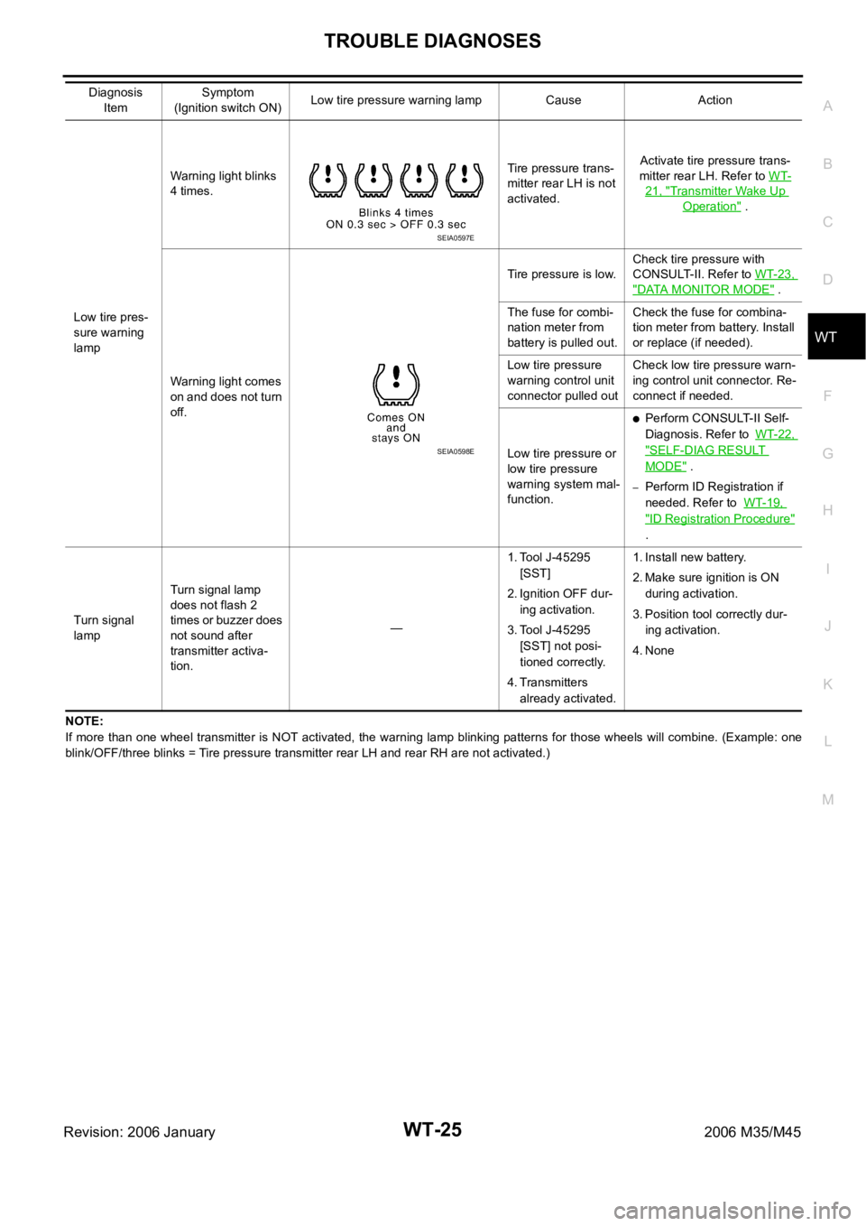
NOTE:
If more than one wheel transmitter is NOT activated, the warning lamp blinking patterns for those wheels will combine. (Example: one
blink/OFF/three blinks = Tire pressure transmitter rear LH and rear RH are not activated.) Low tire pres-
sure warning
lampWarning light blinks
4 times.Tire pressure trans-
mitter rear LH is not
activated.Activate tire pressure trans-
mitter rear LH. Refer to WT-
21, "Transmitter Wake Up
Operation" .
Warning light comes
on and does not turn
off.Tire pressure is low.Check tire pressure with
CONSULT-II. Refer to WT-23,
"DATA MONITOR MODE" .
The fuse for combi-
nation meter from
battery is pulled out.Check the fuse for combina-
tion meter from battery. Install
or replace (if needed).
Low tire pressure
warning control unit
connector pulled outCheck low tire pressure warn-
ing control unit connector. Re-
connect if needed.
Low tire pressure or
low tire pressure
warning system mal-
function.
Perform CONSULT-II Self-
Diagnosis. Refer to WT-22,
"SELF-DIAG RESULT
MODE" .
–Perform ID Registration if
needed. Refer to WT-19,
"ID Registration Procedure"
.
Turn signal
lampTurn signal lamp
does not flash 2
times or buzzer does
not sound after
transmitter activa-
tion.—1. Tool J-45295
[SST]
2. Ignition OFF dur-
ing activation.
3. Tool J-45295
[SST] not posi-
tioned correctly.
4. Transmitters
already activated.1. Install new battery.
2. Make sure ignition is ON
during activation.
3. Position tool correctly dur-
ing activation.
4. None Diagnosis
ItemSymptom
(Ignition switch ON)Low tire pressure warning lamp Cause Action
SEIA0597E
SEIA0598E
Page 5552 of 5621
TROUBLE DIAGNOSES
WT-27
C
D
F
G
H
I
J
K
L
MA
B
WT
Revision: 2006 January2006 M35/M45
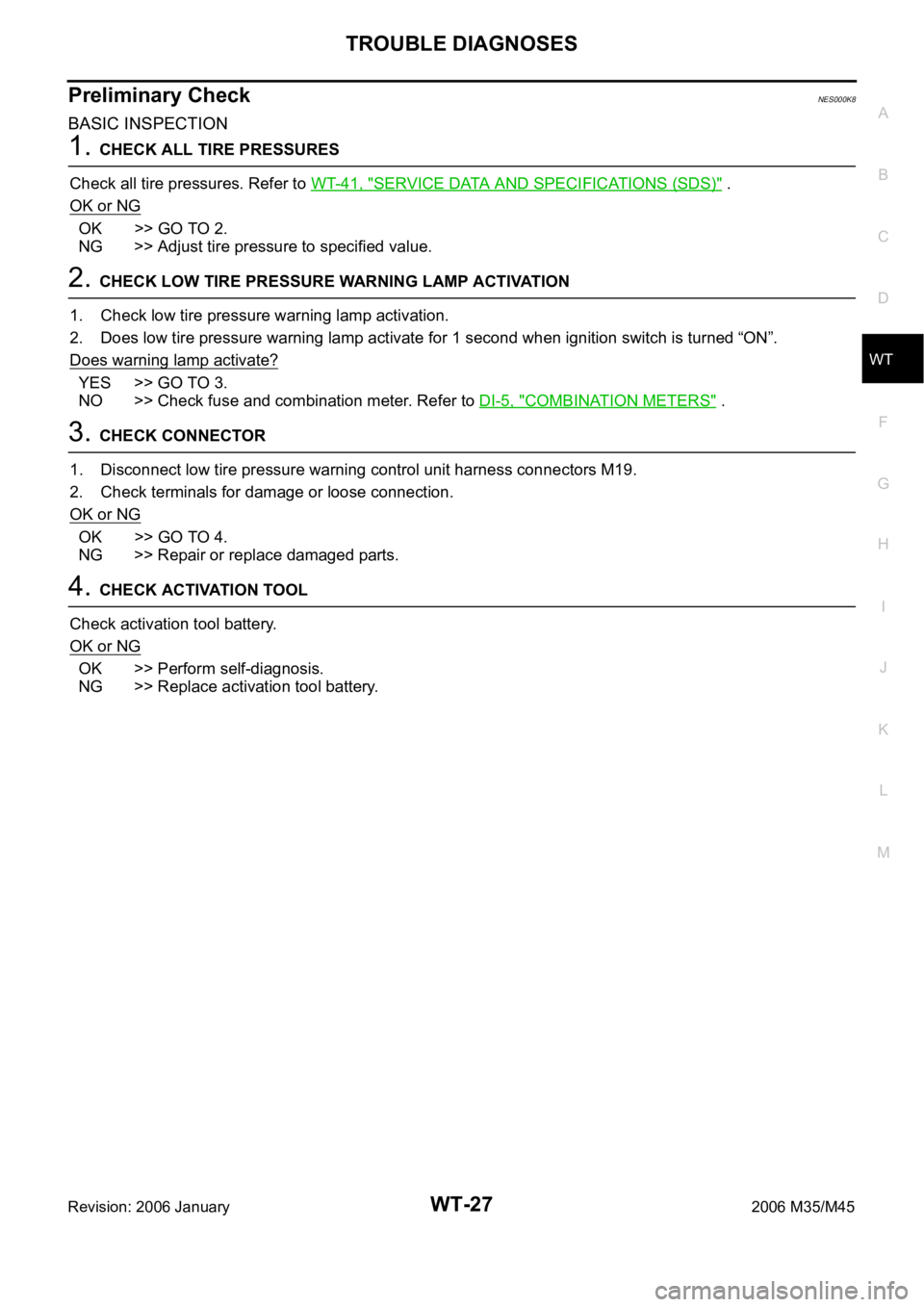
Preliminary CheckNES000K8
BASIC INSPECTION
1. CHECK ALL TIRE PRESSURES
Check all tire pressures. Refer to WT-41, "
SERVICE DATA AND SPECIFICATIONS (SDS)" .
OK or NG
OK >> GO TO 2.
NG >> Adjust tire pressure to specified value.
2. CHECK LOW TIRE PRESSURE WARNING LAMP ACTIVATION
1. Check low tire pressure warning lamp activation.
2. Does low tire pressure warning lamp activate for 1 second when ignition switch is turned “ON”.
Does warning lamp activate?
YES >> GO TO 3.
NO >> Check fuse and combination meter. Refer to DI-5, "
COMBINATION METERS" .
3. CHECK CONNECTOR
1. Disconnect low tire pressure warning control unit harness connectors M19.
2. Check terminals for damage or loose connection.
OK or NG
OK >> GO TO 4.
NG >> Repair or replace damaged parts.
4. CHECK ACTIVATION TOOL
Check activation tool battery.
OK or NG
OK >> Perform self-diagnosis.
NG >> Replace activation tool battery.
Page 5553 of 5621

WT-28
TROUBLE DIAGNOSES
Revision: 2006 January2006 M35/M45
Trouble Diagnosis ChartNES000K9
SELF-DIAGNOSIS
NOTICE:
186 kPa (1.86 kg/cm2 , 27 psi): Standard air pressure is for 230 kpa (2.3 kg/cm2 , 33 psi) vehicles. Item
Reference Self-diagnosis function CONSULT-II
DTC (warning lamp blinks) Diagnosis item Diagnosis item
11Front-left tire pressure drops to * kPa
(* kg/cm
2 , * psi) or less. (Notice)FLAT_TIRE_FL
— 12Front-right tire pressure drops to * kPa
(* kg/cm
2 , * psi) or less. (Notice)FLAT_TIRE_FR
13Rear-right tire pressure drops to * kPa
(* kg/cm
2 , * psi) or less. (Notice)FLAT_TIRE_RR
14Rear-left tire pressure drops to * kPa (*
kg/cm
2 , * psi) or less. (Notice)FLAT_TIRE_RL
21 Transmitter no data (front - left) [NO_DATA]_FL
WT-30
22 Transmitter no data (front - right) [NO_DATA]_FR
23 Transmitter no data (rear - right) [NO_DATA]_RR
24 Transmitter no data (rear - left) [NO_DATA]_RL
25 Receiver data error (front - left) [RECEIVER_ERR]_FL
WT-31
26 Receiver data error (front - right) [RECEIVER_ERR]_FR
27 Receiver data error (rear - right) [RECEIVER_ERR]_RR
28 Receiver data error (rear - left) [RECEIVER_ERR]_RL
35Transmitter pressure data error (front -
left)[PRESSDATA_ERR]_FL
WT-32
36Transmitter pressure data error (front -
right)[PRESSDATA_ERR]_FR
37Transmitter pressure data error (rear -
right)[PRESSDATA_ERR]_RR
38Transmitter pressure data error (rear -
left)[PRESSDATA_ERR]_RL
41Transmitter function code error (front -
left)[CODE_ERROR]_FL
WT-32
42Transmitter function code error (front -
right)[CODE_ERROR]_FR
43Transmitter function code error (rear -
right)[CODE_ERROR]_RR
44Transmitter function code error (rear -
left)[CODE_ERROR]_RL
45Transmitter battery voltage low (front -
left)[BATT_VOLT_LOW]_FL
WT-33
46Transmitter battery voltage low (front -
right)[BATT_VOLT_LOW]_FR
47Transmitter battery voltage low (rear -
right)[BATT_VOLT_LOW]_RR
48Transmitter battery voltage low (rear -
left)[BATT_VOLT_LOW]_RL
51 Receiver ID no registration RECEIVER_ID_NO_REGWT-33
52 Vehicle speed signal VHCL_SPED_SIG_ERRWT-34
— CAN COMM CIRCUITWT-34
Page 5556 of 5621
TROUBLE DIAGNOSIS FOR SELF-DIAGNOSTIC ITEMS
WT-31
C
D
F
G
H
I
J
K
L
MA
B
WT
Revision: 2006 January2006 M35/M45
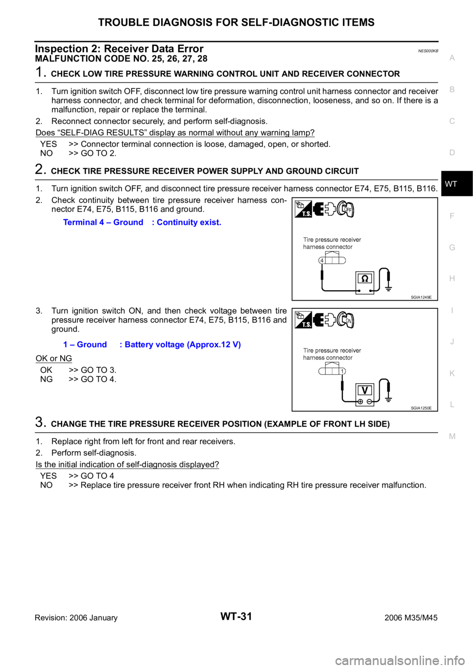
Inspection 2: Receiver Data ErrorNES000KB
MALFUNCTION CODE NO. 25, 26, 27, 28
1. CHECK LOW TIRE PRESSURE WARNING CONTROL UNIT AND RECEIVER CONNECTOR
1. Turn ignition switch OFF, disconnect low tire pressure warning control unit harness connector and receiver
harness connector, and check terminal for deformation, disconnection, looseness, and so on. If there is a
malfunction, repair or replace the terminal.
2. Reconnect connector securely, and perform self-diagnosis.
Does
“SELF-DIAG RESULTS” display as normal without any warning lamp?
YES >> Connector terminal connection is loose, damaged, open, or shorted.
NO >> GO TO 2.
2. CHECK TIRE PRESSURE RECEIVER POWER SUPPLY AND GROUND CIRCUIT
1. Turn ignition switch OFF, and disconnect tire pressure receiver harness connector E74, E75, B115, B116.
2. Check continuity between tire pressure receiver harness con-
nector E74, E75, B115, B116 and ground.
3. Turn ignition switch ON, and then check voltage between tire
pressure receiver harness connector E74, E75, B115, B116 and
ground.
OK or NG
OK >> GO TO 3.
NG >> GO TO 4.
3. CHANGE THE TIRE PRESSURE RECEIVER POSITION (EXAMPLE OF FRONT LH SIDE)
1. Replace right from left for front and rear receivers.
2. Perform self-diagnosis.
Is the initial indication of self-diagnosis displayed?
YES >> GO TO 4
NO >> Replace tire pressure receiver front RH when indicating RH tire pressure receiver malfunction. Terminal 4 – Ground : Continuity exist.
SGIA1249E
1 – Ground : Battery voltage (Approx.12 V)
SGIA1250E
Page 5558 of 5621
TROUBLE DIAGNOSIS FOR SELF-DIAGNOSTIC ITEMS
WT-33
C
D
F
G
H
I
J
K
L
MA
B
WT
Revision: 2006 January2006 M35/M45
2. REPLACE TIRE PRESSURE TRANSMITTER
1. Check low tire pressure warning condition again, and replace malfunctioning tire pressure transmitter.
2. Perform ID registration of all transmitter.
Can ID registration of all tire pressure transmitters be completed?
YES >> GO TO 3.
NO >> GO TO the inspection 1. Refer to WT-30, "
Inspection 1: Transmitter no Data" .
3. VEHICLE DRIVING
Drive at a speed of 40 km/h (25 MPH) or more for 3 minutes, and then drive the vehicle at any speed for 10
minutes. Then check all tire pressures with CONSULT-II “DATA MONITOR” within 5 minutes.
Does
“DATA MONITOR” display tire pressure as normal without any warning lamp?
YES >> INSPECTION END
NO >> Replace malfunctioning transmitter, and perform “Step 3” again.
Inspection 5: Transmitter Battery Voltage LowNES000KE
MALFUNCTION CODE NO. 45, 46, 47, 48
1. ID REGISTRATION (CORRECTION OF TRANSMITTER LOCATION)
1. Perform ID registration of all transmitters.
2. Drive at a speed of 40 km/h (25 MPH) or more for 3 minutes, and then drive the vehicle at any speed for
10 minutes.
>> GO TO 2.
2. REPLACE TIRE PRESSURE TRANSMITTER
1. Check low tire pressure warning lamp condition again, and replace malfunctioning tire pressure transmit-
ter.
2. Perform ID registration of all tire pressure transmitter.
Can ID registration of all tire pressure transmitters be completed?
YES >> GO TO 3.
NO >> GO TO the inspection 1. Refer to WT-30, "
Inspection 1: Transmitter no Data" .
3. VEHICLE DRIVING
Drive at a speed of 40 km/h (25 MPH) or more for 3 minutes, and then drive the vehicle at any speed for 10
minutes. Then check all tire pressures with CONSULT-II “DATA MONITOR” within 5 minutes.
Does
“DATA MONITOR” display tire pressure as normal without any warning lamp?
YES >> INSPECTION END
NO >> Replace malfunctioning transmitter, and perform “Step 3” again.
Inspection 6: Receiver ID No RegistrationNES000KF
MALFUNCTION CODE NO. 51
1. ID REGISTRATION
1. Perform ID registration of all tire pressure transmitters. Refer to WT-19, "
ID Registration Procedure" .
2. Drive at a speed of 40 km/h (25 MPH) or more for 3 minutes, and then drive the vehicle at any speed for
10 minutes.
>> GO TO 2.