2006 INFINITI M35 checking oil
[x] Cancel search: checking oilPage 4792 of 5621
ENGINE MAINTENANCE (VQ35DE ENGINE)
MA-15
C
D
E
F
G
H
I
J
K
MA
B
MA
Revision: 2006 January2006 M35/M45
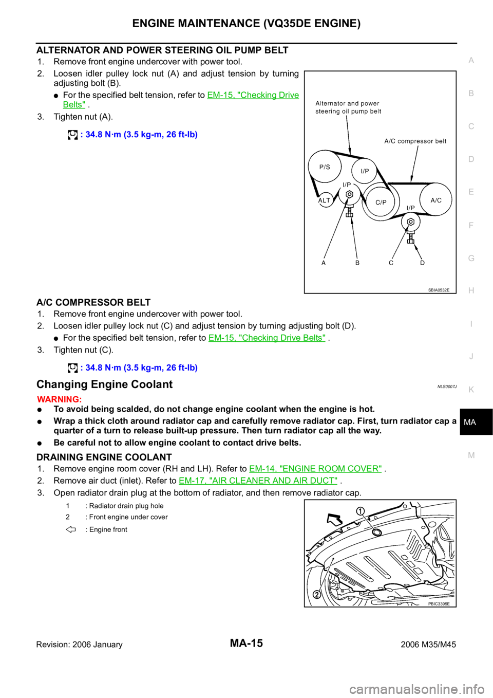
ALTERNATOR AND POWER STEERING OIL PUMP BELT
1. Remove front engine undercover with power tool.
2. Loosen idler pulley lock nut (A) and adjust tension by turning
adjusting bolt (B).
For the specified belt tension, refer to EM-15, "Checking Drive
Belts" .
3. Tighten nut (A).
A/C COMPRESSOR BELT
1. Remove front engine undercover with power tool.
2. Loosen idler pulley lock nut (C) and adjust tension by turning adjusting bolt (D).
For the specified belt tension, refer to EM-15, "Checking Drive Belts" .
3. Tighten nut (C).
Changing Engine CoolantNLS0007J
WAR NING :
To avoid being scalded, do not change engine coolant when the engine is hot.
Wrap a thick cloth around radiator cap and carefully remove radiator cap. First, turn radiator cap a
quarter of a turn to release built-up pressure. Then turn radiator cap all the way.
Be careful not to allow engine coolant to contact drive belts.
DRAINING ENGINE COOLANT
1. Remove engine room cover (RH and LH). Refer to EM-14, "ENGINE ROOM COVER" .
2. Remove air duct (inlet). Refer to EM-17, "
AIR CLEANER AND AIR DUCT" .
3. Open radiator drain plug at the bottom of radiator, and then remove radiator cap. : 34.8 Nꞏm (3.5 kg-m, 26 ft-lb)
SBIA0532E
: 34.8 Nꞏm (3.5 kg-m, 26 ft-lb)
1 : Radiator drain plug hole
2 : Front engine under cover
: Engine front
PBIC3395E
Page 4795 of 5621
MA-18
ENGINE MAINTENANCE (VQ35DE ENGINE)
Revision: 2006 January2006 M35/M45
Checking Fuel LinesNLS0007K
Inspect fuel lines, filler cap and tank for improper attachment, leaks,
cracks, damage, loose connections, chafing or deterioration.
If necessary, repair or replace damaged parts.
Changing Air Cleaner FilterNLS0007L
VISCOUS PAPER TYPE
The viscous paper type filter does not need cleaning between replacement intervals. Refer to MA-7,
"PERIODIC MAINTENANCE" .
Changing Engine OilNLS0007M
WAR NING :
Be careful not to burn yourself, as engine oil may be hot.
Prolonged and repeated contact with used engine oil may cause skin cancer; try to avoid direct
skin contact with used engine oil. If skin contact is made, wash thoroughly with soap or hand
cleaner as soon as possible.
1. Warm up the engine, and check for engine oil leakage from engine components. Refer to LU-7, "
ENGINE
OIL LEAKAGE" .
2. Stop the engine and wait for 10 minutes.
3. Loosen oil filler cap.
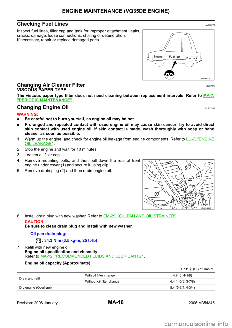
4. Remove mounting bolts, and then pull down the rear of front
engine under cover (1) and secure it using clip.
5. Remove drain plug (2) and then drain engine oil.
6. Install drain plug with new washer. Refer to EM-29, "
OIL PAN AND OIL STRAINER" .
CAUTION:
Be sure to clean drain plug and install with new washer.
7. Refill with new engine oil.
Engine oil specification and viscosity:
Refer to MA-12, "
RECOMMENDED FLUIDS AND LUBRICANTS" .
Engine oil capacity (Approximate):
Unit: (US qt, lmp qt)
SMA803A
KBIA3593J
Oil pan drain plug:
: 34.3 Nꞏm (3.5 kg-m, 25 ft-lb)
Drain and refill With oil filter change 4.7 (5, 4-1/8)
Without oil filter change 4.4 (4-5/8, 3-7/8)
Dry engine (Overhaul)5.4 (5-3/4, 4-3/4)
Page 4799 of 5621
MA-22
ENGINE MAINTENANCE (VK45DE ENGINE)
Revision: 2006 January2006 M35/M45
ENGINE MAINTENANCE (VK45DE ENGINE)PFP:10001
Checking Drive BeltsNLS0007Q
WAR NING :
Be sure to perform when the engine is stopped.
Remove air duct (inlet) when inspecting drive belt for alternator, water pump and A/C compressor.
Remove front engine undercover with power tool when inspecting power steering oil pump belt.
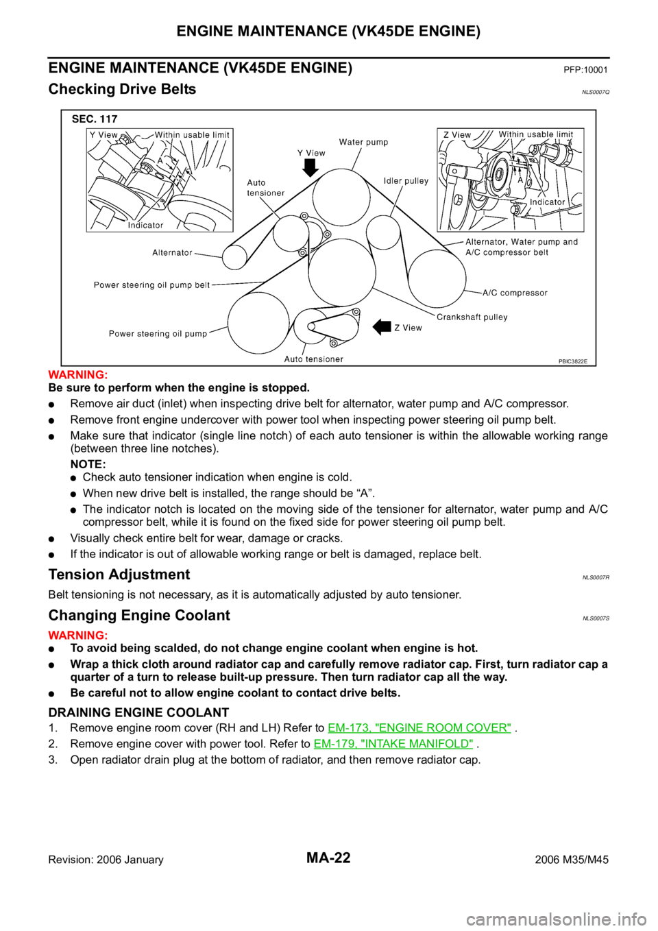
Make sure that indicator (single line notch) of each auto tensioner is within the allowable working range
(between three line notches).
NOTE:
Check auto tensioner indication when engine is cold.
When new drive belt is installed, the range should be “A”.
The indicator notch is located on the moving side of the tensioner for alternator, water pump and A/C
compressor belt, while it is found on the fixed side for power steering oil pump belt.
Visually check entire belt for wear, damage or cracks.
If the indicator is out of allowable working range or belt is damaged, replace belt.
Te n s i o n A d j u s t m e n tNLS0007R
Belt tensioning is not necessary, as it is automatically adjusted by auto tensioner.
Changing Engine CoolantNLS0007S
WAR NING :
To avoid being scalded, do not change engine coolant when engine is hot.
Wrap a thick cloth around radiator cap and carefully remove radiator cap. First, turn radiator cap a
quarter of a turn to release built-up pressure. Then turn radiator cap all the way.
Be careful not to allow engine coolant to contact drive belts.
DRAINING ENGINE COOLANT
1. Remove engine room cover (RH and LH) Refer to EM-173, "ENGINE ROOM COVER" .
2. Remove engine cover with power tool. Refer to EM-179, "
INTAKE MANIFOLD" .
3. Open radiator drain plug at the bottom of radiator, and then remove radiator cap.
PBIC3822E
Page 4802 of 5621
ENGINE MAINTENANCE (VK45DE ENGINE)
MA-25
C
D
E
F
G
H
I
J
K
MA
B
MA
Revision: 2006 January2006 M35/M45
4. Run engine and warm it up to normal operating temperature.
5. Rev engine two or three times under no-load.
6. Stop engine and wait until it cools down.
7. Drain water from the system. Refer to CO-40, "
DRAINING ENGINE COOLANT" .
8. Repeat steps 1 through 7 until clear water begins to drain from radiator.
Checking Fuel LinesNLS0007T
Inspect fuel lines, fuel filler cap and fuel tank for improper attach-
ment, leaks, cracks, damage, loose connections, chafing or deterio-
ration.
If necessary, repair or replace damaged parts.
Changing Air Cleaner FilterNLS0007U
VISCOUS PAPER TYPE
The viscous paper type filter does not need cleaning between replacement intervals. Refer to MA-7,
"PERIODIC MAINTENANCE" .
Changing Engine OilNLS0007V
WAR NING :
Be careful not to burn yourself, as engine oil may be hot.
Prolonged and repeated contact with used engine oil may cause skin cancer; try to avoid direct
skin contact with used engine oil. If skin contact is made, wash thoroughly with soap or hand
cleaner as soon as possible.
1. Warm up engine, put vehicle horizontally and check for engine oil leakage from engine components. Refer
to LU-26, "
ENGINE OIL LEAKAGE" .
2. Stop engine and wait for 15 minutes.
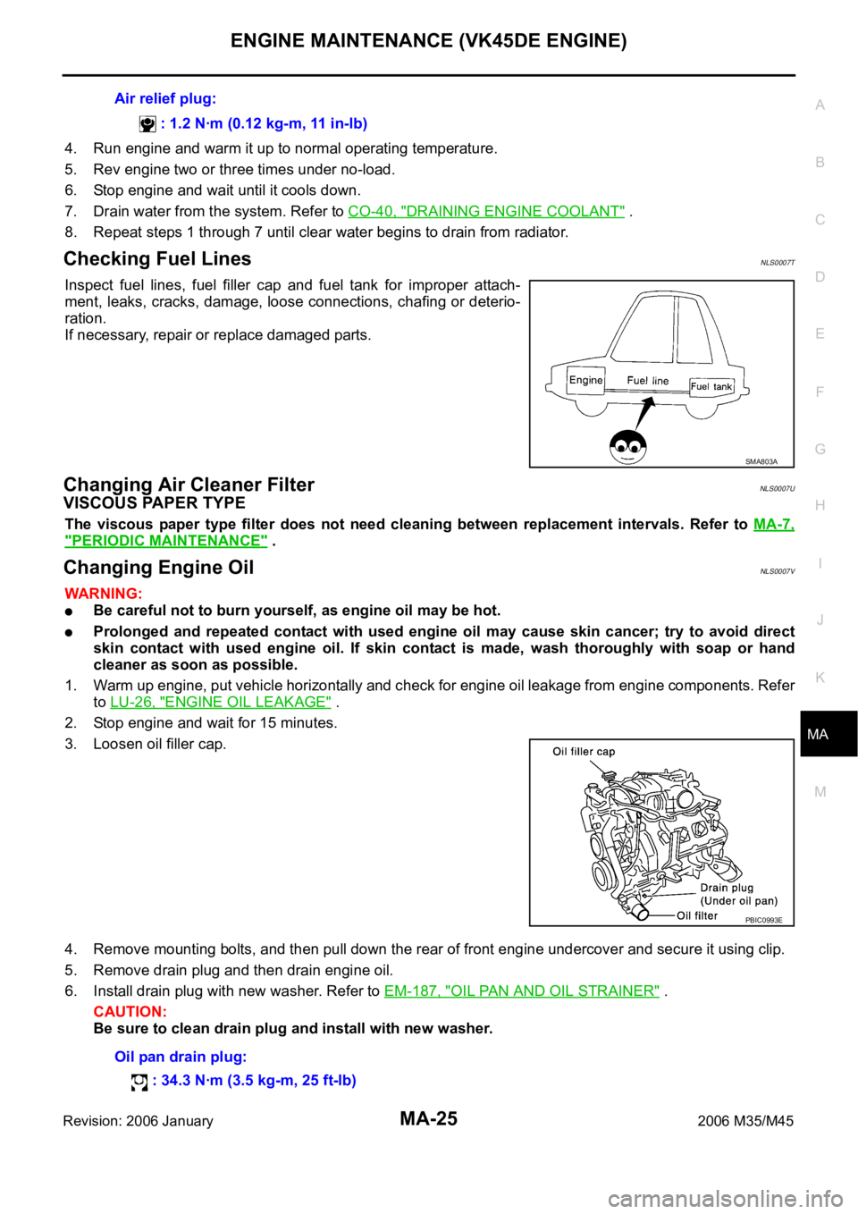
3. Loosen oil filler cap.
4. Remove mounting bolts, and then pull down the rear of front engine undercover and secure it using clip.
5. Remove drain plug and then drain engine oil.
6. Install drain plug with new washer. Refer to EM-187, "
OIL PAN AND OIL STRAINER" .
CAUTION:
Be sure to clean drain plug and install with new washer.Air relief plug:
: 1.2 Nꞏm (0.12 kg-m, 11 in-lb)
SMA803A
PBIC0993E
Oil pan drain plug:
: 34.3 Nꞏm (3.5 kg-m, 25 ft-lb)
Page 4809 of 5621
MA-32
CHASSIS AND BODY MAINTENANCE
Revision: 2006 January2006 M35/M45
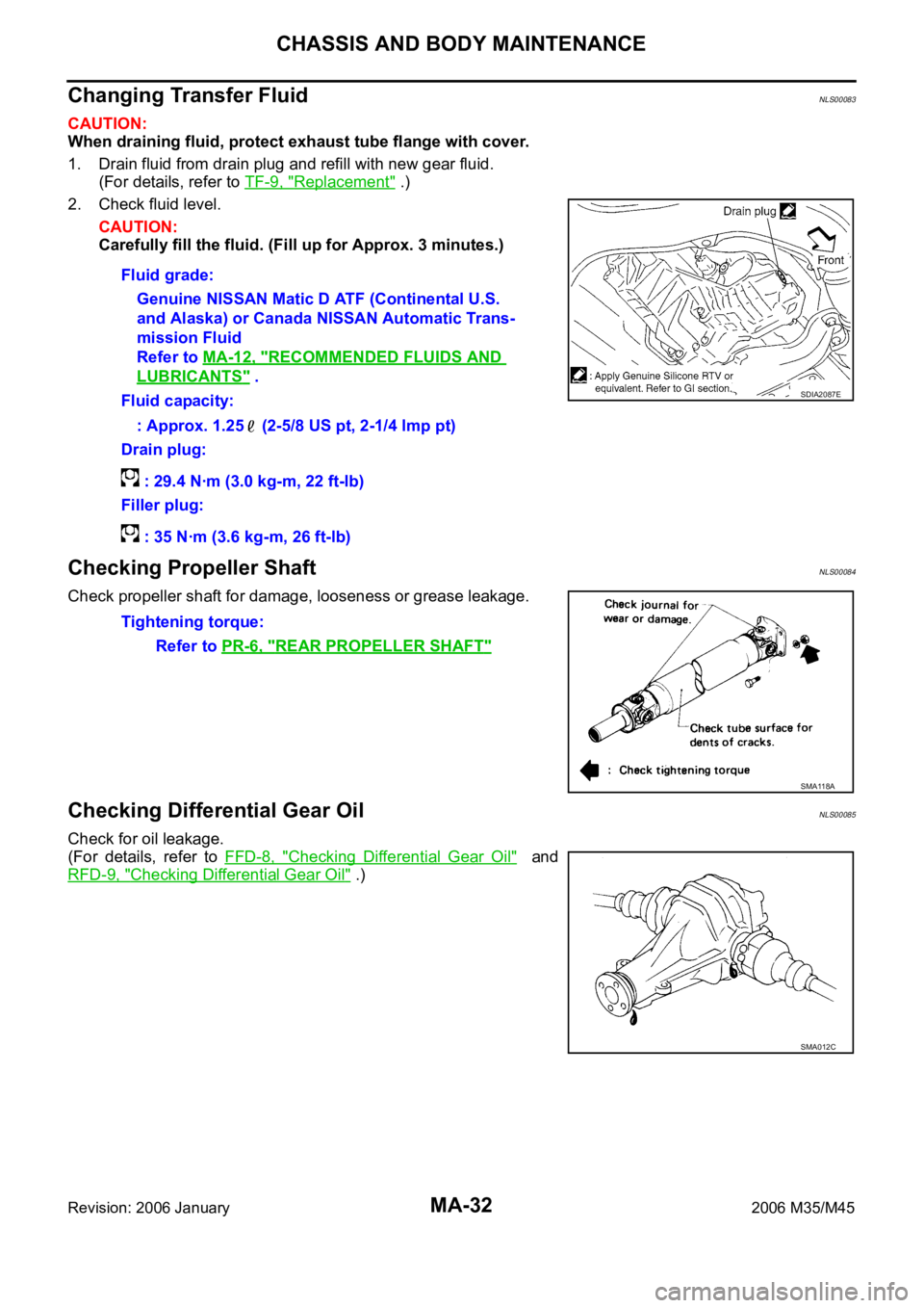
Changing Transfer FluidNLS00083
CAUTION:
When draining fluid, protect exhaust tube flange with cover.
1. Drain fluid from drain plug and refill with new gear fluid.
(For details, refer to TF-9, "
Replacement" .)
2. Check fluid level.
CAUTION:
Carefully fill the fluid. (Fill up for Approx. 3 minutes.)
Checking Propeller ShaftNLS00084
Check propeller shaft for damage, looseness or grease leakage.
Checking Differential Gear OilNLS00085
Check for oil leakage.
(For details, refer to FFD-8, "
Checking Differential Gear Oil" and
RFD-9, "
Checking Differential Gear Oil" .) Fluid grade:
Genuine NISSAN Matic D ATF (Continental U.S.
and Alaska) or Canada NISSAN Automatic Trans-
mission Fluid
Refer to MA-12, "
RECOMMENDED FLUIDS AND
LUBRICANTS" .
Fluid capacity:
: Approx. 1.25 (2-5/8 US pt, 2-1/4 lmp pt)
Drain plug:
: 29.4 Nꞏm (3.0 kg-m, 22 ft-lb)
Filler plug:
: 35 Nꞏm (3.6 kg-m, 26 ft-lb)SDIA2087E
Tightening torque:
Refer to PR-6, "
REAR PROPELLER SHAFT"
SMA118A
SMA012C
Page 4814 of 5621
CHASSIS AND BODY MAINTENANCE
MA-37
C
D
E
F
G
H
I
J
K
MA
B
MA
Revision: 2006 January2006 M35/M45
Checking Power Steering Fluid and LinesNLS0008E
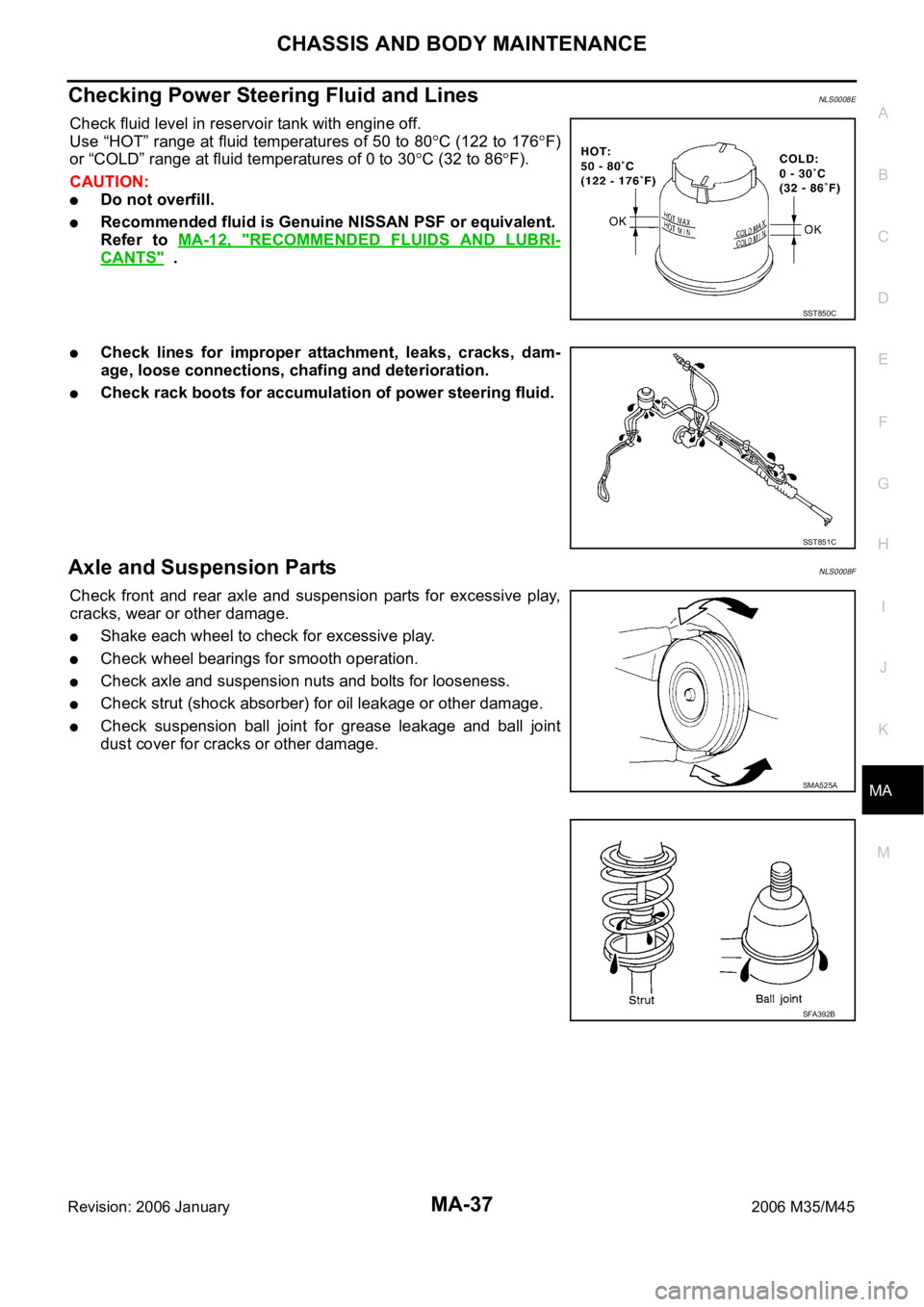
Check fluid level in reservoir tank with engine off.
Use “HOT” range at fluid temperatures of 50 to 80
C (122 to 176F)
or “COLD” range at fluid temperatures of 0 to 30
C (32 to 86F).
CAUTION:
Do not overfill.
Recommended fluid is Genuine NISSAN PSF or equivalent.
Refer to MA-12, "
RECOMMENDED FLUIDS AND LUBRI-
CANTS" .
Check lines for improper attachment, leaks, cracks, dam-
age, loose connections, chafing and deterioration.
Check rack boots for accumulation of power steering fluid.
Axle and Suspension PartsNLS0008F
Check front and rear axle and suspension parts for excessive play,
cracks, wear or other damage.
Shake each wheel to check for excessive play.
Check wheel bearings for smooth operation.
Check axle and suspension nuts and bolts for looseness.
Check strut (shock absorber) for oil leakage or other damage.
Check suspension ball joint for grease leakage and ball joint
dust cover for cracks or other damage.
SST850C
SST851C
SMA525A
SFA392B
Page 4816 of 5621
CHASSIS AND BODY MAINTENANCE
MA-39
C
D
E
F
G
H
I
J
K
MA
B
MA
Revision: 2006 January2006 M35/M45
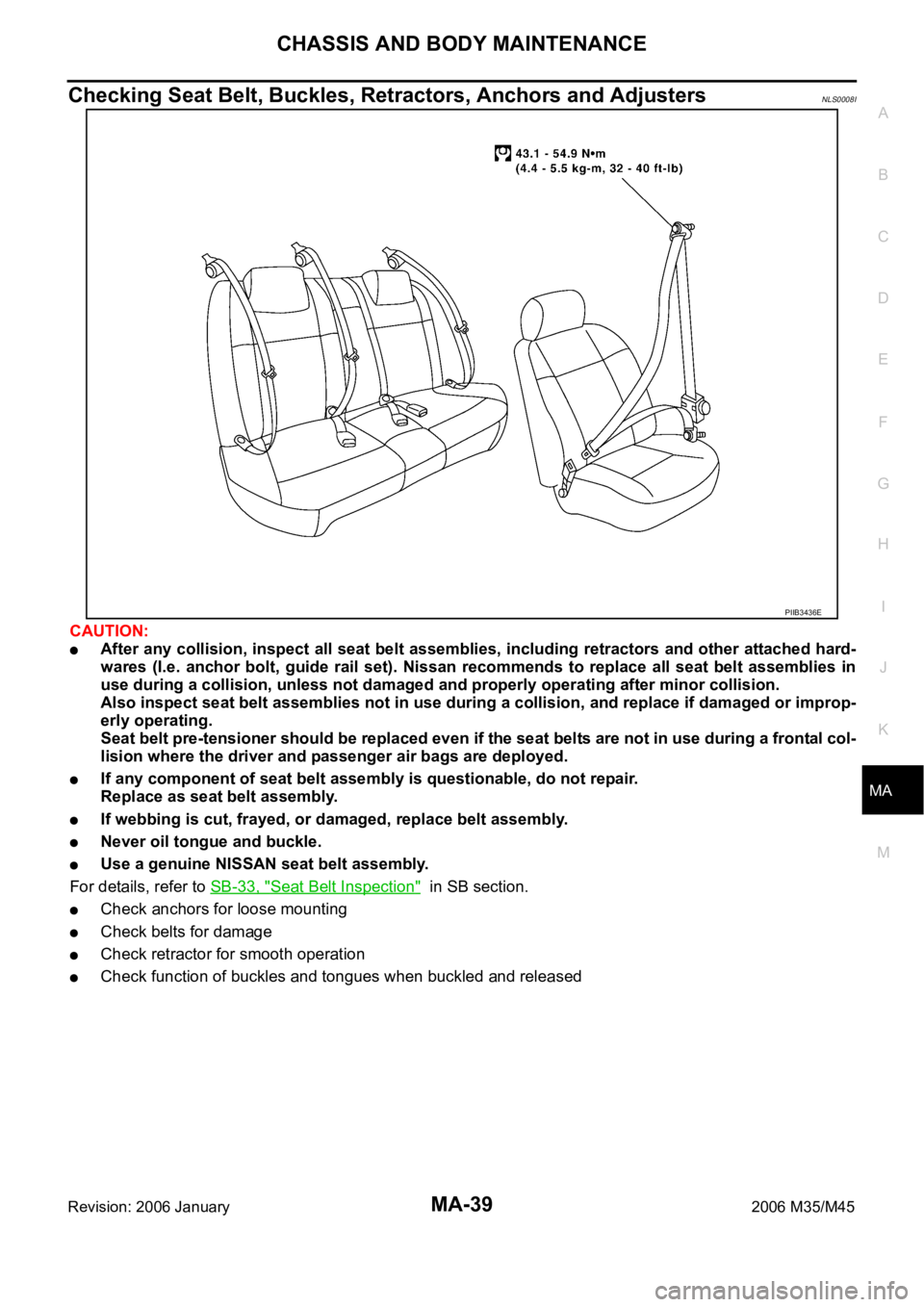
Checking Seat Belt, Buckles, Retractors, Anchors and AdjustersNLS0008I
CAUTION:
After any collision, inspect all seat belt assemblies, including retractors and other attached hard-
wares (I.e. anchor bolt, guide rail set). Nissan recommends to replace all seat belt assemblies in
use during a collision, unless not damaged and properly operating after minor collision.
Also inspect seat belt assemblies not in use during a collision, and replace if damaged or improp-
erly operating.
Seat belt pre-tensioner should be replaced even if the seat belts are not in use during a frontal col-
lision where the driver and passenger air bags are deployed.
If any component of seat belt assembly is questionable, do not repair.
Replace as seat belt assembly.
If webbing is cut, frayed, or damaged, replace belt assembly.
Never oil tongue and buckle.
Use a genuine NISSAN seat belt assembly.
For details, refer to SB-33, "
Seat Belt Inspection" in SB section.
Check anchors for loose mounting
Check belts for damage
Check retractor for smooth operation
Check function of buckles and tongues when buckled and released
PIIB3436E
Page 4954 of 5621
PS-1
POWER STEERING SYSTEM
G STEERING
CONTENTS
C
D
E
F
H
I
J
K
L
M
SECTION PS
A
B
PS
Revision: 2006 January2006 M35/M45
POWER STEERING SYSTEM
PRECAUTIONS .......................................................... 3
Precautions for Supplemental Restraint System
(SRS) “AIR BAG” and “SEAT BELT PRE-TEN-
SIONER” .................................................................. 3
Precautions Necessary for Steering Wheel Rotation
after Battery Disconnect ........................................... 3
OPERATION PROCEDURE ................................. 3
Precautions for Steering System .............................. 4
PREPARATION ........................................................... 5
Special Service Tools [SST] ..................................... 5
Commercial Service Tools ........................................ 6
NOISE, VIBRATION AND HARSHNESS (NVH)
TROUBLESHOOTING ................................................ 7
NVH Trouble Shooting Chart .................................... 7
POWER STEERING FLUID ........................................ 8
Checking Fluid Level ...........................................
..... 8
Checking Fluid Leakage ........................................... 8
Air Bleeding Hydraulic System ................................. 8
STEERING WHEEL .................................................. 10
On-Vehicle Inspection and Service ........................ 10
CHECKING CONDITION OF INSTALLATION .... 10
CHECKING STEERING WHEEL PLAY .............. 10
CHECKING NEUTRAL POSITION STEERING
WHEEL ............................................................... 10
CHECKING STEERING WHEEL TURNING
FORCE ................................................................ 10
CHECKING FRONT WHEEL TURNING ANGLE .... 11
Removal and Installation ........................................ 12
REMOVAL ........................................................
... 12
INSTALLATION ................................................... 12
STEERING COLUMN ............................................... 13
Removal and Installation ........................................ 13
COMPONENTS .................................................. 13
REMOVAL OF UPPER JOINT, COLLAR, HOLE
COVER SEAL, HOLE COVER, LOWER SHAFT
AND LOWER JOINT ........................................... 14
INSPECTION AFTER REMOVAL ....................... 14INSTALLATION OF UPPER JOINT, COLLAR,
HOLE COVER SEAL, HOLE COVER, LOWER
SHAFT AND LOWER JOINT .............................. 14
REMOVAL OF STEERING COLUMN ASSEM-
BLY ...................................................................... 15
INSPECTION AFTER REMOVAL ....................... 16
INSTALLATION OF STEERING COLUMN
ASSEMBLY ......................................................... 16
INSPECTION AFTER INSTALLATION ................ 16
Disassembly and Assembly .................................... 17
COMPONENTS ................................................... 17
DISASSEMBLY ................................................... 17
INSPECTION AFTER DISASSEMBLY ................ 17
ASSEMBLY ......................................................... 17
INSPECTION AFTER ASSEMBLY ...................... 17
POWER STEERING GEAR ...................................... 18
Removal and Installation ........................................ 18
COMPONENTS ................................................... 18
REMOVAL ........................................................
... 18
INSTALLATION ................................................... 19
INSPECTION AFTER INSTALLATION ................ 19
Disassembly and Assembly .................................
... 20
COMPONENTS ................................................... 20
DISASSEMBLY ................................................... 21
INSPECTION AFTER DISASSEMBLY ................ 22
ASSEMBLY ......................................................... 24
POWER STEERING OIL PUMP ............................... 29
On-Vehicle Inspection and Service ......................... 29
CHECKING RELIEF OIL PRESSURE ................ 29
Removal and Installation ........................................ 29
REMOVAL ........................................................
... 29
INSTALLATION ................................................... 29
Disassembly and Assembly (Models with VK45DE) ... 30
COMPONENTS ................................................... 30
INSPECTION BEFORE DISASSEMBLY ............. 30
DISASSEMBLY ................................................... 31
INSPECTION AFTER DISASSEMBLY ................ 31