Page 1482 of 4462
EC-98
[VQ35DE]
TROUBLE DIAGNOSIS
Revision: 2006 December 2006 FX35/FX45
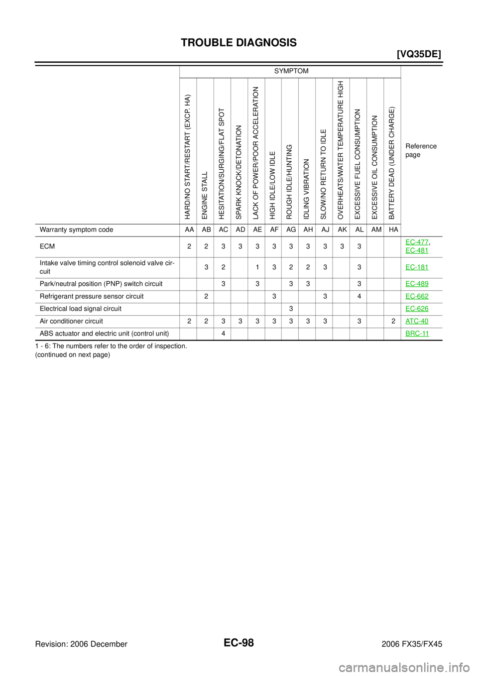
1 - 6: The numbers refer to the order of inspection.
(continued on next page) ECM 22333333333
EC-477
,
EC-481
Intake valve timing control solenoid valve cir-
cuit 32 13223 3
EC-181
Park/neutral position (PNP) switch circuit 3 3 3 3 3 EC-489
Refrigerant pressure sensor circuit 2 3 3 4EC-662
Electrical load signal circuit 3EC-626
Air conditioner circuit 223333333 3 2AT C - 4 0
ABS actuator and electric unit (control unit) 4BRC-11
SYMPTOM
Reference
page
HARD/NO START/RESTART (EXCP. HA)
ENGINE STALL
HESITATION/SURGING/FLAT SPOT
SPARK KNOCK/DETONATION
LACK OF POWER/POOR ACCELERATION
HIGH IDLE/LOW IDLE
ROUGH IDLE/HUNTING
IDLING VIBRATION
SLOW/NO RETURN TO IDLE
OVERHEATS/WATER TEMPERATURE HIGH
EXCESSIVE FUEL CONSUMPTION
EXCESSIVE OIL CONSUMPTION
BATTERY DEAD (UNDER CHARGE)
Warranty symptom code AA AB AC AD AE AF AG AH AJ AK AL AM HA
Page 1483 of 4462
TROUBLE DIAGNOSIS EC-99
[VQ35DE]
C
D E
F
G H
I
J
K L
M A
EC
Revision: 2006 December 2006 FX35/FX45
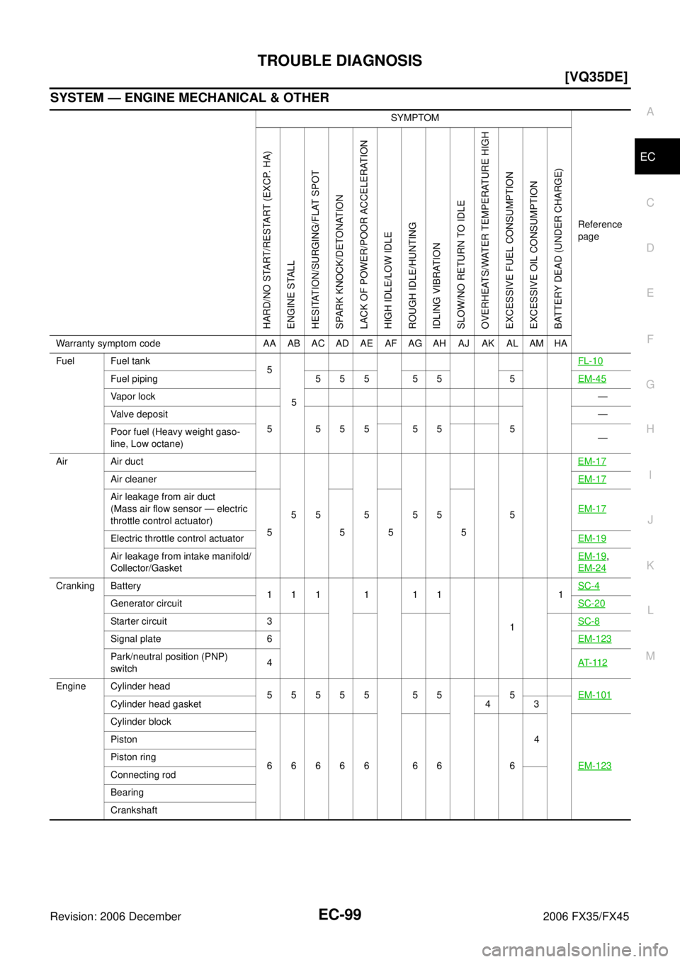
SYSTEM — ENGINE MECHANICAL & OTHER
SYMPTOM Reference
page
HARD/NO START/RESTART (EXCP. HA)
ENGINE STALL
HESITATION/SURGING/FLAT SPOT
SPARK KNOCK/DETONATION
LACK OF POWER/POOR ACCELERATION
HIGH IDLE/LOW IDLE
ROUGH IDLE/HUNTING
IDLING VIBRATION
SLOW/NO RETURN TO IDLE
OVERHEATS/WATER TEMPERATURE HIGH
EXCESSIVE FUEL CONSUMPTION
EXCESSIVE OIL CONSUMPTION
BATTERY DEAD (UNDER CHARGE)
Warranty symptom code AA AB AC AD AE AF AG AH AJ AK AL AM HA
Fuel Fuel tank 5
5 FL-10
Fuel piping 5 5 5 5 5 5
EM-45
Vapor lock —
Valve deposit 5 555 55 5 —
Poor fuel (Heavy weight gaso-
line, Low octane) —
Air Air duct
55555 5 EM-17
Air cleaner
EM-17
Air leakage from air duct
(Mass air flow sensor — electric
throttle control actuator) 5555 EM-17
Electric throttle control actuator
EM-19
Air leakage from intake manifold/
Collector/Gasket EM-19,
EM-24
Cranking Battery 111111
1 1
SC-4
Generator circuit
SC-20
Starter circuit 3SC-8
Signal plate 6EM-123
Park/neutral position (PNP)
switch 4
AT- 11 2
Engine Cylinder head
55555 55 5 EM-101
Cylinder head gasket 4 3
Cylinder block
66666 66 6 4
EM-123
Piston
Piston ring
Connecting rod
Bearing
Crankshaft
Page 1484 of 4462
EC-100
[VQ35DE]
TROUBLE DIAGNOSIS
Revision: 2006 December 2006 FX35/FX45
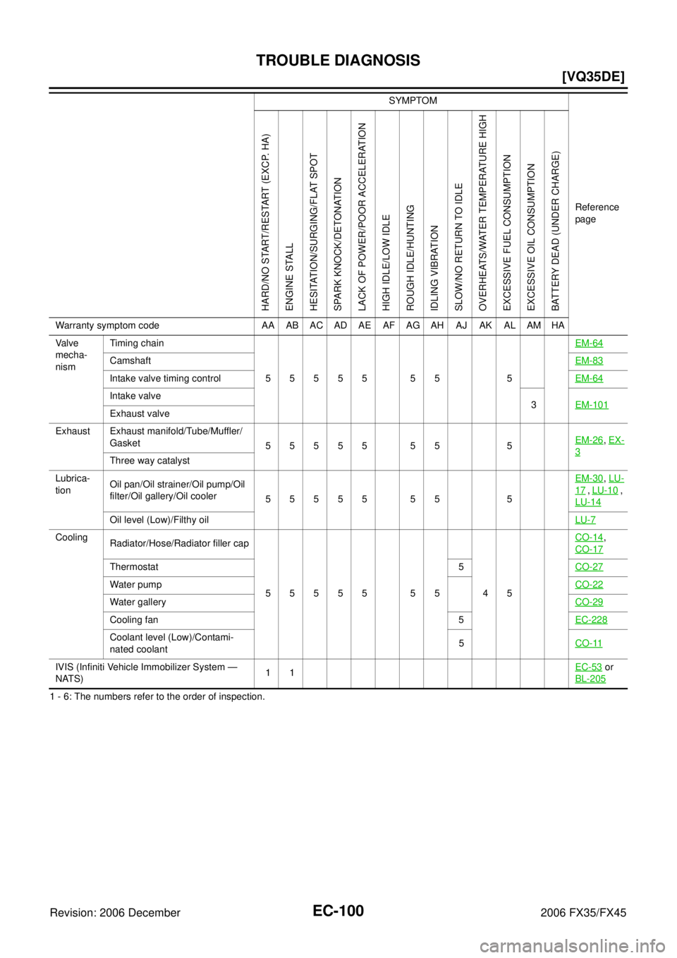
1 - 6: The numbers refer to the order of inspection. Va l v e
mecha-
nism Timing chain
55555 55 5 EM-64
Camshaft
EM-83
Intake valve timing controlEM-64
Intake valve
3 EM-101
Exhaust valve
Exhaust Exhaust manifold/Tube/Muffler/ Gasket 55555 55 5 EM-26
,
EX-
3Three way catalyst
Lubrica-
tion Oil pan/Oil strainer/Oil pump/Oil
filter/Oil gallery/Oil cooler 55555 55 5 EM-30
,
LU-
17 , LU-10 ,
LU-14
Oil level (Low)/Filthy oil LU-7
Cooling
Radiator/Hose/Radiator filler cap
55555 55 45 CO-14,
CO-17
Thermostat 5 CO-27
Water pumpCO-22
Water galleryCO-29
Cooling fan 5EC-228
Coolant level (Low)/Contami-
nated coolant 5
CO-11
IVIS (Infiniti Vehicle Immobilizer System —
NATS) 11
EC-53 or
BL-205
SYMPTOM
Reference
page
HARD/NO START/RESTART (EXCP. HA)
ENGINE STALL
HESITATION/SURGING/FLAT SPOT
SPARK KNOCK/DETONATION
LACK OF POWER/POOR ACCELERATION
HIGH IDLE/LOW IDLE
ROUGH IDLE/HUNTING
IDLING VIBRATION
SLOW/NO RETURN TO IDLE
OVERHEATS/WATER TEMPERATURE HIGH
EXCESSIVE FUEL CONSUMPTION
EXCESSIVE OIL CONSUMPTION
BATTERY DEAD (UNDER CHARGE)
Warranty symptom code AA AB AC AD AE AF AG AH AJ AK AL AM HA
Page 1598 of 4462
EC-214
[VQ35DE]
DTC P0117, P0118 ECT SENSOR
Revision: 2006 December 2006 FX35/FX45
3. CHECK ECT SENSOR GROUND CIRCUIT FOR OPEN AND SHORT
1. Turn ignition switch OFF.
2. Disconnect ECM harness connector.
3. Check harness continuity between ECT sensor terminal 2 and ECM terminal 67. Refer to Wiring Diagram.
4. Also check harness for short to ground and short to power.
OK or NG
OK >> GO TO 4.
NG >> Repair open circuit or short to ground or short to power in harness or connectors.
4. CHECK ENGINE COOLANT TEMPERATURE SENSOR
Refer to EC-214, "
Component Inspection" .
OK or NG
OK >> GO TO 5.
NG >> Replace engine coolant temperature sensor.
5. CHECK INTERMITTENT INCIDENT
Refer to EC-148, "
TROUBLE DIAGNOSIS FOR INTERMITTENT INCIDENT" .
>> INSPECTION END
Component InspectionNBS003NW
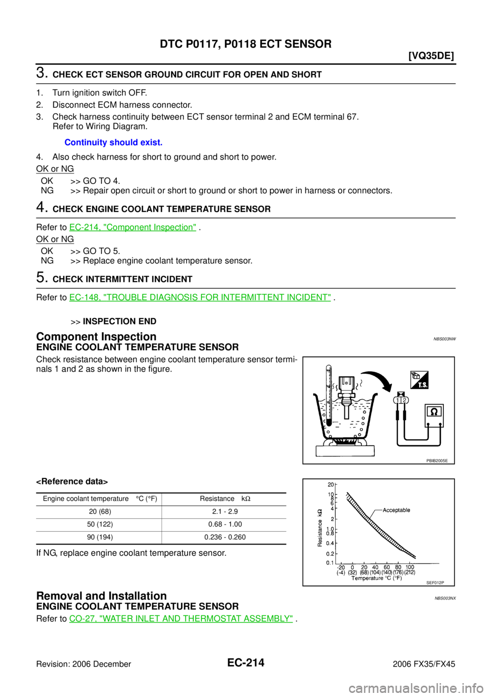
ENGINE COOLANT TEMPERATURE SENSOR
Check resistance between engine coolant temperature sensor termi-
nals 1 and 2 as shown in the figure.
If NG, replace engine coolant temperature sensor.
Removal and InstallationNBS003NX
ENGINE COOLANT TEMPERATURE SENSOR
Refer to CO-27, "WATER INLET AND THERMOSTAT ASSEMBLY" .
Continuity should exist.
PBIB2005E
Engine coolant temperature
°C ( °F) Resistance k Ω
20 (68) 2.1 - 2.9
50 (122) 0.68 - 1.00
90 (194) 0.236 - 0.260
SEF012P
Page 1608 of 4462
EC-224
[VQ35DE]
DTC P0125 ECT SENSOR
Revision: 2006 December 2006 FX35/FX45
3. CHECK THERMOSTAT OPERATION
When the engine is cold [lower than 70 °C (158 °F)] condition, grasp lower radiator hose and confirm the engine
coolant does not flow.
OK or NG
OK >> GO TO 4.
NG >> Repair or replace thermostat. Refer to CO-27, "
WATER INLET AND THERMOSTAT ASSEMBLY"
.
4. CHECK INTERMITTENT INCIDENT
Refer to EC-148, "
TROUBLE DIAGNOSIS FOR INTERMITTENT INCIDENT" .
Refer to EC-212, "
Wiring Diagram" .
>> INSPECTION END
Component InspectionNBS003OA
ENGINE COOLANT TEMPERATURE SENSOR
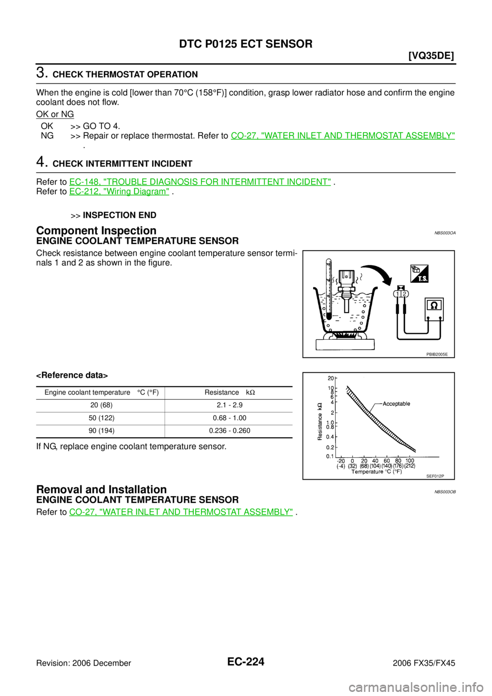
Check resistance between engine coolant temperature sensor termi-
nals 1 and 2 as shown in the figure.
If NG, replace engine coolant temperature sensor.
Removal and InstallationNBS003OB
ENGINE COOLANT TEMPERATURE SENSOR
Refer to CO-27, "WATER INLET AND THERMOSTAT ASSEMBLY" .
PBIB2005E
Engine coolant temperature °C ( °F) Resistance k Ω
20 (68) 2.1 - 2.9
50 (122) 0.68 - 1.00
90 (194) 0.236 - 0.260
SEF012P
Page 1612 of 4462
EC-228
[VQ35DE]
DTC P0128 THERMOSTAT FUNCTION
Revision: 2006 December 2006 FX35/FX45
DTC P0128 THERMOSTAT FUNCTIONPFP:21200
On Board Diagnosis LogicNBS003OI
Engine coolant temperature has not risen enough to open the thermostat even though the engine has run long
enough.
This is due to a leak in the seal or the thermostat stuck open.
DTC Confirmation ProcedureNBS003OJ
NOTE:
If DTC Confirmation Procedure has been previously conducted, always turn ignition switch OFF and wait at
least 10 seconds before conducting the next test.
TESTING CONDITION:
�For best results, perform at ambient temperature of –10 °C (14 °F) or higher.
�For best results, perform at engine coolant temperature of –10 °C (14 °F) to 60 °C (140 °F).
WITH CONSULT-II
1. Replace thermostat with new one. Refer to CO-27, "WATER INLET AND THERMOSTAT ASSEMBLY" .
Use only a genuine NISSAN thermostat as a replacement. If an incorrect thermostat is used, the MIL may
come on.
2. Turn ignition switch ON.
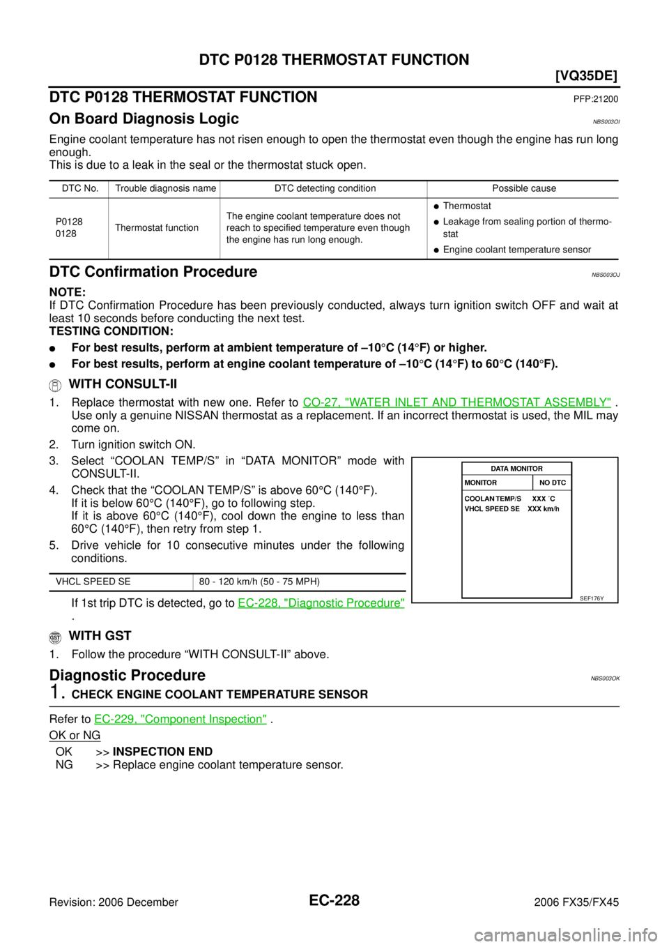
3. Select “COOLAN TEMP/S” in “DATA MONITOR” mode with CONSULT-II.
4. Check that the “COOLAN TEMP/S” is above 60 °C (140 °F).
If it is below 60 °C (140 °F), go to following step.
If it is above 60 °C (140 °F), cool down the engine to less than
60 °C (140 °F), then retry from step 1.
5. Drive vehicle for 10 consecutive minutes under the following conditions.
If 1st trip DTC is detected, go to EC-228, "
Diagnostic Procedure"
.
WITH GST
1. Follow the procedure “WITH CONSULT-II” above.
Diagnostic ProcedureNBS003OK
1. CHECK ENGINE COOLANT TEMPERATURE SENSOR
Refer to EC-229, "
Component Inspection" .
OK or NG
OK >> INSPECTION END
NG >> Replace engine coolant temperature sensor.
DTC No. Trouble diagnosis name DTC detecting condition Possible cause
P0128
0128 Thermostat function The engine coolant temperature does not
reach to specified temperature even though
the engine has run long enough.
�Thermostat
�Leakage from sealing portion of thermo-
stat
�Engine coolant temperature sensor
VHCL SPEED SE 80 - 120 km/h (50 - 75 MPH)
SEF176Y
Page 1613 of 4462
DTC P0128 THERMOSTAT FUNCTION EC-229
[VQ35DE]
C
D E
F
G H
I
J
K L
M A
EC
Revision: 2006 December 2006 FX35/FX45
Component InspectionNBS003OL
ENGINE COOLANT TEMPERATURE SENSOR
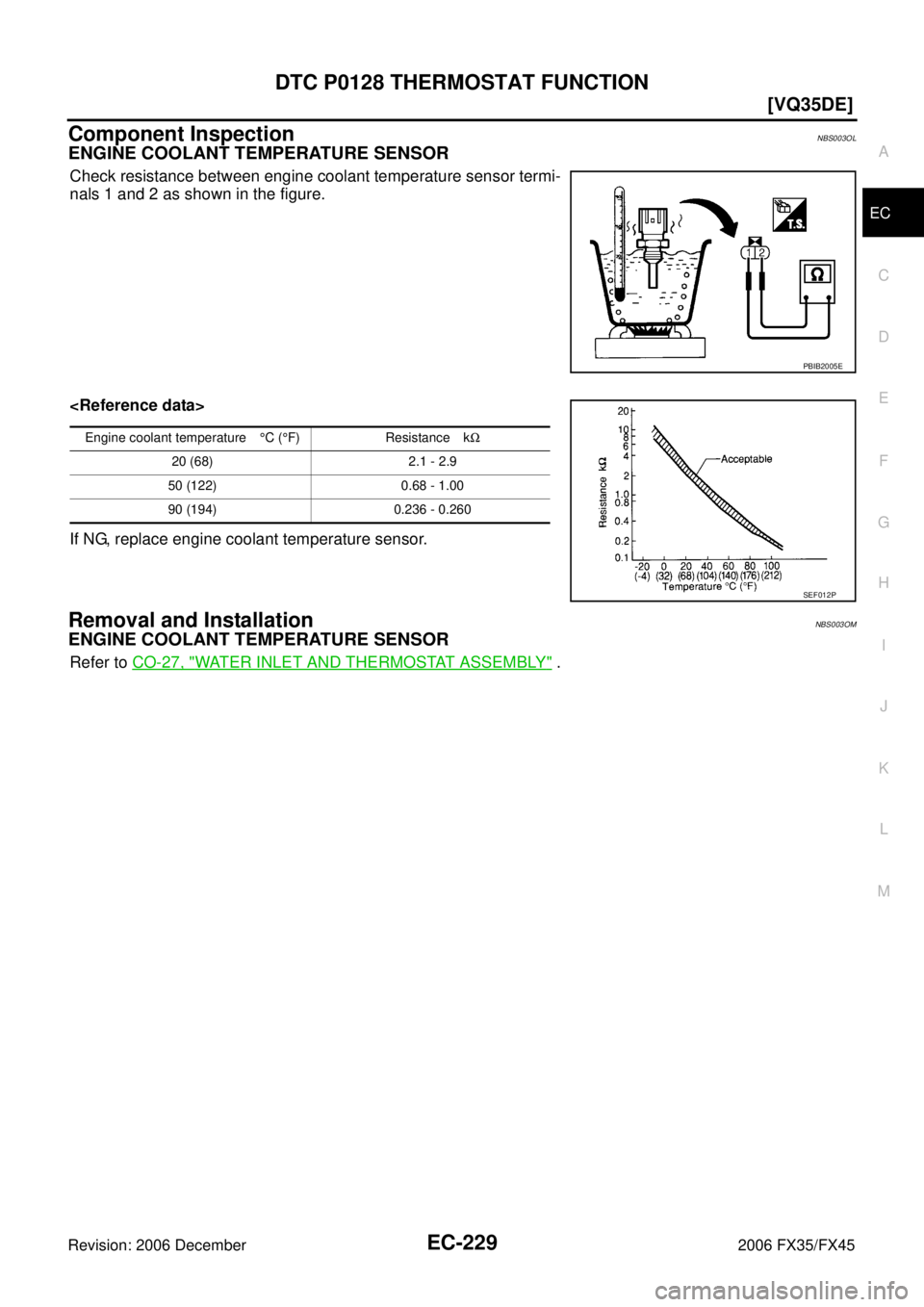
Check resistance between engine coolant temperature sensor termi-
nals 1 and 2 as shown in the figure.
If NG, replace engine coolant temperature sensor.
Removal and InstallationNBS003OM
ENGINE COOLANT TEMPERATURE SENSOR
Refer to CO-27, "WATER INLET AND THERMOSTAT ASSEMBLY" .
PBIB2005E
Engine coolant temperature °C ( °F) Resistance k Ω
20 (68) 2.1 - 2.9
50 (122) 0.68 - 1.00
90 (194) 0.236 - 0.260
SEF012P
Page 1672 of 4462
EC-288
[VQ35DE]
DTC P0138, P0158 HO2S2
Revision: 2006 December 2006 FX35/FX45
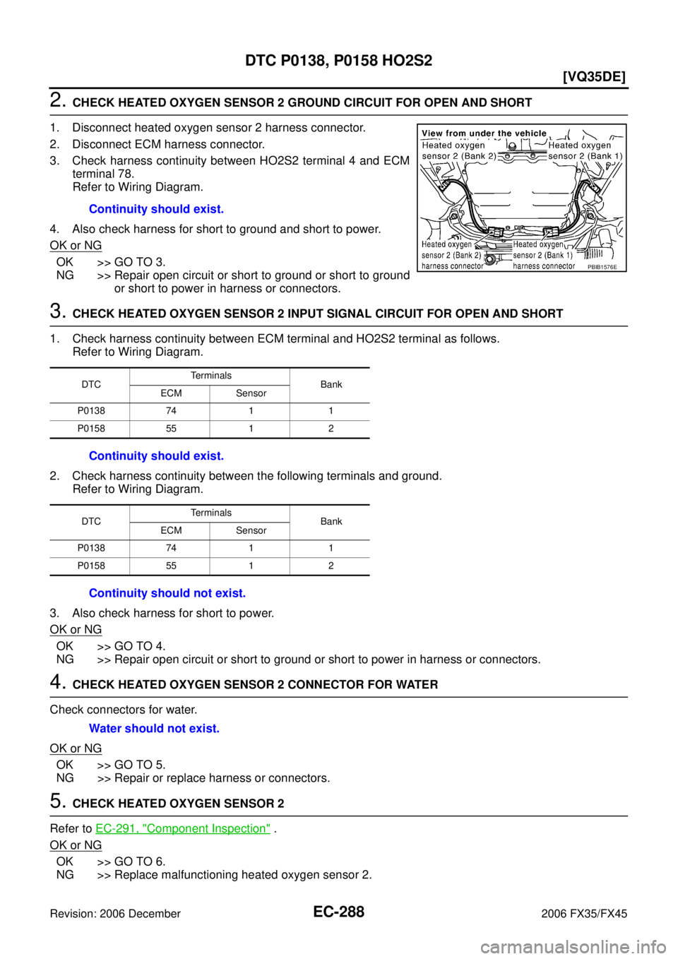
2. CHECK HEATED OXYGEN SENSOR 2 GROUND CIRCUIT FOR OPEN AND SHORT
1. Disconnect heated oxygen sensor 2 harness connector.
2. Disconnect ECM harness connector.
3. Check harness continuity between HO2S2 terminal 4 and ECM terminal 78.
Refer to Wiring Diagram.
4. Also check harness for short to ground and short to power.
OK or NG
OK >> GO TO 3.
NG >> Repair open circuit or short to ground or short to ground or short to power in harness or connectors.
3. CHECK HEATED OXYGEN SENSOR 2 INPUT SIGNAL CIRCUIT FOR OPEN AND SHORT
1. Check harness continuity between ECM terminal and HO2S2 terminal as follows. Refer to Wiring Diagram.
2. Check harness continuity between the following terminals and ground. Refer to Wiring Diagram.
3. Also check harness for short to power.
OK or NG
OK >> GO TO 4.
NG >> Repair open circuit or short to ground or short to power in harness or connectors.
4. CHECK HEATED OXYGEN SENSOR 2 CONNECTOR FOR WATER
Check connectors for water.
OK or NG
OK >> GO TO 5.
NG >> Repair or replace harness or connectors.
5. CHECK HEATED OXYGEN SENSOR 2
Refer to EC-291, "
Component Inspection" .
OK or NG
OK >> GO TO 6.
NG >> Replace malfunctioning heated oxygen sensor 2. Continuity should exist.
PBIB1576E
DTC
Terminals
Bank
ECM Sensor
P0138 74 1 1
P0158 55 1 2
Continuity should exist.
DTC Terminals
Bank
ECM Sensor
P0138 74 1 1
P0158 55 1 2
Continuity should not exist.
Water should not exist.