Page 3989 of 4462
HYDRAULIC LINE PS-41
C
D E
F
H I
J
K L
M A
B
PS
Revision: 2006 December 2006 FX35/FX45
Removal and InstallationNGS000CB
�Refer to PS-39, "Components" for tightening torque. Install in the reverse order of removal.
NOTE:
Refer to component parts location and do not reuse non-reusable parts.
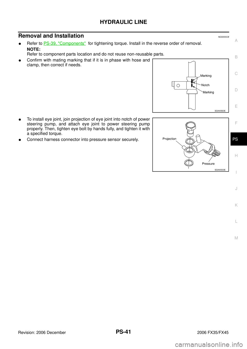
�Confirm with mating marking that if it is in phase with hose and
clamp, then correct if needs.
�To install eye joint, join projection of eye joint into notch of power
steering pump, and attach eye joint to power steering pump
properly. Then, tighten eye bolt by hands fully, and tighten it with
a specified torque.
�Connect harness connector into pressure sensor securely.
SGIA0563E
SGIA0533E
Page 3990 of 4462
PS-42
HYDRAULIC LINE
Revision: 2006 December 2006 FX35/FX45
ComponentNGS000CC
VK45DE AWD MODEL
SGIA0727E
1. Reservoir tank 2. Suction hose 3. High pressure hose
4. Oil cooler 5. Steering gear assembly 6. Reservoir tank bracket
7. Eye bolt
Page 3993 of 4462
SERVICE DATA AND SPECIFICATIONS (SDS) PS-45
C
D E
F
H I
J
K L
M A
B
PS
Revision: 2006 December 2006 FX35/FX45
Steering GearNGS000CI
Oil PumpNGS000CJ
Steering FluidNGS000CK
Tie-rod length “L” 135.2 mm (5.32 in)
SGIA0167E
Steering gear model PR26AM
Rack neutral position, dimension “L” (rack stroke) 67.0 mm (2.64 in)
Rack sliding force At the neutral point:
Range within ± 11.5 mm
( ± 0.453 in) from the neutral
position
(in power ON) Area average value 147
− 211 N (15 − 21.5 kg, 33 − 47 lb)
Allowable variation 98 N (10 kg, 22 lb) or less
Whole area (in power OFF) Peak value 294 N (30 kg, 66 lb) or less
Allowable variation 147 N (15 kg, 33 lb) or less
SGIA0629J
Oil pump relief hydraulic pressure 9,900 − 10,700 kPa (101 − 109.1 kg/cm2 , 1436 − 1552 psi)
Fluid capacity
Approx. 1.0 (1-1/8 US qt, 7/8 Imp qt)
Page 4022 of 4462
 by the signals")
RF-12
SUNROOF
Revision: 2006 December 2006 FX35/FX45
ANTI-PINCH FUNCTION
The CPU of sunroof motor monitors the sunroof motor operation and the sunroof position (fully-closed or
other) by the signals from sunroof motor.
When sunroof motor detects an interruption during the following slide close and tilt down operation, sunroof
switch controls the motor for open and the sunroof will operate until full up position (when tilt down operate) or
125 mm (4.92 in) or more in an open direction (when slide close operate).
�close operation and tilt down when ignition switch is in the ON position.
�close operation and tilt down during retained power operation.
MEMORY RESET PROCEDURE
1. Please observe the following instructions while confirming the sunroof operation.
NOTE:
Do not disconnect the electronic power while the sunroof is operating or within 5 seconds after the sunroof
stops. (to wipe-out the memory of lid position and operating friction.)
2. Initialization of system should be conducted after the following conditions.
�When the battery is out or connector is disconnected while sunroof is operating or within 5 seconds
after sunroof stops.
�When the sunroof motor is changed.
�When an emergency handle is used.
�When the sunroof does not operate normally. (Incomplete initialization conditions)
INITIALIZATION PROCEDURE
If the sunroof does not close or open automatically, use the following procedure to return sunroof operation to
normal.
1. Close the sunroof if it is not in the closed position. It may be necessary to repeatedly push the switch to close the sunroof.
2. Press and hold the TILT UP switch. Do not release the switch, keep pressure on it. After 10 seconds of depressing, the sunroof will tilt up, then tilt down. Release the button.
3. Press and hold the TILT UP switch again. Do not release the switch, keep pressure on it. While depress- ing the switch, the sunroof will “Slide open” “Slide close” “Tilt up” “Tilt down”. Release the button after the
sunroof “Tilts down” and stops.
4. Initializing procedure is complete. Confirm proper operation of the sunroof (slide open, slide close, tilt up, tilt down.)
CAN Communication System DescriptionNIS001SZ
CAN (Controller Area Network) is a serial communication line for real time application. It is an on-vehicle mul-
tiplex communication line with high data communication speed and excellent error detection ability. Many elec-
tronic control units are equipped onto a vehicle, and each control unit shares information and links with other
control units during operation (not independent). In CAN communication, control units are connected with 2
communication lines (CAN H line, CAN L line) allowing a high rate of information transmission with less wiring.
Each control unit transmits/receives data but selectively reads required data only.
CAN Communication UnitNIS001T0
Refer to LAN-27, "CAN COMMUNICATION" .
Page 4081 of 4462

REAR SUSPENSION ASSEMBLY RSU-5
C
D
F
G H
I
J
K L
M A
B
RSU
Revision: 2006 December 2006 FX35/FX45
REAR SUSPENSION ASSEMBLYPFP:55020
On-Vehicle Inspection and ServiceNES000HU
Make sure the mounting conditions (looseness, back lash) of each component and component status (wear,
damage) are normal.
INSPECTION OF BALL JOINT END PLAY
Measure axial end play by installing and moving up/down with an
iron pry bar or something similar between suspension arm and axle.
CAUTION:
Be careful not to damage ball joint boot.
SHOCK ABSORBER INSPECTION
Check shock absorber for oil leakage, damage and replace if necessary.
Wheel Alignment InspectionNES000HV
DESCRIPTION
�Measure wheel alignment under unladen conditions. “Unladen conditions” means that fuel, engine cool-
ant, and lubricant are full. Spare tire, jack, hand tools and mats in designated positions.
PRELIMINARY INSPECTION
�Check tires for improper air pressure and wear.
�Check road wheels for runout.
�Check wheel bearing axial end play.
�Check ball joint axial end play of suspension arm.
�Check shock absorber operation.
�Check each mounting point of axle and suspension for looseness and deformation.
�Check each link, arm and member for cracks, deformation, and other damage.
�Check vehicle posture.
GENERAL INFORMATION AND RECOMMENDATIONS
�A four-wheel thrust alignment should be performed.
–This type of alignment is recommended for any NISSAN/INFINITI vehicle.
–The four-wheel “thrust” process helps ensure that the vehicle is properly aligned and the steering wheel is
centered.
–The alignment rack itself should be capable of accepting any NISSAN/INFINITI vehicle.
–The rack should be checked to ensure that it is level.
�Make sure the machine is properly calibrated.
–Your alignment equipment should be regularly calibrated in order to give correct information.
–Check with the manufacturer of your specific equipment for their recommended Service/Calibration
Schedule. Standard value
Axial end play : 0 mm (0 in)
SEIA0245J
Page 4118 of 4462

SC-12
STARTING SYSTEM
Revision: 2006 December 2006 FX35/FX45
DIAGNOSTIC PROCEDURE 1
Check “B” Terminal Circuit
1. CHECK POWER SUPPLY FOR STARTER MOTOR “B” TERMINAL
1. Remove fuel pump fuse.
2. Crank or start the engine (where possible) until the fuel pressure is released.
3. Turn ignition switch OFF.
4. Make sure that the starter motor “B” terminal E313 terminal 2 connection is clean and tight.
5. Check voltage between starter motor “B” terminal E313 terminal 2 and ground.
OK or NG
OK >> GO TO 2.
NG >> Check harness between battery and starter motor for open circuit.
2. CHECK BATTERY CABLE CONNECTION (VOLTAGE DROP TEST)
Check voltage between starter motor “B” terminal E313 terminal 2
and battery positive terminal.
OK or NG
OK >> GO TO 3.
NG >> Check harness between battery and starter motor for poor continuity.
3. CHECK STARTER MOTOR GROUND CIRCUIT (VOLTAGE DROP TEST)
1. Turn ignition switch OFF.
2. Check voltage between starter motor case and battery negative terminal.
OK or NG
OK >> “B” terminal circuit is OK. Further inspection necessary. Refer to SC-11, "
Trouble Diagnosis with Starting/Charg-
ing System Tester (Starting)" .
NG >> Check starter motor case and ground for poor continuity.
*1 For battery testing, use Battery Ser-
vice Center (J-48087). For details
and operating instructions, refer to
Technical Service Bulletin and/or
Battery Service Center User Guide. *2
SC-13, "MINIMUM SPECIFICATION
OF CRANKING VOLTAGE REFER-
ENCING COOLANT TEMPERA-
TURE"
*3SC-12, "Check “B” Terminal Circuit"
*4SC-13, "Check “S” Connector Cir-
cuit"
2 – Ground : Battery voltage
PKIB8793E
2 – Battery positive terminal
When ignition switch is in START
position : Less than 0.5 V
PKIB8794E
Starter motor case – Battery negative terminal
When ignition switch is in
START position : Less than 0.2 V
PKIB8795E
Page 4119 of 4462

STARTING SYSTEM SC-13
C
D E
F
G H
I
J
L
M A
B
SC
Revision: 2006 December 2006 FX35/FX45
DIAGNOSTIC PROCEDURE 2
Check “S” Connector Circuit
1. CHECK POWER SUPPLY FOR STARTER MOTOR “S” TERMINAL
1. Remove fuel pump fuse.
2. Crank or start the engine (where possible) until the fuel pressure is released.
3. Turn ignition switch OFF.
4. Disconnect starter motor connector.
5. Check voltage between starter motor harness connector E312 (VK45DE) or F33 (VQ35DE) terminal 1 and ground.
OK or NG
OK >> “S” connector circuit is OK. Further inspection neces- sary. Refer to SC-11, "
Trouble Diagnosis with Starting/
Charging System Tester (Starting)" .
NG >> Check the following.
�40A fusible link (letter F , located in fuse and fusible link box)
�Ignition switch
�Starter relay (within the IPDM E/R)
�Harness for open or short
MINIMUM SPECIFICATION OF CRANKING VOLTAGE REFERENCING COOLANT TEMPERA-
TURE
1 – Ground
When ignition switch is in
START position : Battery voltage
PKIB8796E
Engine coolant temperature Voltage [V]
− 30 °C to −20 °C ( −22 °F to −4°F) 8.4
− 19 °C to −10 °C ( −2°F to 14 °F) 8.9
− 9°C to 0 °C (16 °F to 32 °F) 9.3
More than 1 °C (More than 34 °F) 9.7
Page 4135 of 4462
CHARGING SYSTEM SC-29
C
D E
F
G H
I
J
L
M A
B
SC
Revision: 2006 December 2006 FX35/FX45
7. Remove oil pressure switch harness clip from alternator stay. (2WD)
8. Disconnect oil pressure switch connector. (2WD)
9. Remove alternator stay mounting bolts and alternator stay, using power tools.
10. Remove alternator mounting bolt, using power tools.
11. Remove alternator assembly downward from the vehicle.
Alternator Pulley Inspection
Perform the following.
�Make sure that alternator pulley does not rattle.
�Make sure that alternator pulley nut is tight.
Installation
Installation is the reverse order of removal.
�Install alternator, and check tension of belt. Refer to EM-15, "Checking Drive Belts" .
CAUTION:
Be sure to tighten “B” terminal nut carefully.
PKIA1923E
Alternator pulley nut:
: 118 N·m (12.0 kg-m, 87 ft-lb)

 PS-45
C
D E
F
H I
J
K L
M A
B
PS
Revision: 2006 December 2006 FX35/FX45
Steering GearNGS000CI
Oil PumpNGS000CJ
Steering FluidNGS000CK
Tie-rod length �")

8. Disconnect oil pressure")