Page 2694 of 4462
EC-1310
[VK45DE]
FUEL INJECTOR
Revision: 2006 December 2006 FX35/FX45
3. CHECK FUNCTION OF FUEL INJECTOR-I
1. Turn ignition switch OFF.
2. Disconnect harness connector F21, F201 (bank 1) and F41, F221 (bank 2).
3. Turn ignition switch ON.
4. Check voltage between the following; harness connector F21 terminal 5 and ground,
harness connector F41 terminal 5 and ground
with CONSULT-II or tester.
5. Turn ignition switch OFF.
6. Disconnect ECM harness connector.
7. Check harness continuity between the following terminals.
8. Also check harness for short to ground and short to power.
OK or NG
OK >> GO TO 5.
NG >> GO TO 4.
: Vehicle front 1. Harness connectors F41, F221 2. Harness connectors F21, F201
Voltage: Battery voltage
Cylinder Harness connector terminal ECM terminal
1 F21 terminal 3 23
3 F21 terminal 2 22
5 F21 terminal 1 21
7 F21 terminal 6 44
2 F41 terminal 3 42
4 F41 terminal 2 41
6 F41 terminal 1 40
8 F41 terminal 6 63
Continuity should exist.
PBIB3248E
PBIB0180E
Page 2695 of 4462
FUEL INJECTOR EC-1311
[VK45DE]
C
D E
F
G H
I
J
K L
M A
EC
Revision: 2006 December 2006 FX35/FX45
4. DETECT MALFUNCTIONING PART
Check the following.
�Harness connectors M82, F102
�Harness connectors F21, F201
�Harness connectors F41, F221
�Fuse block (J/B) connector M1
�15A fuse
�Harness for open or short between harness connector F21 and fuse
�Harness for open or short between harness connector F41 and fuse
�Harness for open or short between harness connector F21 and ECM
�Harness for open or short between harness connector F41 and ECM
>> Repair open circuit or short to ground or short to power in harness or connectors.
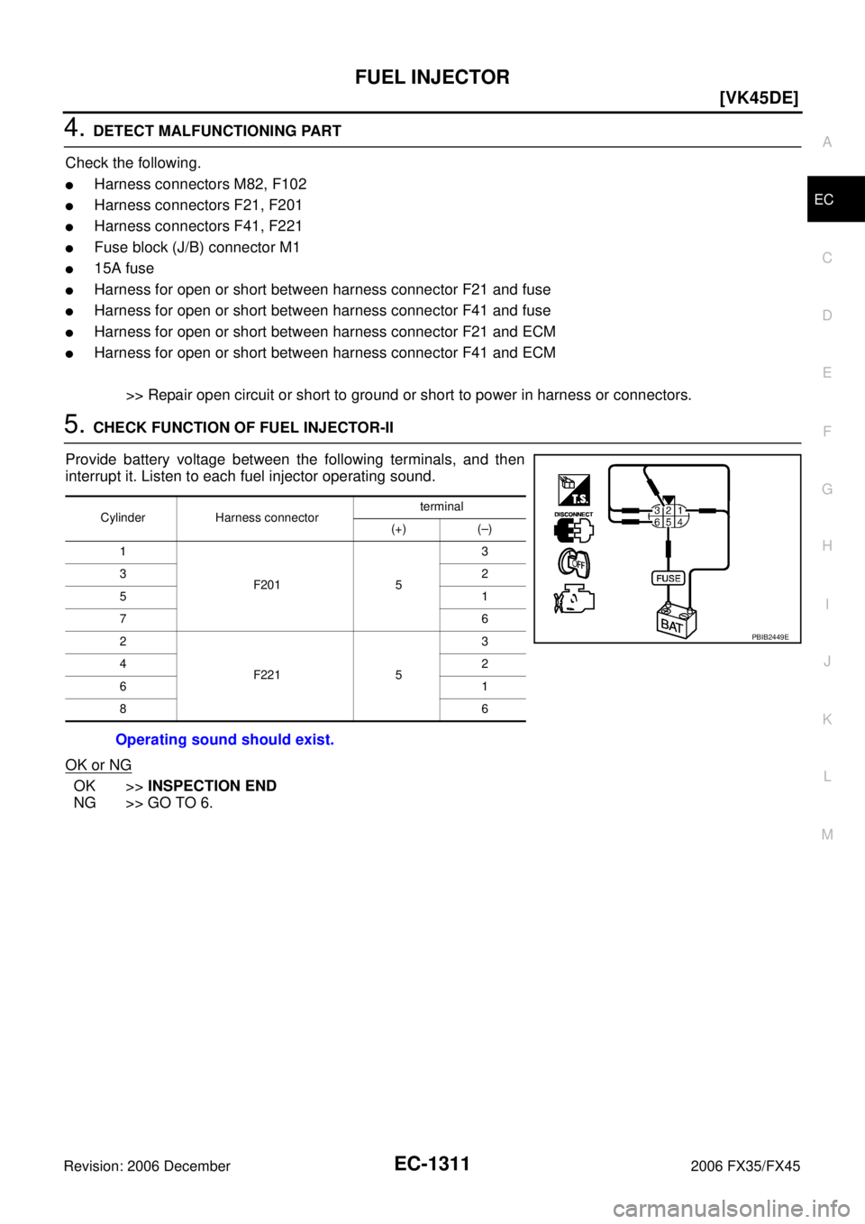
5. CHECK FUNCTION OF FUEL INJECTOR-II
Provide battery voltage between the following terminals, and then
interrupt it. Listen to each fuel injector operating sound.
OK or NG
OK >> INSPECTION END
NG >> GO TO 6.
Cylinder Harness connector terminal
(+) (–)
1
F201 5 3
32
51
76
2
F221 5 3
42
61
86
Operating sound should exist.
PBIB2449E
Page 2696 of 4462
EC-1312
[VK45DE]
FUEL INJECTOR
Revision: 2006 December 2006 FX35/FX45
6. CHECK SUB-HARNESS CIRCUIT FOR OPEN AND SHORT
1. Disconnect fuel injector harness connectors.
2. Check harness continuity between the following terminals. Refer to Wiring Diagram.
3. Also check harness for short to ground and short to power.
OK or NG
OK >> GO TO 7.
NG >> Repair open circuit or short to ground or short to power in harness or connectors.
7. CHECK FUEL INJECTOR
Refer to EC-1313, "
Component Inspection" .
OK or NG
OK >> GO TO 8.
NG >> Replace fuel injector.
8. CHECK INTERMITTENT INCIDENT
Refer to EC-811, "
TROUBLE DIAGNOSIS FOR INTERMITTENT INCIDENT" .
>> INSPECTION END
: Vehicle front 1. Fuel injector (bank 2) 2. Fuel injector (bank 1)
Harness connector terminal Fuel injector terminal F201 terminal 1
2
F201 terminal 2
F201 terminal 3
F201 terminal 6
F201 terminal 5 1
F221 terminal 1
2
F221 terminal 2
F221 terminal 3
F221 terminal 6
F221 terminal 5 1
Continuity should exist.
PBIB3235E
Page 2697 of 4462
FUEL INJECTOR EC-1313
[VK45DE]
C
D E
F
G H
I
J
K L
M A
EC
Revision: 2006 December 2006 FX35/FX45
Component InspectionNBS004H2
FUEL INJECTOR
1. Disconnect fuel injector harness connector.
2. Check resistance between terminals as shown in the figure.
Removal and InstallationNBS004H3
FUEL INJECTOR
Refer to EM-194, "FUEL INJECTOR AND FUEL TUBE" .
Resistance: 13.5 - 17.5
Ω [at 10 - 60 °C (50 - 140 °F)]
PBIB1727E
Page 2698 of 4462
![INFINITI FX35 2006 Service Manual EC-1314
[VK45DE]
FUEL PUMP
Revision: 2006 December 2006 FX35/FX45
FUEL PUMPPFP:17042
DescriptionNBS004H4
SYSTEM DESCRIPTION
*: ECM determines the start signal status by the signals of engine speed and](/manual-img/42/57019/w960_57019-2697.png "INFINITI FX35 2006 Service Manual EC-1314
[VK45DE]
FUEL PUMP
Revision: 2006 December 2006 FX35/FX45
FUEL PUMPPFP:17042
DescriptionNBS004H4
SYSTEM DESCRIPTION
*: ECM determines the start signal status by the signals of engine speed and")
EC-1314
[VK45DE]
FUEL PUMP
Revision: 2006 December 2006 FX35/FX45
FUEL PUMPPFP:17042
DescriptionNBS004H4
SYSTEM DESCRIPTION
*: ECM determines the start signal status by the signals of engine speed and battery voltage.
The ECM activates the fuel pump for several seconds after the ignition switch is turned ON to improve engine
startability. If the ECM receives a engine speed signal from the camshaft position sensor (PHASE), it knows
that the engine is rotating, and causes the pump to operate. If the engine speed signal is not received when
the ignition switch is ON, the engine stalls. The ECM stops pump operation and prevents battery discharging,
thereby improving safety. The ECM does not directly drive the fuel pump. It controls the ON/OFF fuel pump
relay, which in turn controls the fuel pump.
COMPONENT DESCRIPTION
A turbine type design fuel pump is used in the fuel tank.
CONSULT-II Reference Value in Data Monitor ModeNBS004H5
Specification data are reference values.
Sensor Input signal to ECM ECM Function Actuator
Crankshaft position sensor (POS)
Camshaft position sensor (PHASE) Engine speed*
Fuel pump control Fuel pump relay
Battery Battery voltage*
Condition Fuel pump operation
Ignition switch is turned to ON. Operates for 1 second.
Engine running and cranking Operates.
When engine is stopped Stops in 1.5 seconds.
Except as shown above Sto ps.
PBIB1508E
MONITOR ITEM CONDITION SPECIFICATION
FUEL PUMP RLY
�For 1 seconds after turning ignition switch: ON
�Engine running or cranking ON
�Except above OFF
Page 2699 of 4462
FUEL PUMP EC-1315
[VK45DE]
C
D E
F
G H
I
J
K L
M A
EC
Revision: 2006 December 2006 FX35/FX45
Wiring DiagramNBS004H6
TBWM1363E
Page 2700 of 4462
![INFINITI FX35 2006 Service Manual EC-1316
[VK45DE]
FUEL PUMP
Revision: 2006 December 2006 FX35/FX45
Specification data are reference values and are measured between each terminal and ground.
CAUTION:
Do not use ECM ground terminals](/manual-img/42/57019/w960_57019-2699.png "INFINITI FX35 2006 Service Manual EC-1316
[VK45DE]
FUEL PUMP
Revision: 2006 December 2006 FX35/FX45
Specification data are reference values and are measured between each terminal and ground.
CAUTION:
Do not use ECM ground terminals")
EC-1316
[VK45DE]
FUEL PUMP
Revision: 2006 December 2006 FX35/FX45
Specification data are reference values and are measured between each terminal and ground.
CAUTION:
Do not use ECM ground terminals when measuring input/output voltage. Doing so may result in dam-
age to the ECM's transistor. Use a ground other than ECM terminals, such as the ground.
Diagnostic ProcedureNBS004H7
1. CHECK OVERALL FUNCTION
1. Turn ignition switch ON.
2. Pinch fuel feed hose (1) with two fingers. Fuel pressure pulsation should be felt on the fuel feed hose
for 1 second after ignition switch is turned ON.
OK or NG
OK >> INSPECTION END
NG >> GO TO 2.
2. CHECK FUEL PUMP POWER SUPPLY CIRCUIT-I
1. Turn ignition switch OFF.
2. Disconnect ECM harness connector.
3. Turn ignition switch ON.
4. Check voltage between ECM terminal 113 and ground with CONSULT-II or tester.
OK or NG
OK >> GO TO 5.
NG >> GO TO 3.
TER-
MINAL NO. WIRE
COLOR ITEM CONDITION DATA (DC Voltage)
11 3 G Y / R F u e l p u m p r e l a y [Ignition switch: ON]
�For 1 second after turning ignition switch ON
[Engine is running] 0 - 1.5V
[Ignition switch: ON]
�More than 1 second after turning ignition
switch ON BATTERY VOLTAGE
(11 - 14V)
PBIB3245E
Voltage: Battery voltage
PBIB1187E
Page 2701 of 4462
![INFINITI FX35 2006 Service Manual FUEL PUMP EC-1317
[VK45DE]
C
D E
F
G H
I
J
K L
M A
EC
Revision: 2006 December 2006 FX35/FX45
3. CHECK FUEL PUMP POWER SUPPLY CIRCUIT-II
1. Turn ignition switch OFF.
2. Disconnect IPDM E/](/manual-img/42/57019/w960_57019-2700.png "INFINITI FX35 2006 Service Manual FUEL PUMP EC-1317
[VK45DE]
C
D E
F
G H
I
J
K L
M A
EC
Revision: 2006 December 2006 FX35/FX45
3. CHECK FUEL PUMP POWER SUPPLY CIRCUIT-II
1. Turn ignition switch OFF.
2. Disconnect IPDM E/")
FUEL PUMP EC-1317
[VK45DE]
C
D E
F
G H
I
J
K L
M A
EC
Revision: 2006 December 2006 FX35/FX45
3. CHECK FUEL PUMP POWER SUPPLY CIRCUIT-II
1. Turn ignition switch OFF.
2. Disconnect IPDM E/R harness connector E8.
3. Turn ignition switch ON.
4. Check voltage between IPDM E/R terminal 40 and ground with CONSULT-II or tester.
OK or NG
OK >> GO TO 4.
NG >> GO TO 11.
4. DETECT MALFUNCTIONING PART
Check the following.
�Harness connectors E211, M41
�Harness for open or short between IPDM E/R and ECM
>> Repair open circuit or short to ground or short to power in harness or connectors.
5. CHECK FUEL PUMP POWER SUPPLY CIRCUIT-III
1. Turn ignition switch OFF.
2. Reconnect all harness connectors disconnected.
3. Disconnect “fuel level sensor unit and fuel pump” harness con- nector.
4. Turn ignition switch ON.
5. Check voltage between “fuel level sensor unit and fuel pump” terminal 1 and ground with CONSULT-II or tester.
OK or NG
OK >> GO TO 9.
NG >> GO TO 6. Voltage: Battery voltage
PBIB1926E
PBIB1507E
Voltage: Battery voltage should exist for 1 sec-
ond after ignition switch is turned ON.
PBIB0795E
![INFINITI FX35 2006 Service Manual EC-1310
[VK45DE]
FUEL INJECTOR
Revision: 2006 December 2006 FX35/FX45
3. CHECK FUNCTION OF FUEL INJECTOR-I
1. Turn ignition switch OFF.
2. Disconnect harness connector F21, F201 (bank 1) and F41, F2](/manual-img/42/57019/w960_57019-2693.png "INFINITI FX35 2006 Service Manual EC-1310
[VK45DE]
FUEL INJECTOR
Revision: 2006 December 2006 FX35/FX45
3. CHECK FUNCTION OF FUEL INJECTOR-I
1. Turn ignition switch OFF.
2. Disconnect harness connector F21, F201 (bank 1) and F41, F2")
![INFINITI FX35 2006 Service Manual EC-1312
[VK45DE]
FUEL INJECTOR
Revision: 2006 December 2006 FX35/FX45
6. CHECK SUB-HARNESS CIRCUIT FOR OPEN AND SHORT
1. Disconnect fuel injector harness connectors.
2. Check harness continuity betw](/manual-img/42/57019/w960_57019-2695.png "INFINITI FX35 2006 Service Manual EC-1312
[VK45DE]
FUEL INJECTOR
Revision: 2006 December 2006 FX35/FX45
6. CHECK SUB-HARNESS CIRCUIT FOR OPEN AND SHORT
1. Disconnect fuel injector harness connectors.
2. Check harness continuity betw")
![INFINITI FX35 2006 Service Manual FUEL INJECTOR EC-1313
[VK45DE]
C
D E
F
G H
I
J
K L
M A
EC
Revision: 2006 December 2006 FX35/FX45
Component InspectionNBS004H2
FUEL INJECTOR
1. Disconnect fuel injector harness connector.](/manual-img/42/57019/w960_57019-2696.png "INFINITI FX35 2006 Service Manual FUEL INJECTOR EC-1313
[VK45DE]
C
D E
F
G H
I
J
K L
M A
EC
Revision: 2006 December 2006 FX35/FX45
Component InspectionNBS004H2
FUEL INJECTOR
1. Disconnect fuel injector harness connector.")
![INFINITI FX35 2006 Service Manual FUEL PUMP EC-1315
[VK45DE]
C
D E
F
G H
I
J
K L
M A
EC
Revision: 2006 December 2006 FX35/FX45
Wiring DiagramNBS004H6
TBWM1363E](/manual-img/42/57019/w960_57019-2698.png "INFINITI FX35 2006 Service Manual FUEL PUMP EC-1315
[VK45DE]
C
D E
F
G H
I
J
K L
M A
EC
Revision: 2006 December 2006 FX35/FX45
Wiring DiagramNBS004H6
TBWM1363E")