Page 2824 of 4462
![INFINITI FX35 2006 Service Manual EM-30
[VQ35DE]
OIL PAN AND OIL STRAINER
Revision: 2006 December 2006 FX35/FX45
OIL PAN AND OIL STRAINERP F P : 1111 0
Components (2WD Models)NBS003GB
Removal and Installation (2WD Models)NBS003GC
REMO](/manual-img/42/57019/w960_57019-2823.png "INFINITI FX35 2006 Service Manual EM-30
[VQ35DE]
OIL PAN AND OIL STRAINER
Revision: 2006 December 2006 FX35/FX45
OIL PAN AND OIL STRAINERP F P : 1111 0
Components (2WD Models)NBS003GB
Removal and Installation (2WD Models)NBS003GC
REMO")
EM-30
[VQ35DE]
OIL PAN AND OIL STRAINER
Revision: 2006 December 2006 FX35/FX45
OIL PAN AND OIL STRAINERP F P : 1111 0
Components (2WD Models)NBS003GB
Removal and Installation (2WD Models)NBS003GC
REMOVAL
CAUTION:
To avoid the danger of being scalded, never drain engine oil when the engine is hot.
NOTE:
To remove oil pan (lower) only, take step 5, then step 20. Removal of step 1, hood assembly (step 2) and step
4 are unnecessary.
1. Remove front tire.
2. Remove hood assembly. Refer to BL-13, "
HOOD" .
3. Remove front and rear engine undercover with power tool.
4. Remove front cross bar with power tool. FSU-6, "
FRONT SUSPENSION ASSEMBLY" .
5. Drain engine oil. Refer to LU-9, "
Changing Engine Oil" .
CAUTION:
�Perform this step when the engine is cold.
1. Oil pan gasket (rear) 2. Oil pan (upper) 3. O-ring
4. Oil pan gasket (front) 5. Oil filter 6. Connector bolt
7. Oil cooler 8. O-ring 9. Relief valve
10. Oil pressure switch 11. Bracket 12. Oil strainer
13. Drain plug 14. Drain plug washer 15. Oil pan (lower)
16. Rear plate 17. Crankshaft position sensor (POS) 18. Seal rubber
19. Rear cover plate
SBIA0587E
Page 2838 of 4462
EM-44
[VQ35DE]
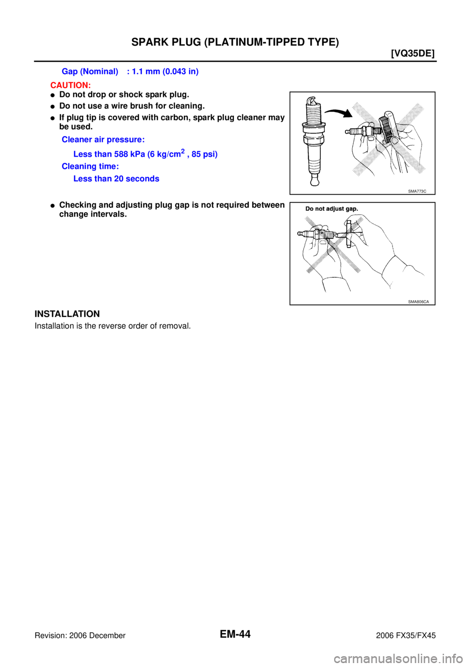
SPARK PLUG (PLATINUM-TIPPED TYPE)
Revision: 2006 December 2006 FX35/FX45
CAUTION:
�Do not drop or shock spark plug.
�Do not use a wire brush for cleaning.
�If plug tip is covered with carbon, spark plug cleaner may
be used.
�Checking and adjusting plug gap is not required between
change intervals.
INSTALLATION
Installation is the reverse order of removal. Gap (Nominal) : 1.1 mm (0.043 in)
Cleaner air pressure: Less than 588 kPa (6 kg/cm
2 , 85 psi)
Cleaning time: Less than 20 seconds
SMA773C
SMA806CA
Page 2839 of 4462
![INFINITI FX35 2006 Service Manual FUEL INJECTOR AND FUEL TUBE EM-45
[VQ35DE]
C
D E
F
G H
I
J
K L
M A
EM
Revision: 2006 December 2006 FX35/FX45
FUEL INJECTOR AND FUEL TUBEPFP:16600
ComponentsNBS003GJ
CAUTION:
Do not remove](/manual-img/42/57019/w960_57019-2838.png "INFINITI FX35 2006 Service Manual FUEL INJECTOR AND FUEL TUBE EM-45
[VQ35DE]
C
D E
F
G H
I
J
K L
M A
EM
Revision: 2006 December 2006 FX35/FX45
FUEL INJECTOR AND FUEL TUBEPFP:16600
ComponentsNBS003GJ
CAUTION:
Do not remove")
FUEL INJECTOR AND FUEL TUBE EM-45
[VQ35DE]
C
D E
F
G H
I
J
K L
M A
EM
Revision: 2006 December 2006 FX35/FX45
FUEL INJECTOR AND FUEL TUBEPFP:16600
ComponentsNBS003GJ
CAUTION:
Do not remove or disassemble parts unless instructed as shown in the figure.
Removal and InstallationNBS003GK
REMOVAL
WARNING:
�Put a “CAUTION FLAMMABLE” sign in the workshop.
�Be sure to work in a well ventilated area and furnish workshop with a CO2 fire extinguisher.
�Do not smoke while servicing fuel system. Keep open flames and sparks away from the work area.
�To avoid the danger of being scalded, do not drain engine coolant when the engine is hot.
1. Remove engine cover with power tool. Refer to EM-19, "
INTAKE MANIFOLD COLLECTOR" .
2. Release fuel pressure. Refer to EC-86, "
FUEL PRESSURE RELEASE" .
3. Drain engine coolant, or when water hoses are disconnected, attach plug to prevent engine coolant leak- age. Refer to CO-11, "
Changing Engine Coolant" and EM-19, "INTAKE MANIFOLD COLLECTOR" .
CAUTION:
Perform this step when the engine is cold.
1. Fuel damper 2. O-ring 3. Fuel sub-tube
4. EVAP hose 5. Intake manifold collector (lower) 6. Fuel feed hose (with damper)
7. Fuel tube 8. Spacer 9. Clip
10. O-ring (blue) 11. Fuel injector 12. O-ring (brown)
13. Hose clamp 14. Bracket 15. Quick connector cap
16. Centralized under-floor piping
SBIA0580E
Page 2844 of 4462
EM-50
[VQ35DE]
FUEL INJECTOR AND FUEL TUBE
Revision: 2006 December 2006 FX35/FX45
INSPECTION AFTER INSTALLATION
Check on Fuel Leakage
1. Turn ignition switch “ON” (with the engine stopped). With fuel pressure applied to fuel piping, make sure there are no fuel leaks at connection points.
NOTE:
Use mirrors for checking at points out of clear sight.
2. Start the engine. With engine speed increased, make sure again that there are no fuel leaks at connection points.
CAUTION:
Do not touch the engine immediately after stopped, as the engine becomes extremely hot.
Page 2845 of 4462
![INFINITI FX35 2006 Service Manual ROCKER COVER EM-51
[VQ35DE]
C
D E
F
G H
I
J
K L
M A
EM
Revision: 2006 December 2006 FX35/FX45
ROCKER COVERPFP:13264
ComponentsNBS003GL
Removal and InstallationNBS003GM
REMOVAL
1. Remove en](/manual-img/42/57019/w960_57019-2844.png "INFINITI FX35 2006 Service Manual ROCKER COVER EM-51
[VQ35DE]
C
D E
F
G H
I
J
K L
M A
EM
Revision: 2006 December 2006 FX35/FX45
ROCKER COVERPFP:13264
ComponentsNBS003GL
Removal and InstallationNBS003GM
REMOVAL
1. Remove en")
ROCKER COVER EM-51
[VQ35DE]
C
D E
F
G H
I
J
K L
M A
EM
Revision: 2006 December 2006 FX35/FX45
ROCKER COVERPFP:13264
ComponentsNBS003GL
Removal and InstallationNBS003GM
REMOVAL
1. Remove engine cover with power tool. Refer to EM-19, "INTAKE MANIFOLD COLLECTOR" .
2. Release the fuel pressure. Refer to EC-86, "
FUEL PRESSURE RELEASE" .
3. Drain engine coolant, or when water hoses are disconnected, attach plug to prevent engine coolant leak- age. Refer to CO-11, "
Changing Engine Coolant" and EM-19, "INTAKE MANIFOLD COLLECTOR" .
CAUTION:
Perform this step when the engine is cold.
4. Remove intake manifold collectors (upper and lower). Refer to EM-19, "
INTAKE MANIFOLD COLLEC-
TOR" .
5. Separate engine harness removing their brackets from rocker covers.
6. Remove ignition coil. Refer to EM-42, "
IGNITION COIL" .
7. Remove PCV hoses from rocker covers.
8. Remove PCV valve and O-ring from rocker cover (right bank), if necessary.
9. Remove oil filler cap and oil catcher from rocker cover (left bank), if necessary.
1. PCV hose 2. Oil filler cap 3. Oil catcher
4. Rocker cover (right bank) 5. PCV control valve 6. O-ring
7. Rocker cover gasket 8. Rocker cover (left bank)
PBIC2303E
Page 2848 of 4462
![INFINITI FX35 2006 Service Manual EM-54
[VQ35DE]
FRONT TIMING CHAIN CASE
Revision: 2006 December 2006 FX35/FX45
FRONT TIMING CHAIN CASEPFP:13599
Removal and InstallationNBS003GN
NOTE:
�This section describes removal/installation proce](/manual-img/42/57019/w960_57019-2847.png "INFINITI FX35 2006 Service Manual EM-54
[VQ35DE]
FRONT TIMING CHAIN CASE
Revision: 2006 December 2006 FX35/FX45
FRONT TIMING CHAIN CASEPFP:13599
Removal and InstallationNBS003GN
NOTE:
�This section describes removal/installation proce")
EM-54
[VQ35DE]
FRONT TIMING CHAIN CASE
Revision: 2006 December 2006 FX35/FX45
FRONT TIMING CHAIN CASEPFP:13599
Removal and InstallationNBS003GN
NOTE:
�This section describes removal/installation procedure of front timing chain case and timing chain related
parts without removing oil pan (upper) on the vehicle.
�When oil pan (upper) needs to be removed or installed, or when rear timing chain case is removed or
installed, remove oil pans (upper and lower) first. Then remove front timing chain case, timing chain
related parts, and rear timing chain case in this order, and install in reverse order of removal. Refer to EM-
64, "TIMING CHAIN" .
�Refer to EM-64, "TIMING CHAIN" for component parts location.
REMOVAL
1. Disconnect negative battery terminal. Refer to SC-4, "BATTERY" .
2. Remove engine cover with power tool. Refer to EM-19, "
INTAKE MANIFOLD COLLECTOR" .
3. Remove air cleaner case assembly. Refer to EM-17, "
AIR CLEANER AND AIR DUCT" .
4. Remove front and rear engine undercover with power tool.
5. Release the fuel pressure. Refer to EC-86, "
FUEL PRESSURE RELEASE" .
6. Drain engine oil. Refer to LU-9, "
Changing Engine Oil" .
CAUTION:
�Perform this step when the engine is cold.
�Do not spill engine oil on drive belts.
7. Drain engine coolant from radiator. Refer to CO-11, "
Changing Engine Coolant" .
CAUTION:
�Perform this step when the engine is cold.
�Do not spill engine coolant on drive belts.
8. Separate engine harnesses removing their brackets from front timing chain case.
9. Remove drive belts. Refer to EM-15, "
DRIVE BELTS" .
10. Remove intake manifold collectors (upper and lower). Refer to EM-19, "
INTAKE MANIFOLD COLLEC-
TOR" .
11. Remove power steering oil pump from bracket with piping connected, and temporarily secure it aside. Refer to PS-29, "
POWER STEERING OIL PUMP" .
12. Remove power steering oil pump bracket. Refer to PS-29, "
POWER STEERING OIL PUMP" .
13. Remove alternator. Refer to SC-20, "
CHARGING SYSTEM" .
14. Remove water bypass hose, water hose clamp and idler pulley bracket from front timing chain case.
15. Remove intake valve timing control covers.
�Loosen mounting bolts in reverse order as shown in the fig-
ure.
�U s e t h e s e a l c u t t e r [ S S T: K V 1 0 1111 0 0 ( J 3 7 2 2 8 ) ] t o c u t l i q u i d
gasket for removal.
CAUTION:
Shaft is internally jointed with camshaft sprocket (INT) cen-
ter hole. When removing, keep it horizontal until it is com-
pletely disconnected.
SEM728G
Page 2856 of 4462
![INFINITI FX35 2006 Service Manual EM-62
[VQ35DE]
FRONT TIMING CHAIN CASE
Revision: 2006 December 2006 FX35/FX45
c. Install new collared O-rings in front timing chain case oil hole (left and right sides).
d. Being careful not to move](/manual-img/42/57019/w960_57019-2855.png "INFINITI FX35 2006 Service Manual EM-62
[VQ35DE]
FRONT TIMING CHAIN CASE
Revision: 2006 December 2006 FX35/FX45
c. Install new collared O-rings in front timing chain case oil hole (left and right sides).
d. Being careful not to move")
EM-62
[VQ35DE]
FRONT TIMING CHAIN CASE
Revision: 2006 December 2006 FX35/FX45
c. Install new collared O-rings in front timing chain case oil hole (left and right sides).
d. Being careful not to move seal ring from the installation groove, align dowel pins on front timing chain case with the holes to install intake valve timing control covers.
e. Tighten mounting bolts in numerical order as shown in the fig- ure.
9. Install crankshaft pulley as follows:
a. Fix crankshaft using the ring gear stopper [SST: KV10117700 (J44716)].
b. Install crankshaft pulley, taking care not to damage front oil seal.
�When press-fitting crankshaft pulley with plastic hammer, tap on its center portion (not circumference).
c. Tighten crankshaft pulley bolt.
d. Turn crankshaft pulley bolt 90 degree clockwise (angle tighten- ing).
CAUTION:
Check the tightening angle by using the angle wrench
[SST]. Avoid judgement by visual inspection without SST.
�Check tightening angle indicated on the angle wrench indica-
tor plate.
10. Rotate crankshaft pulley in normal direction (clockwise when viewed from front) to confirm it turns smoothly.
11. For the following operations, perform steps in the reverse order of removal. NOTE:
If hydraulic pressure inside chain tensioner drops after removal/installation, slack in the guide may gener-
ate a pounding noise during and just after engine start. However, this is normal. Noise will stop after
hydraulic pressure rises.
PBIC2631E
PBIC0918E
: 44.1 N·m (4.5 kg-m, 33 ft-lb)
PBIC3821E
Page 2857 of 4462
![INFINITI FX35 2006 Service Manual FRONT TIMING CHAIN CASE EM-63
[VQ35DE]
C
D E
F
G H
I
J
K L
M A
EM
Revision: 2006 December 2006 FX35/FX45
INSPECTION AFTER INSTALLATION
Inspection for Leaks
The followings are procedures f](/manual-img/42/57019/w960_57019-2856.png "INFINITI FX35 2006 Service Manual FRONT TIMING CHAIN CASE EM-63
[VQ35DE]
C
D E
F
G H
I
J
K L
M A
EM
Revision: 2006 December 2006 FX35/FX45
INSPECTION AFTER INSTALLATION
Inspection for Leaks
The followings are procedures f")
FRONT TIMING CHAIN CASE EM-63
[VQ35DE]
C
D E
F
G H
I
J
K L
M A
EM
Revision: 2006 December 2006 FX35/FX45
INSPECTION AFTER INSTALLATION
Inspection for Leaks
The followings are procedures for checking fluids leak, lubricates leak.
�Before starting engine, check oil/fluid levels including engine coolant and engine oil. If less than required
quantity, fill to the specified level. Refer to GI-48, "
RECOMMENDED CHEMICAL PRODUCTS AND
SEALANTS" .
�Use procedure below to check for fuel leakage.
–Turn ignition switch “ON” (with engine stopped). With fuel pressure applied to fuel piping, check for fuel
leakage at connection points.
–Start engine. With engine speed increased, check again for fuel leakage at connection points.
�Run engine to check for unusual noise and vibration.
NOTE:
If hydraulic pressure inside chain tensioner drops after removal/installation, slack in guide may generate a
pounding noise during and just after the engine start. However, this does not indicate an unusualness.
Noise will stop after hydraulic pressure rises.
�Warm up engine thoroughly to make sure there is no leakage of fuel, or any oil/fluids including engine oil
and engine coolant.
�Bleed air from lines and hoses of applicable lines, such as in cooling system.
�After cooling down engine, again check oil/fluid levels including engine oil and engine coolant. Refill to the
specified level, if necessary.
Summary of the inspection items:
* Transmission/transaxle/CVT fluid. power steering fluid, brake fluid, etc. Item Before starting engine Engine running After engine stopped
Engine coolant Level Leakage Level
Engine oil Level Leakage Level
Other oils and fluid* Level Leakage Level
Fuel Leakage Leakage Leakage
![INFINITI FX35 2006 Service Manual EM-50
[VQ35DE]
FUEL INJECTOR AND FUEL TUBE
Revision: 2006 December 2006 FX35/FX45
INSPECTION AFTER INSTALLATION
Check on Fuel Leakage
1. Turn ignition switch “ON” (with the engine stopped). With](/manual-img/42/57019/w960_57019-2843.png "INFINITI FX35 2006 Service Manual EM-50
[VQ35DE]
FUEL INJECTOR AND FUEL TUBE
Revision: 2006 December 2006 FX35/FX45
INSPECTION AFTER INSTALLATION
Check on Fuel Leakage
1. Turn ignition switch “ON” (with the engine stopped). With")