Page 3807 of 4462
PERIODIC MAINTENANCE MA-7
C
D E
F
G H
I
J
K
M A
B
MA
Revision: 2006 December 2006 FX35/FX45
PERIODIC MAINTENANCEPFP:00026
Introduction of Periodic MaintenanceNLS0005X
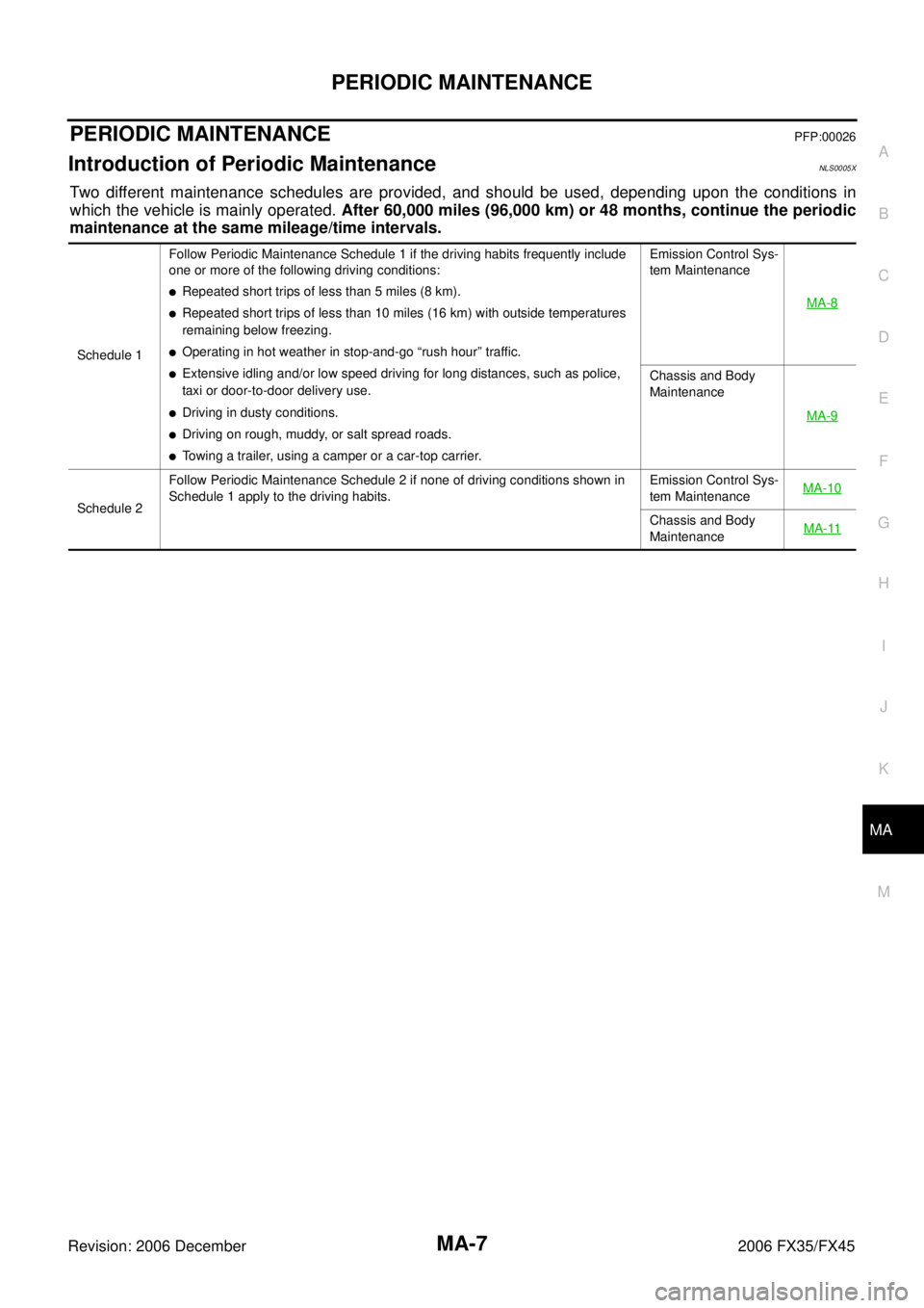
Two different maintenance schedules are provided, and should be used, depending upon the conditions in
which the vehicle is mainly operated. After 60,000 miles (96,000 km) or 48 months, continue the periodic
maintenance at the same mileage/time intervals.
Schedule 1 Follow Periodic Maintenance Schedule 1 if the driving habits frequently include
one or more of the following driving conditions:
�Repeated short trips of less than 5 miles (8 km).
�Repeated short trips of less than 10 miles (16 km) with outside temperatures
remaining below freezing.
�Operating in hot weather in stop-and-go “rush hour” traffic.
�Extensive idling and/or low speed driving for long distances, such as police,
taxi or door-to-door delivery use.
�Driving in dusty conditions.
�Driving on rough, muddy, or salt spread roads.
�Towing a trailer, using a camper or a car-top carrier. Emission Control Sys-
tem Maintenance
MA-8
Chassis and Body
Maintenance
MA-9
Schedule 2 Follow Periodic Maintenance Schedule 2 if none of driving conditions shown in
Schedule 1 apply to the driving habits. Emission Control Sys-
tem Maintenance MA-10Chassis and Body
Maintenance MA-11
Page 3810 of 4462
MA-10
PERIODIC MAINTENANCE
Revision: 2006 December 2006 FX35/FX45
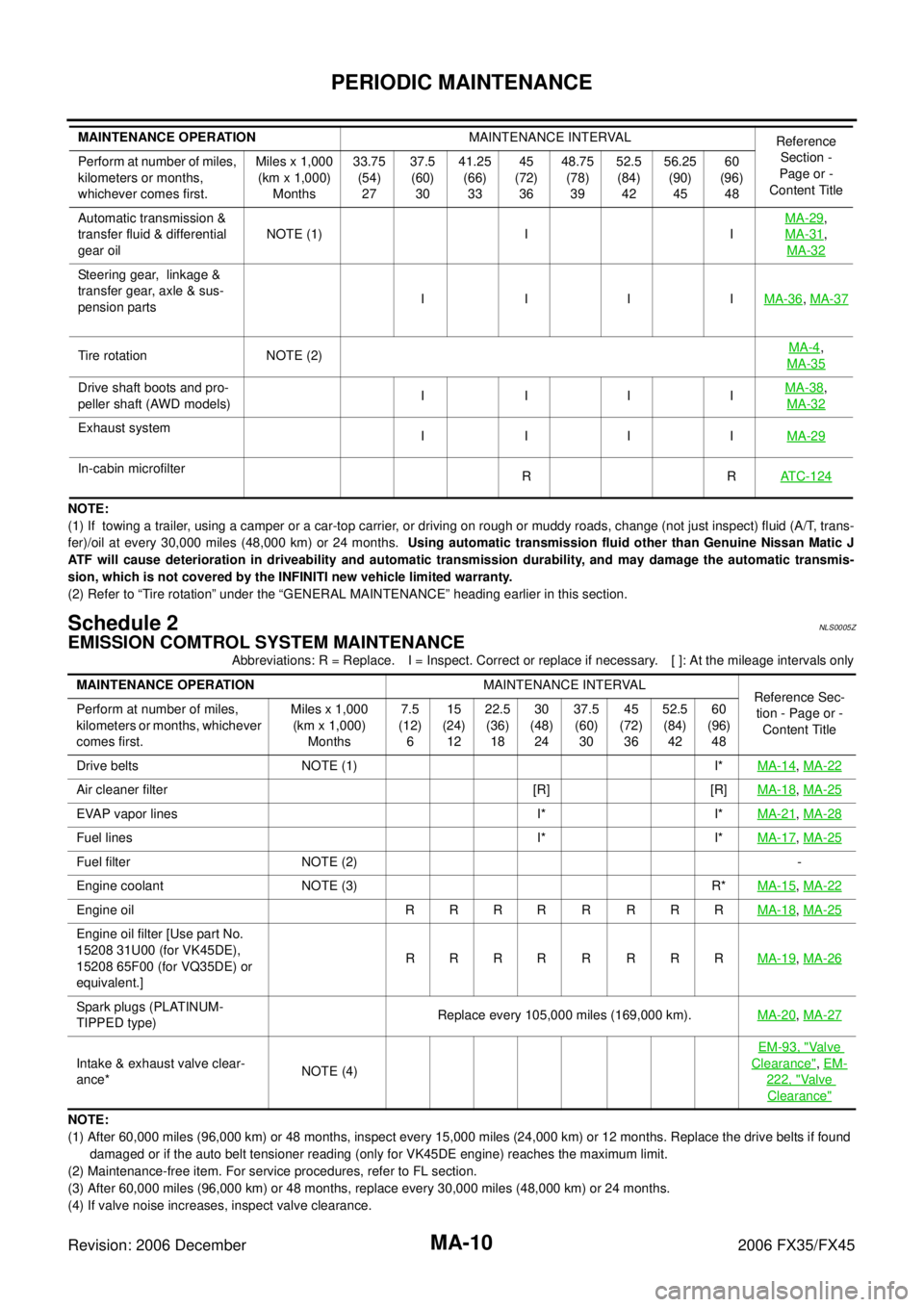
NOTE:
(1) If towing a trailer, using a camper or a car-top carrier, or driving on rough or muddy roads, change (not just inspect) fl uid (A/T, trans-
fer)/oil at every 30,000 miles (48,000 km) or 24 months. Using automatic transmission fluid other than Genuine Nissan Matic J
ATF will cause deterioration in driveability and automatic transmission durability, and may damage the automatic transmis-
sion, which is not covered by the INFINITI new vehicle limited warranty.
(2) Refer to “Tire rotation” under the “GENERAL MAINTENANCE” heading earlier in this section.
Schedule 2NLS0005Z
EMISSION COMTROL SYSTEM MAINTENANCE
Abbreviations: R = Replace. I = Inspect. Correct or replace if necessary. [ ]: At the mileage intervals only
NOTE:
(1) After 60,000 miles (96,000 km) or 48 months, inspect every 15,000 miles (24,000 km) or 12 months. Replace the drive belts i f found
damaged or if the auto belt tensioner reading (only for VK45DE engine) reaches the maximum limit.
(2) Maintenance-free item. For service procedures, refer to FL section.
(3) After 60,000 miles (96,000 km) or 48 months, replace every 30,000 miles (48,000 km) or 24 months.
(4) If valve noise increases, inspect valve clearance. Automatic transmission &
transfer fluid & differential
gear oil NOTE (1) I I
MA-29
,
MA-31
,
MA-32
Steering gear, linkage &
transfer gear, axle & sus-
pension parts I III
MA-36
, MA-37
Tire rotation NOTE (2) MA-4,
MA-35
Drive shaft boots and pro-
peller shaft (AWD models) I III MA-38,
MA-32
Exhaust system I III MA-29
In-cabin microfilter
RR ATC-124
MAINTENANCE OPERATION MAINTENANCE INTERVAL
Reference
Section -
Page or -
Content Title
Perform at number of miles,
kilometers or months,
whichever comes first. Miles x 1,000
(km x 1,000) Months 33.75
(54) 27 37.5
(60) 30 41.25
(66) 33 45
(72) 36 48.75
(78) 39 52.5
(84) 42 56.25
(90) 45 60
(96) 48
MAINTENANCE OPERATION MAINTENANCE INTERVAL
Reference Sec-
tion - Page or - Content Title
Perform at number of miles,
kilometers or months, whichever
comes first. Miles x 1,000
(km x 1,000) Months 7.5
(12) 6 15
(24) 12 22.5
(36) 18 30
(48) 24 37.5
(60) 30 45
(72) 36 52.5
(84) 42 60
(96) 48
Drive belts NOTE (1) I* MA-14
, MA-22
Air cleaner filter [R] [R] MA-18, MA-25
EVAP vapor lines I* I* MA-21, MA-28
Fuel lines I* I* MA-17, MA-25
Fuel filter NOTE (2) -
Engine coolant NOTE (3) R* MA-15
, MA-22
Engine oil R R R R R R R R MA-18, MA-25
Engine oil filter [Use part No.
15208 31U00 (for VK45DE),
15208 65F00 (for VQ35DE) or
equivalent.] RRRR R RRR
MA-19
, MA-26
Spark plugs (PLATINUM-
TIPPED type) Replace every 105,000 miles (169,000 km).
MA-20, MA-27
Intake & exhaust valve clear-
ance* NOTE (4) EM-93, "
Va l v e
Clearance",
EM-
222, "Va l v e
Clearance"
Page 3880 of 4462
PG-28
IPDM E/R (INTELLIGENT POWER DISTRIBUTION MODULE ENGINE ROOM)
Revision: 2006 December 2006 FX35/FX45
Removal and Installation of IPDM E/RNKS003GL
REMOVAL
1. Remove battery. Refer to SC-7, "Removal and Installation" .
2. Remove IPDM E/R cover A. While pressing pawl on backside of IPDM E/R cover B toward vehicle front to unlock, lift up IPDM E/
R.
3. While pressing pawls on right and left side of IPDM E/R, remove IPDM E/R cover B from IPDM E/R.
4. Remove harness connector from IPDM E/R.
INSTALLATION
Installation is the reverse order of removal.
SKIA4968E
SKIA1902E
SKIA4969E
Page 3945 of 4462
REAR PROPELLER SHAFT PR-11
C E F
G H
I
J
K L
M A
B
PR
Revision: 2006 December 2006 FX35/FX45
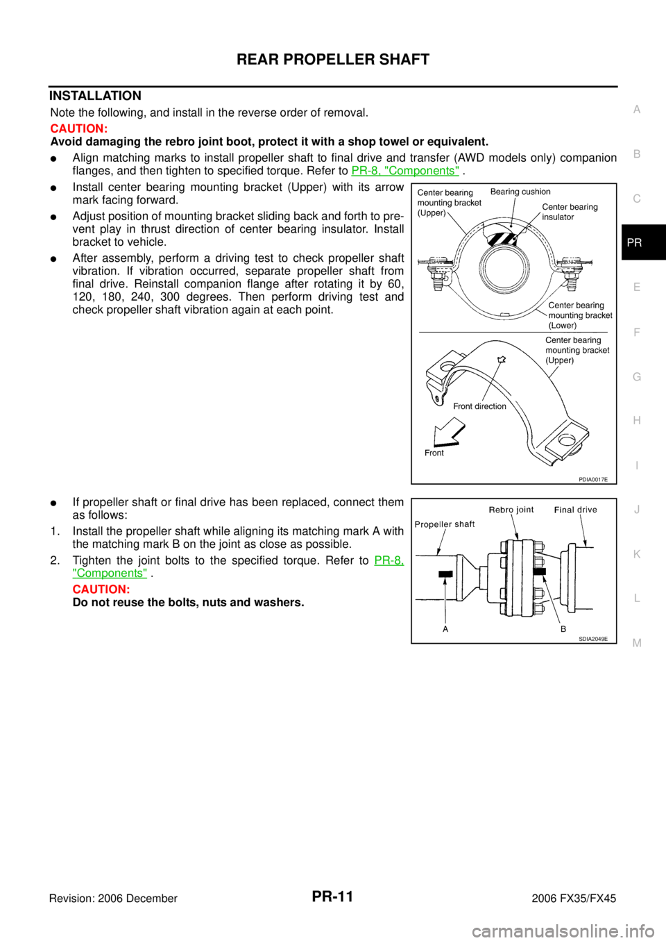
INSTALLATION
Note the following, and install in the reverse order of removal.
CAUTION:
Avoid damaging the rebro joint boot, protect it with a shop towel or equivalent.
�Align matching marks to install propeller shaft to final drive and transfer (AWD models only) companion
flanges, and then tighten to specified torque. Refer to PR-8, "
Components" .
�Install center bearing mounting bracket (Upper) with its arrow
mark facing forward.
�Adjust position of mounting bracket sliding back and forth to pre-
vent play in thrust direction of center bearing insulator. Install
bracket to vehicle.
�After assembly, perform a driving test to check propeller shaft
vibration. If vibration occurred, separate propeller shaft from
final drive. Reinstall companion flange after rotating it by 60,
120, 180, 240, 300 degrees. Then perform driving test and
check propeller shaft vibration again at each point.
�If propeller shaft or final drive has been replaced, connect them
as follows:
1. Install the propeller shaft while aligning its matching mark A with the matching mark B on the joint as close as possible.
2. Tighten the joint bolts to the specified torque. Refer to PR-8,
"Components" .
CAUTION:
Do not reuse the bolts, nuts and washers.
PDIA0017E
SDIA2049E
Page 3952 of 4462
PS-4
PRECAUTIONS
Revision: 2006 December 2006 FX35/FX45
�Use nylon cloth or paper towels to clean the parts; common shop rags can leave lint that might interfere
with their operation.
�Before inspection or reassembly, carefully clean all parts with a general purpose, non-flammable solvent.
�Before assembly, apply a coat of recommended Genuine NISSAN PSF or equivalent to hydraulic parts.
Petroleum jelly may be applied to O-rings and seals. Do not use any grease.
�Replace all gaskets, seals and O-rings. Avoid damaging O-rings, seals and gaskets during installation.
Perform functional tests whenever designated.
Page 3981 of 4462
POWER STEERING OIL PUMP PS-33
C
D E
F
H I
J
K L
M A
B
PS
Revision: 2006 December 2006 FX35/FX45
3. Install flow control valve A, flow control valve spring and flow control valve B assembly to locations shown in the figure.
4. Match dowel pin A on flow control valve A, shown in the figure, with cutout B of front side plate and then install front side plate to
body assembly.
5. Install cam ring onto front side plate with smaller slit of cam ring facing body assembly.
6. Install pulley to body assembly.
CAUTION:
When installing pulley, be careful not to scratch oil seal.
7. Face the side of rotor with punch mark towards rear cover, and attach rotor to pulley shaft.
SGIA0526E
SGIA0528E
SGIA0623E
SGIA0529E
Page 4005 of 4462
REAR DRIVE SHAFT RAX-11
C E F
G H
I
J
K L
M A
B
RAX
Revision: 2006 December 2006 FX35/FX45
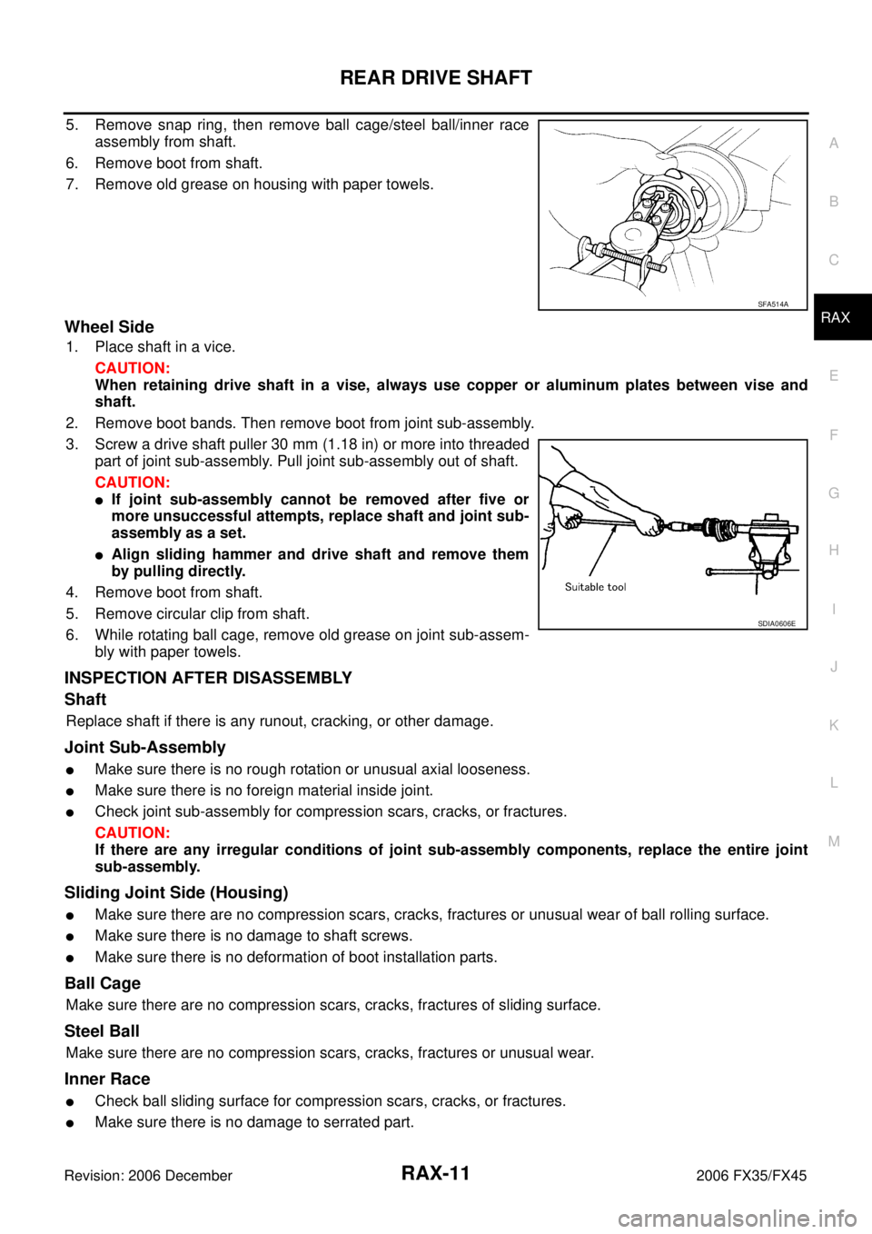
5. Remove snap ring, then remove ball cage/steel ball/inner race assembly from shaft.
6. Remove boot from shaft.
7. Remove old grease on housing with paper towels.
Wheel Side
1. Place shaft in a vice. CAUTION:
When retaining drive shaft in a vise, always use copper or aluminum plates between vise and
shaft.
2. Remove boot bands. Then remove boot from joint sub-assembly.
3. Screw a drive shaft puller 30 mm (1.18 in) or more into threaded part of joint sub-assembly. Pull joint sub-assembly out of shaft.
CAUTION:
�If joint sub-assembly cannot be removed after five or
more unsuccessful attempts, replace shaft and joint sub-
assembly as a set.
�Align sliding hammer and drive shaft and remove them
by pulling directly.
4. Remove boot from shaft.
5. Remove circular clip from shaft.
6. While rotating ball cage, remove old grease on joint sub-assem- bly with paper towels.
INSPECTION AFTER DISASSEMBLY
Shaft
Replace shaft if there is any runout, cracking, or other damage.
Joint Sub-Assembly
�Make sure there is no rough rotation or unusual axial looseness.
�Make sure there is no foreign material inside joint.
�Check joint sub-assembly for compression scars, cracks, or fractures.
CAUTION:
If there are any irregular conditions of joint sub-assembly components, replace the entire joint
sub-assembly.
Sliding Joint Side (Housing)
�Make sure there are no compression scars, cracks, fractures or unusual wear of ball rolling surface.
�Make sure there is no damage to shaft screws.
�Make sure there is no deformation of boot installation parts.
Ball Cage
Make sure there are no compression scars, cracks, fractures of sliding surface.
Steel Ball
Make sure there are no compression scars, cracks, fractures or unusual wear.
Inner Race
�Check ball sliding surface for compression scars, cracks, or fractures.
�Make sure there is no damage to serrated part.
SFA514A
SDIA0606E
Page 4239 of 4462
FRONT SEAT SE-101
C
D E
F
G H
J
K L
M A
B
SE
Revision: 2006 December 2006 FX35/FX45
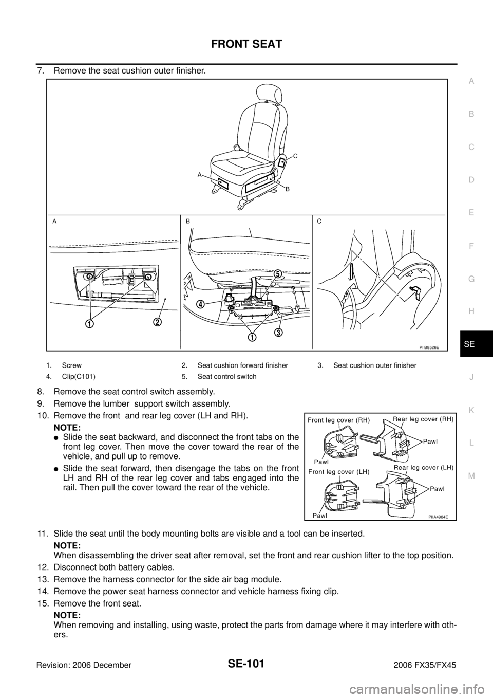
7. Remove the seat cushion outer finisher.
8. Remove the seat control switch assembly.
9. Remove the lumber support switch assembly.
10. Remove the front and rear leg cover (LH and RH). NOTE:
�Slide the seat backward, and disconnect the front tabs on the
front leg cover. Then move the cover toward the rear of the
vehicle, and pull up to remove.
�Slide the seat forward, then disengage the tabs on the front
LH and RH of the rear leg cover and tabs engaged into the
rail. Then pull the cover toward the rear of the vehicle.
11. Slide the seat until the body mounting bolts are visible and a tool can be inserted. NOTE:
When disassembling the driver seat after removal, set the front and rear cushion lifter to the top position.
12. Disconnect both battery cables.
13. Remove the harness connector for the side air bag module.
14. Remove the power seat harness connector and vehicle harness fixing clip.
15. Remove the front seat. NOTE:
When removing and installing, using waste, protect the parts from damage where it may interfere with oth-
ers.
PIIB8526E
1. Screw 2. Seat cushion forward finisher 3. Seat cushion outer finisher
4. Clip(C101) 5. Seat control switch
PIIA4984E