Page 4211 of 4462

AUTOMATIC DRIVE POSITIONER SE-73
C
D E
F
G H
J
K L
M A
B
SE
Revision: 2006 December 2006 FX35/FX45
Check Telescopic Switch CircuitNIS001VQ
1. CHECK FUNCTION
With CONSULT-II
With “TELESCO SW-FR, TELESCO SW-RR” on the DATA MONITOR, operate the ADP steering switch to
check ON/OFF operation.
Without CONSULT-II
1. Turn ignition switch OFF.
2. Telescopic switch operate, check voltage between automatic drive positioner control unit connector and ground.
OK or NG
OK >> Telescopic switch circuit is OK.
NG >> GO TO 2.
2. CHECK TELESCOPIC CIRCUIT HARNESS CONTINUITY
1. Disconnect automatic drive positioner control unit connector and ADP steering switch connector.
2. Check continuity between automatic drive positioner control unit connector M49 terminals 11, 27 and ADP steering switch con-
nector M13 terminals 4, 5.
3. Check continuity between automatic drive positioner control unit connector M49 terminals 11, 27 and ground.
OK or NG
OK >> GO TO 3.
NG >> Repair or replace harness between automatic drive positioner control unit and ADP steering switch.
Monitor item
[OPERATION or UNIT] Contents
TELESCO SW-FR “ON/OFF” (ON/OFF) status judged from the telescoping
switch (FR) signal is displayed.
TELESCO SW-RR “ON/OFF” (ON/OFF) status judged from the telescoping
switch (RR) signal is displayed.
PIIA0315E
Connector Terminals
(Wire color) Telescopic switch condition Voltage (V)
(Approx.)
(+) (–)
M49 11 ( B R )
Ground FORWARD 0
Other than above 5
27 (LG) BACKWARD 0
Other than above 5
PIIA5073E
11 (BR) – 5 (BR) : Continuity should exist.
27 (LG) – 4 (LG) : Continuity should exist.
11 (BR) – Ground : Continuity should not exist.
27 (LG) – Ground : Continuity should not exist.
PIIA5071E
Page 4212 of 4462
SE-74
AUTOMATIC DRIVE POSITIONER
Revision: 2006 December 2006 FX35/FX45
3. CHECK TELESCOPIC SWITCH
ADP steering switch operate, check continuity between ADP steering switch connector M13 terminal 4, 5 and
1.
OK or NG
OK >> GO TO 4.
NG >> Replace ADP steering switch.
4. CHECK ADP STEERING SWITCH GROUND CIRCUIT
Check continuity between ADP steering switch connector M13 termi-
nal 1 and ground.
OK or NG
OK >> Check the condition of the harness and connector.
NG >> Replace or replace harness between ADP steering
switch and ground.
Connector Terminal ADP steering switch condition Continuity
M13 5
1 FORWARD Yes
Other than above No
4 BACKWARD Yes
Other than above No
PIIA4481E
1 (B) – Ground : Continuity should exist.
PIIA3308E
Page 4213 of 4462

AUTOMATIC DRIVE POSITIONER SE-75
C
D E
F
G H
J
K L
M A
B
SE
Revision: 2006 December 2006 FX35/FX45
Check Tilt Switch CircuitNIS001VR
1. CHECK FUNCTION
With CONSULT-II
With “TILT SW-UP, TILT SW-DOWN” on the DATA MONITOR, operate the ADP steering switch to check ON/
OFF operation.
Without CONSULT-II
1. Turn ignition switch OFF.
2. Tilt switch operate, check voltage between automatic drive positioner control unit connector and ground.
OK or NG
OK >> Tilt switch circuit is OK.
NG >> GO TO 2.
2. CHECK TILT SWITCH CIRCUIT HARNESS CONTINUITY
1. Disconnect automatic drive positioner control unit connector and ADP steering switch connector.
2. Check continuity between automatic drive positioner control unit connector M49 terminals 1, 17 and ADP steering switch connec-
tor M13 terminals 2, 3.
3. Check continuity between automatic drive positioner control unit connector M49 terminals 1, 17 and ground.
OK or NG
OK >> GO TO 3.
NG >> Repair or replace harness between automatic drive positioner control unit and ADP steering
switch.
Monitor item
[OPERATION or UNIT] Contents
TILT SW-UP “ON/OFF” (ON/OFF) status judged from the tilt switch
(UP) signal is displayed.
TILT SW-DOWN “ON/OFF” (ON/OFF) status judged from the tilt switch
(DOWN) signal is displayed.
PIIA0315E
Connector Terminals
(Wire color) Tilt switch condition Voltage (V)
(Approx.)
(+) (–)
M49 1 (R)
Ground UP 0
Other than above 5
17 (R/B) DOWN 0
Other than above 5
PIIA5074E
1 (R) – 2 (R) : Continuity should exist.
17 (R/B) – 3 (R/B) : Continuity should exist.
1 (R) – Ground : Continuity should not exist.
17 (R/B) – Ground : Continuity should not exist.
PIIA5072E
Page 4214 of 4462
SE-76
AUTOMATIC DRIVE POSITIONER
Revision: 2006 December 2006 FX35/FX45
3. CHECK ADP TILT STEERING SWITCH
ADP steering switch operate, check continuity between ADP steering switch.
OK or NG
OK >> GO TO 6.
NG >> Replace ADP steering switch.
4. CHECK ADP STEERING SWITCH GROUND CIRCUIT
Check continuity between ADP steering switch connector M13 termi-
nal 1 and ground.
OK or NG
OK >> Check the condition of the harness and connector.
NG >> Repair or replace harness between ADP steering switch and ground.
Connector Terminal ADP steering switch condition Continuity
M13 2
1 UP Yes
Other than above No
3 DOWN Yes
Other than above No
PIIA4482E
1 (B) – Ground : Continuity should exist.
PIIA3310E
Page 4251 of 4462
 “AIR BAG” and “SEAT
BE")
PRECAUTIONS SRS-3
C
D E
F
G
I
J
K L
M A
B
SRS
Revision: 2006 December 2006 FX35/FX45
PRECAUTIONSPFP:00001
Precautions for Supplemental Restraint System (SRS) “AIR BAG” and “SEAT
BELT PRE-TENSIONER”
NHS00073
The Supplemental Restraint System such as “AIR BAG” and “SEAT BELT PRE-TENSIONER”, used along
with a front seat belt, helps to reduce the risk or severity of injury to the driver and front passenger for certain
types of collision. This system includes seat belt switch inputs and dual stage front air bag modules. The SRS
system uses the seat belt switches to determine the front air bag deployment, and may only deploy one front
air bag, depending on the severity of a collision and whether the front occupants are belted or unbelted.
Information necessary to service the system safely is included in the SRS and SB section of this Service Man-
ual.
WARNING:
�To avoid rendering the SRS inoperative, which could increase the risk of personal injury or death
in the event of a collision which would result in air bag inflation, all maintenance must be per-
formed by an authorized NISSAN/INFINITI dealer.
�Improper maintenance, including incorrect removal and installation of the SRS, can lead to per-
sonal injury caused by unintentional activation of the system. For removal of Spiral Cable and Air
Bag Module, see the SRS section.
�Do not use electrical test equipment on any circuit related to the SRS unless instructed to in this
Service Manual. SRS wiring harnesses can be identified by yellow and/or orange harnesses or
harness connectors.
Precautions for SRS “AIR BAG” and “SEAT BELT PRE-TENSIONER” ServiceNHS00074
�Do not use electrical test equipment to check SRS circuits unless instructed to in this Service Manual.
�Before servicing the SRS, turn ignition switch OFF, disconnect both battery cables and wait at least 3 min-
utes.
For approximately 3 minutes after the cables are removed, it is still possible for the air bag and seat belt
pre-tensioner to deploy. Therefore, do not work on any SRS connectors or wires until at least 3 minutes
have passed.
�Diagnosis sensor unit must always be installed with their arrow marks “ ⇐” pointing towards the front of the
vehicle for proper operation. Also check diagnosis sensor unit for cracks, deformities or rust before instal-
lation and replace as required.
�The spiral cable must be aligned with the neutral position since its rotations are limited. Do not turn steer-
ing wheel and column after removal of steering gear.
�Handle air bag module carefully. Always place driver and front passenger air bag modules with the pad
side facing upward and seat mounted front side air bag module standing with the stud bolt side facing
down.
�Conduct self-diagnosis to check entire SRS for proper function after replacing any components.
�After air bag inflates, the front instrument panel assembly should be replaced if damaged.
�Always replace instrument panel pad following front passenger air bag deployment.
�Disposal, recycling, and transportation of air bag modules and seat belt pre-tensioners should be per-
formed in compliance with applicable federal, state and local laws and regulations.
Occupant Classification System PrecautionNHS0009N
Replace occupant classification system control unit and passenger front seat cushion as an assembly.
Refer to Refer to Service Manual .
Page 4286 of 4462
SRS-38
DRIVER AIR BAG MODULE
Revision: 2006 December 2006 FX35/FX45
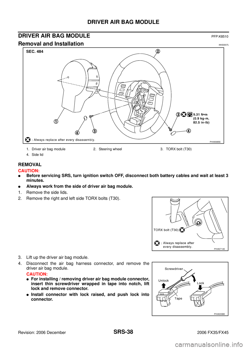
DRIVER AIR BAG MODULEPFP:K8510
Removal and InstallationNHS0007L
REMOVAL
CAUTION:
�Before servicing SRS, turn ignition switch OFF, disconnect both battery cables and wait at least 3
minutes.
�Always work from the side of driver air bag module.
1. Remove the side lids.
2. Remove the right and left side TORX bolts (T30).
3. Lift up the driver air bag module.
4. Disconnect the air bag harness connector, and remove the driver air bag module.
CAUTION:
�For installing / removing driver air bag module connector,
insert thin screwdriver wrapped in tape into notch, lift
lock and remove connector.
�Install connector with lock raised, and push lock into
connector.
PHIA0685E
1. Driver air bag module 2. Steering wheel 3. TORX bolt (T30)
4. Side lid
PHIA0714E
PHIA0308E
Page 4288 of 4462

SRS-40
SPIRAL CABLE
Revision: 2006 December 2006 FX35/FX45
SPIRAL CABLEPFP:25554
Removal and InstallationNHS0007M
REMOVAL
CAUTION:
Before servicing SRS, turn ignition switch OFF, disconnect both battery cables and wait at least 3 min-
utes.
1. Remove driver air bag module. Refer to SRS-38, "
Removal and Installation" .
2. Set the steering wheel in the neutral position.
3. Removal steering wheel. Refer to PS-11, "
Removal and Installation" .
4. Remove steering column covers. Refer to IP-11, "
Removal and Installation" .
5. Loosen the spiral cable fixing screws, and then remove the spiral cable.
CAUTION:
�Do not disassemble spiral cable.
�Do not apply lubricant to the spiral cable.
6. Disconnect the horn switch connector, and then the spiral cable connector.
CAUTION:
�Do not tap or bump the steering wheel.
�Also, with the steering linkage disconnected the cable
may snap by turning the steering wheel beyond the lim-
ited number of turns.
7. Remove the wiper washer switch and lighting switch from the spiral cable.
INSTALLATION
Install in the reverse order of removal.
PHIA1336E
1. Steering wheel 2. Spiral cable 3. Driver air bag module connector
4. Screw 5. Wiper and washer switch 6. Lighting and turn signal switch
7. Steering column assembly 8. Steering column cover (upper) 9. Steering column cover (lower)
SHIA0193E
Page 4289 of 4462
SPIRAL CABLE SRS-41
C
D E
F
G
I
J
K L
M A
B
SRS
Revision: 2006 December 2006 FX35/FX45
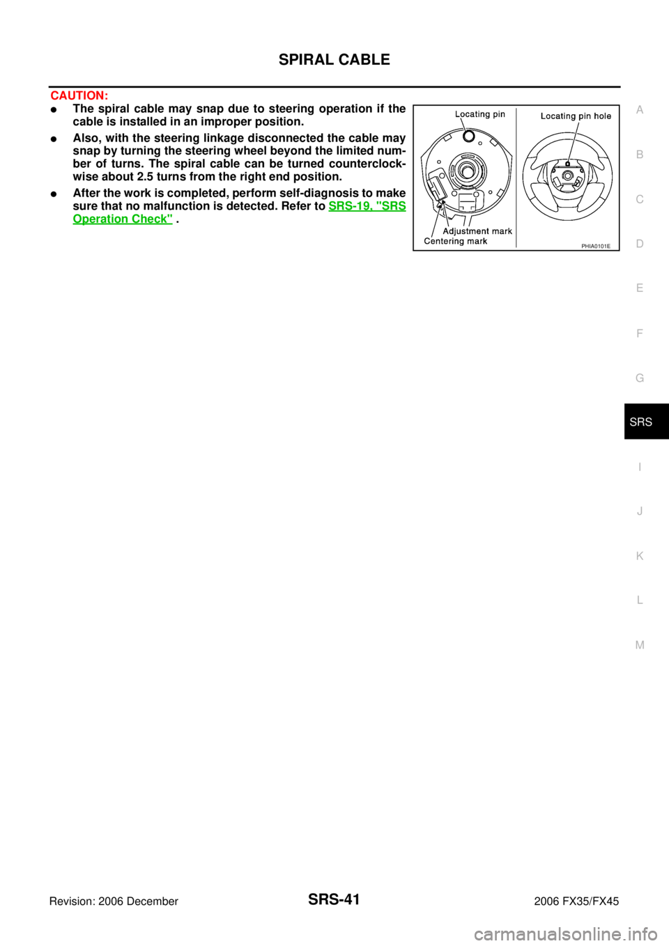
CAUTION:
�The spiral cable may snap due to steering operation if the
cable is installed in an improper position.
�Also, with the steering linkage disconnected the cable may
snap by turning the steering wheel beyond the limited num-
ber of turns. The spiral cable can be turned counterclock-
wise about 2.5 turns from the right end position.
�After the work is completed, perform self-diagnosis to make
sure that no malfunction is detected. Refer to SRS-19, "
SRS
Operation Check" .
PHIA0101E