Page 3835 of 4462
CHASSIS AND BODY MAINTENANCE MA-35
C
D E
F
G H
I
J
K
M A
B
MA
Revision: 2006 December 2006 FX35/FX45
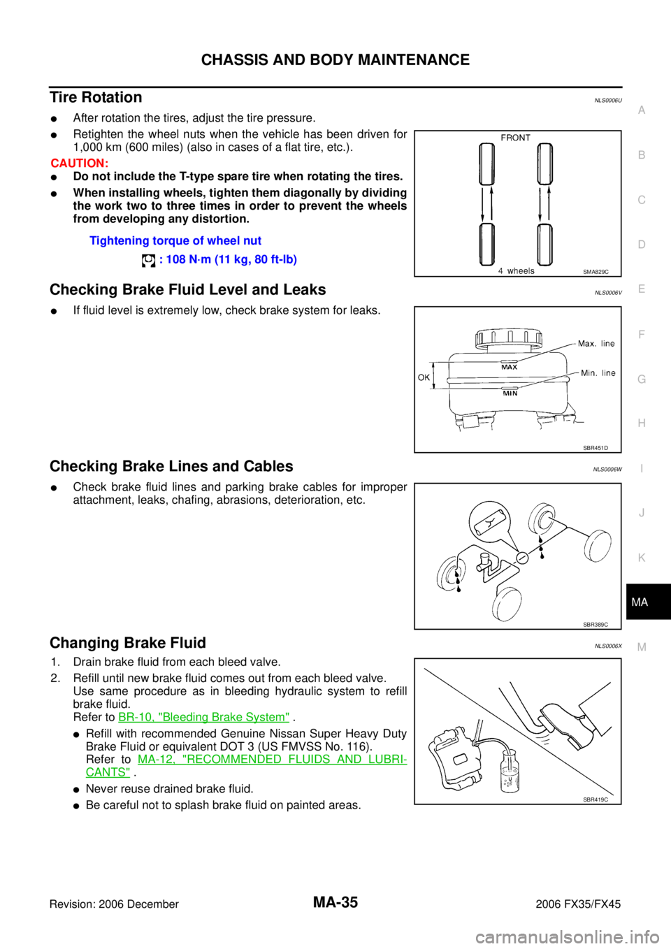
Tire RotationNLS0006U
�After rotation the tires, adjust the tire pressure.
�Retighten the wheel nuts when the vehicle has been driven for
1,000 km (600 miles) (also in cases of a flat tire, etc.).
CAUTION:
�Do not include the T-type spare tire when rotating the tires.
�When installing wheels, tighten them diagonally by dividing
the work two to three times in order to prevent the wheels
from developing any distortion.
Checking Brake Fluid Level and LeaksNLS0006V
�If fluid level is extremely low, check brake system for leaks.
Checking Brake Lines and CablesNLS0006W
�Check brake fluid lines and parking brake cables for improper
attachment, leaks, chafing, abrasions, deterioration, etc.
Changing Brake FluidNLS0006X
1. Drain brake fluid from each bleed valve.
2. Refill until new brake fluid comes out from each bleed valve. Use same procedure as in bleeding hydraulic system to refill
brake fluid.
Refer to BR-10, "
Bleeding Brake System" .
�Refill with recommended Genuine Nissan Super Heavy Duty
Brake Fluid or equivalent DOT 3 (US FMVSS No. 116).
Refer to MA-12, "
RECOMMENDED FLUIDS AND LUBRI-
CANTS" .
�Never reuse drained brake fluid.
�Be careful not to splash brake fluid on painted areas. Tightening torque of wheel nut
: 108 N·m (11 kg, 80 ft-lb)
SMA829C
SBR451D
SBR389C
SBR419C
Page 3937 of 4462
NOISE, VIBRATION AND HARSHNESS (NVH) TROUBLESHOOTING PR-3
C E F
G H
I
J
K L
M A
B
PR
Revision: 2006 December 2006 FX35/FX45
NOISE, VIBRATION AND HARSHNESS (NVH) TROUBLESHOOTINGPFP:00003
NVH Troubleshooting ChartNDS000AS
Use the chart below to help you find the cause of the symptom. If necessary, repair or replace these parts.
× : Applicable
Reference page
Front
PR-4—
—
—
—
PR-4PR-5
NVH in FFD and RFD section
NVH in FAX, RAX, FSU, and RSU section
NVH in WT section
NVH in WT section
NVH in RAX section
NVH in BR section
NVH in PS section
RearPR-7PR-11—
PR-8—
PR-7PR-10
Possible cause and SUSPECTED PARTS
Uneven rotating torque
Center bearing improper installation
Excessive center bearing axial end play
Center bearing mounting (insulator) cracks, damage or deterioration
Excessive joint angle
Rotation imbalance
Excessive runout
DIFFERENTIAL
AXLE AND SUSPENSION
TIRES
ROAD WHEEL
DRIVE SHAFT
BRAKES
STEERING
Symptom Noise
××××××××××××××
Shake × × ××××××
Vibration ××××××× ×× × ×
Page 3955 of 4462
NOISE, VIBRATION AND HARSHNESS (NVH) TROUBLESHOOTING PS-7
C
D E
F
H I
J
K L
M A
B
PS
Revision: 2006 December 2006 FX35/FX45
NOISE, VIBRATION AND HARSHNESS (NVH) TROUBLESHOOTINGPFP:00003
NVH Troubleshooting ChartNGS000BS
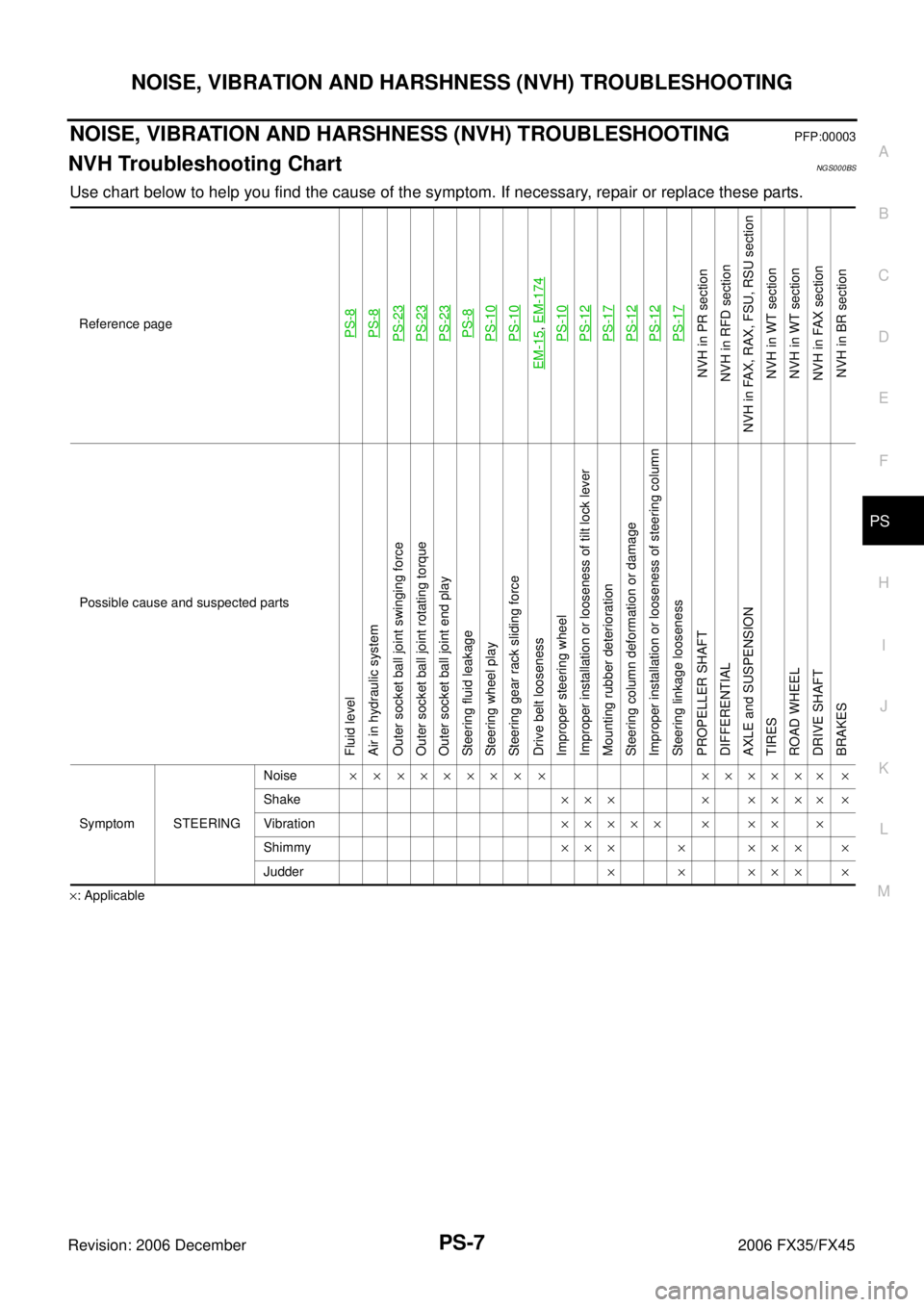
Use chart below to help you find the cause of the symptom. If necessary, repair or replace these parts.
× : Applicable Reference page
PS-8PS-8PS-23PS-23PS-23PS-8PS-10PS-10
EM-15
,
EM-174PS-10PS-12PS-17PS-12PS-12PS-17
NVH in PR section
NVH in RFD section
NVH in FAX, RAX, FSU, RSU section NVH in WT section
NVH in WT section
NVH in FAX section
NVH in BR section
Possible cause and suspected parts
Fluid level
Air in hydraulic system
Outer socket ball joint swinging force
Outer socket ball joint rotating torque
Outer socket ball joint end play
Steering fluid leakage
Steering wheel play
Steering gear rack sliding force
Drive belt looseness
Improper steering wheel
Improper installation or looseness of tilt lock lever
Mounting rubber deterioration
Steering column deformation or damage
Improper installation or looseness of steering column
Steering linkage looseness
PROPELLER SHAFT
DIFFERENTIAL
AXLE and SUSPENSION
TIRES
ROAD WHEEL
DRIVE SHAFT
BRAKES
Symptom STEERING Noise
× × ××××× × × ×××××× ×
Shake ××× × ×××× ×
Vibration ××××× × ×× ×
Shimmy ××× × ××× ×
Judder ××××××
Page 3958 of 4462
PS-10
STEERING WHEEL
Revision: 2006 December 2006 FX35/FX45
STEERING WHEELPFP:48430
On-Vehicle Inspection and ServiceNGS000BW
CHECKING CONDITION OF INSTALLATION
�Check installation condition of steering gear assembly, front suspension, axle and steering column.
�Check if movement exists when steering wheel is moved up and down, to the left and right and to the axial
direction.
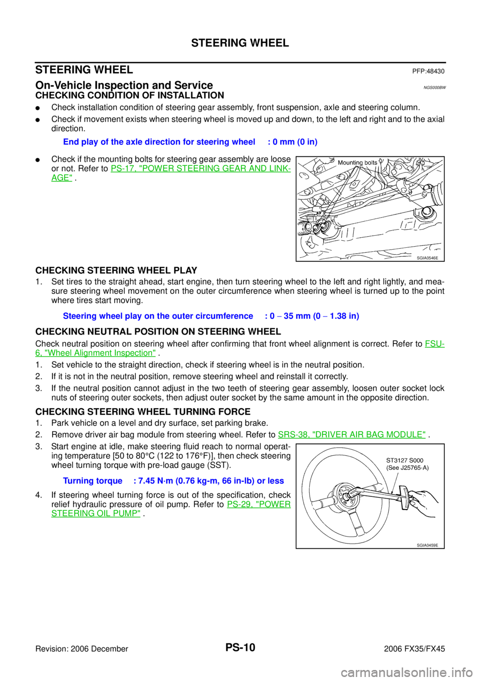
�Check if the mounting bolts for steering gear assembly are loose
or not. Refer to PS-17, "
POWER STEERING GEAR AND LINK-
AGE" .
CHECKING STEERING WHEEL PLAY
1. Set tires to the straight ahead, start engine, then turn steering wheel to the left and right lightly, and mea-
sure steering wheel movement on the outer circumference when steering wheel is turned up to the point
where tires start moving.
CHECKING NEUTRAL POSITION ON STEERING WHEEL
Check neutral position on steering wheel after confirming that front wheel alignment is correct. Refer to FSU-
6, "Wheel Alignment Inspection" .
1. Set vehicle to the straight direction, check if steering wheel is in the neutral position.
2. If it is not in the neutral position, remove steering wheel and reinstall it correctly.
3. If the neutral position cannot adjust in the two teeth of steering gear assembly, loosen outer socket lock nuts of steering outer sockets, then adjust outer socket by the same amount in the opposite direction.
CHECKING STEERING WHEEL TURNING FORCE
1. Park vehicle on a level and dry surface, set parking brake.
2. Remove driver air bag module from steering wheel. Refer to SRS-38, "
DRIVER AIR BAG MODULE" .
3. Start engine at idle, make steering fluid reach to normal operat- ing temperature [50 to 80 °C (122 to 176 °F)], then check steering
wheel turning torque with pre-load gauge (SST).
4. If steering wheel turning force is out of the specification, check relief hydraulic pressure of oil pump. Refer to PS-29, "
POWER
STEERING OIL PUMP" .
End play of the axle direction for steering wheel : 0 mm (0 in)
SGIA0546E
Steering wheel play on the outer circumference : 0
− 35 mm (0 − 1.38 in)
Turning torque : 7.45 N·m (0.76 kg-m, 66 in-lb) or less
SGIA0459E
Page 3962 of 4462
PS-14
STEERING COLUMN
Revision: 2006 December 2006 FX35/FX45
INSPECTION AFTER REMOVAL
�Check if there is something wrong with jacket tube of steering column assembly and collar etc. And then if
they are damaged, replace with new one.
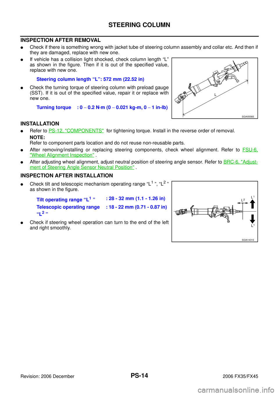
�If vehicle has a collision light shocked, check column length “L”
as shown in the figure. Then if it is out of the specified value,
replace with new one.
�Check the turning torque of steering column with preload gauge
(SST). If it is out of the specified value, repair it or replace with
new one.
INSTALLATION
�Refer to PS-12, "COMPONENTS" for tightening torque. Install in the reverse order of removal.
NOTE:
Refer to component parts location and do not reuse non-reusable parts.
�After removing/installing or replacing steering components, check wheel alignment. Refer to FSU-6,
"Wheel Alignment Inspection" .
�After adjusting wheel alignment, adjust neutral position of steering angle sensor. Refer to BRC-6, "Adjust-
ment of Steering Angle Sensor Neutral Position" .
INSPECTION AFTER INSTALLATION
�Check tilt and telescopic mechanism operating range “L1 ”, “L2 ”
as shown in the figure.
�Check if steering wheel operation can turn to the end of the left
and right smoothly. Steering column length “L”: 572 mm (22.52 in)
Turning torque : 0 − 0.2 N·m (0 − 0.021 kg-m, 0 − 1 in-lb)
SGIA0556E
Tilt operating range “L1 ” : 28 - 32 mm (1.1 - 1.26 in)
Telescopic operating range
“L
2 ” : 18 - 22 mm (0.71 - 0.87 in)
SGIA1431E
Page 3966 of 4462
PS-18
POWER STEERING GEAR AND LINKAGE
Revision: 2006 December 2006 FX35/FX45
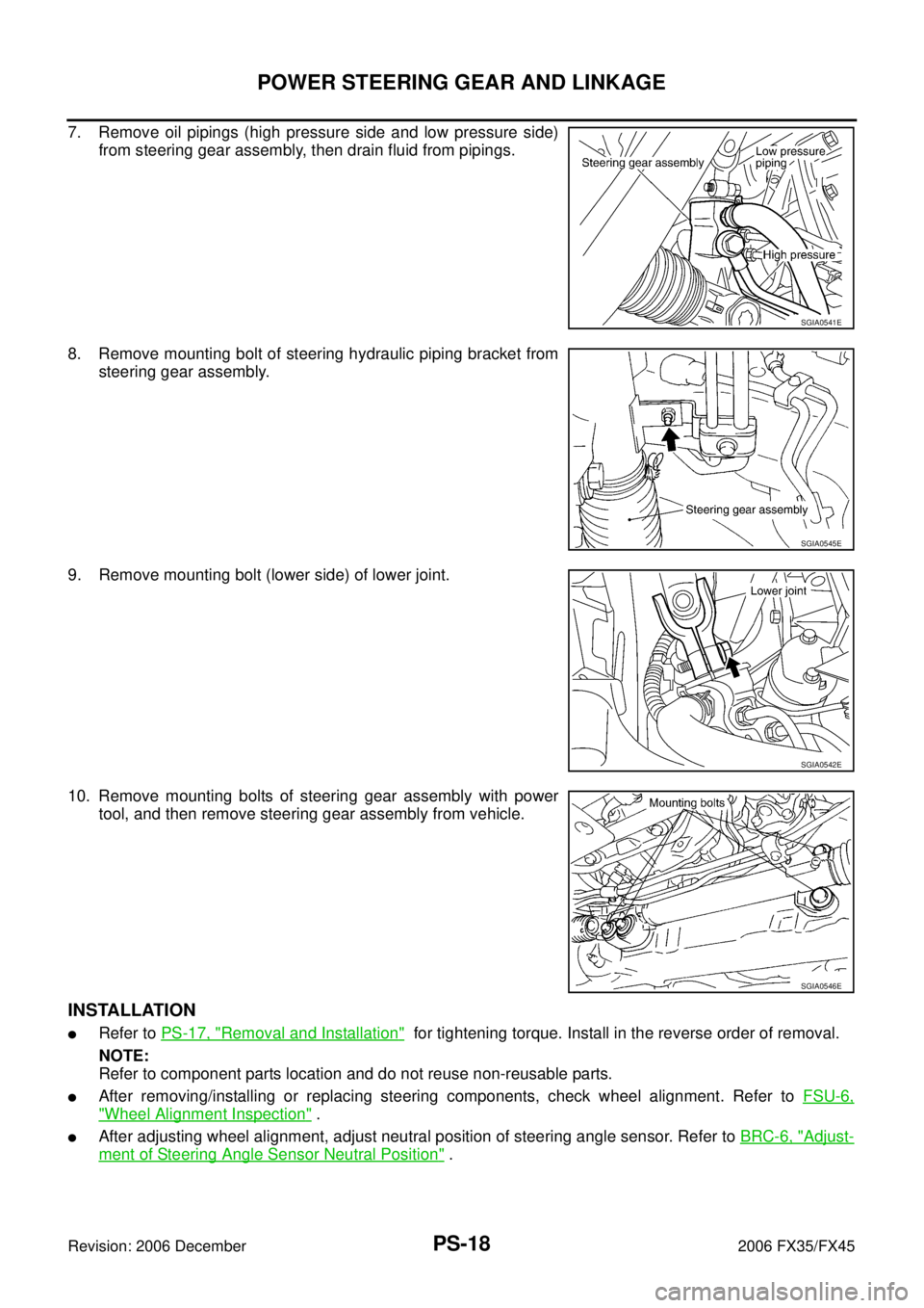
7. Remove oil pipings (high pressure side and low pressure side) from steering gear assembly, then drain fluid from pipings.
8. Remove mounting bolt of steering hydraulic piping bracket from steering gear assembly.
9. Remove mounting bolt (lower side) of lower joint.
10. Remove mounting bolts of steering gear assembly with power tool, and then remove steering gear assembly from vehicle.
INSTALLATION
�Refer to PS-17, "Removal and Installation" for tightening torque. Install in the reverse order of removal.
NOTE:
Refer to component parts location and do not reuse non-reusable parts.
�After removing/installing or replacing steering components, check wheel alignment. Refer to FSU-6,
"Wheel Alignment Inspection" .
�After adjusting wheel alignment, adjust neutral position of steering angle sensor. Refer to BRC-6, "Adjust-
ment of Steering Angle Sensor Neutral Position" .
SGIA0541E
SGIA0545E
SGIA0542E
SGIA0546E
Page 3992 of 4462

PS-44
SERVICE DATA AND SPECIFICATIONS (SDS)
Revision: 2006 December 2006 FX35/FX45
SERVICE DATA AND SPECIFICATIONS (SDS)PFP:00030
Steering WheelNGS000CE
Steering AngleNGS000CF
Steering ColumnNGS000CG
Steering Outer Socket and Inner SocketNGS000CH
End play of the axle direction for steering wheel 0 mm (0 in)
Steering wheel play on the outer circumference 0 − 35 mm (0 − 1.38 in)
Inner wheel
Degree minute (Decimal degree) Minimum 32
°00 ′ (32.0 °)
Nominal 35 °00 ′ (35.0 °)
Maximum 36 °00 ′ (36.0 °)
Outer wheel
Degree minute (Decimal degree) Nominal 30
°00 ′ (30.0 °)
Steering column length “ L1 ” 572 mm (22.52 in)
SGIA0556E
Steering gear type PR26AM
Tie-rod ball joint outer socket Swinging torque 0.3
− 2.9 N·m (0.03 − 0.29 kg-m, 3 − 25 in-lb)
Measurement on spring balance
�Measuring point: cotter pin hole of stud 4.84
− 46.7 N (0.5 − 4.8 kg, 1.0 − 10 lb)
Rotating torque 0.3 − 2.9 N·m (0.03 − 0.29 kg-m, 3 − 25 in-lb)
Axial end play 0.5 mm (0.02 in) or less
Tie-rod ball joint inner socket Swinging torque 1.0
− 7.8 N·m (0.11 − 0.79 kg-m, 9 − 69 in-lb)
Measurement on spring balance
�Measuring point: L mark see below,
L=83.2 mm (3.28 in). 12.1
− 93.7 N (1.2 − 9.6 kg, 3.0 − 21 lb)
Axial end play 0.2 mm (0.01 in) or less
SGIA0358E
Page 3997 of 4462
PREPARATION RAX-3
C E F
G H
I
J
K L
M A
B
RAX
Revision: 2006 December 2006 FX35/FX45
PREPARATIONPFP:00002
Special Service Tools (SST)NDS000CE
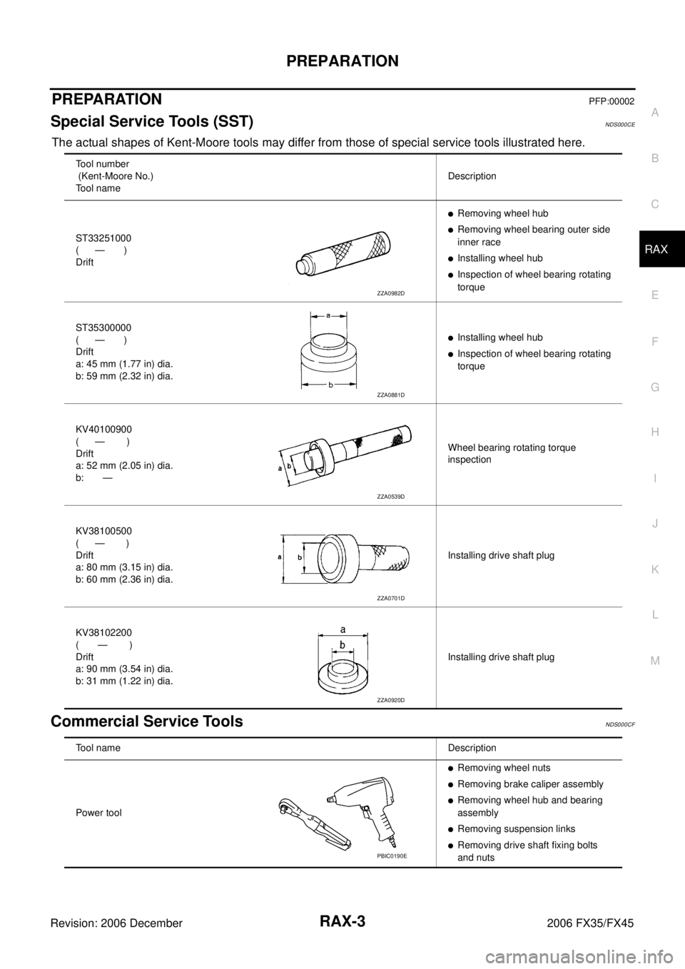
The actual shapes of Kent-Moore tools may differ from those of special service tools illustrated here.
Commercial Service ToolsNDS000CF
Tool number
(Kent-Moore No.)
Tool name Description
ST33251000
( — )
Drift
�Removing wheel hub
�Removing wheel bearing outer side
inner race
�Installing wheel hub
�Inspection of wheel bearing rotating
torque
ST35300000
( — )
Drift
a: 45 mm (1.77 in) dia.
b: 59 mm (2.32 in) dia.
�Installing wheel hub
�Inspection of wheel bearing rotating
torque
KV40100900
( — )
Drift
a: 52 mm (2.05 in) dia.
b: — Wheel bearing rotating torque
inspection
KV38100500
( — )
Drift
a: 80 mm (3.15 in) dia.
b: 60 mm (2.36 in) dia. Installing drive shaft plug
KV38102200
( — )
Drift
a: 90 mm (3.54 in) dia.
b: 31 mm (1.22 in) dia. Installing drive shaft plug
ZZA0982D
ZZA0881D
ZZA0539D
ZZA0701D
ZZA0920D
Tool name
Description
Power tool
�Removing wheel nuts
�Removing brake caliper assembly
�Removing wheel hub and bearing
assembly
�Removing suspension links
�Removing drive shaft fixing bolts
and nutsPBIC0190E