Page 193 of 4462
DTC P0615 START SIGNAL CIRCUIT AT-109
D E
F
G H
I
J
K L
M A
B
AT
Revision: 2006 December 2006 FX35/FX45
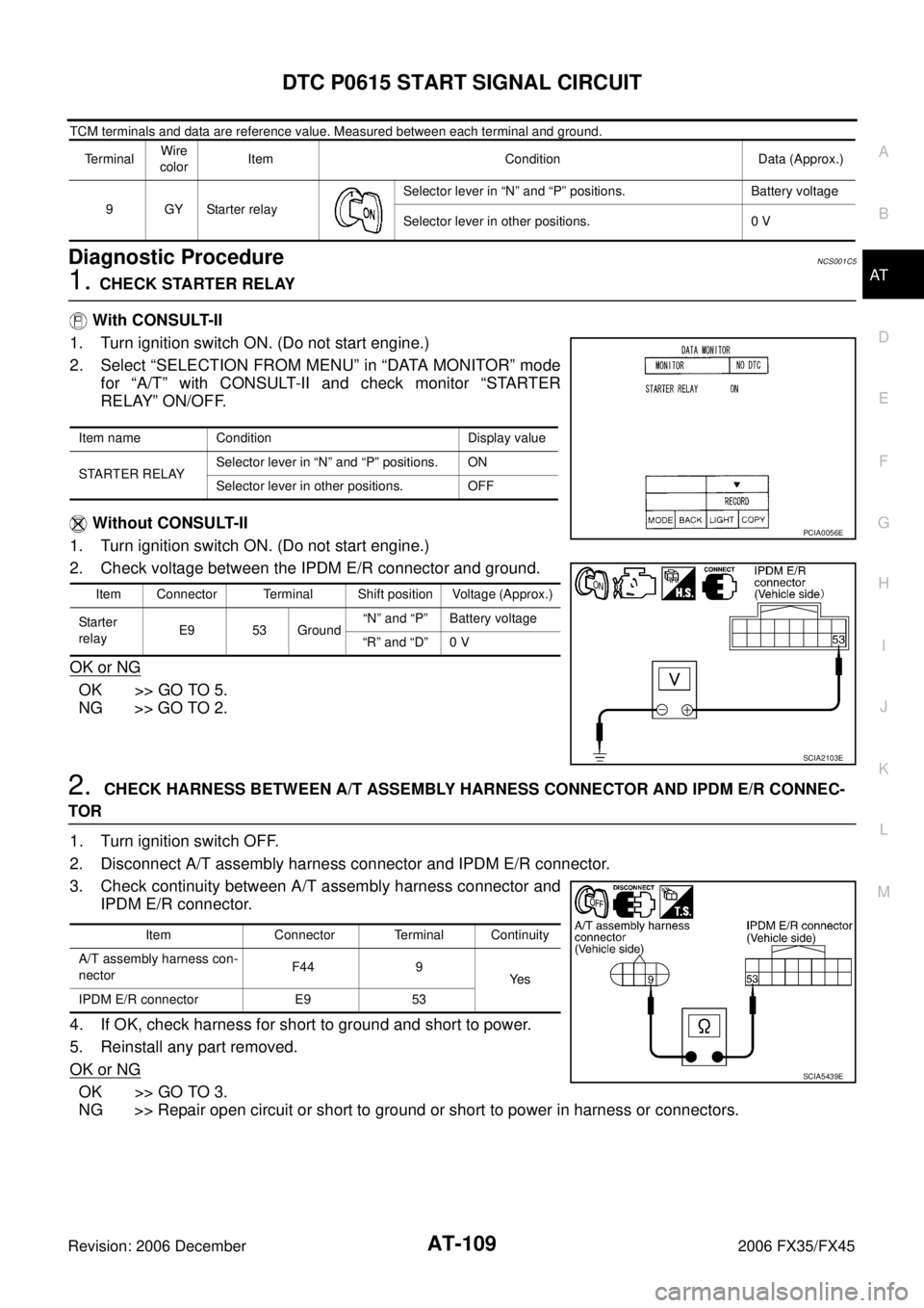
TCM terminals and data are reference value. Measured between each terminal and ground.
Diagnostic ProcedureNCS001C5
1. CHECK STARTER RELAY
With CONSULT-II
1. Turn ignition switch ON. (Do not start engine.)
2. Select “SELECTION FROM MENU” in “DATA MONITOR” mode for “A/T” with CONSULT-II and check monitor “STARTER
RELAY” ON/OFF.
Without CONSULT-II
1. Turn ignition switch ON. (Do not start engine.)
2. Check voltage between the IPDM E/R connector and ground.
OK or NG
OK >> GO TO 5.
NG >> GO TO 2.
2. CHECK HARNESS BETWEEN A/T ASSEMBLY HARNESS CONNECTOR AND IPDM E/R CONNEC-
TOR
1. Turn ignition switch OFF.
2. Disconnect A/T assembly harness connector and IPDM E/R connector.
3. Check continuity between A/T assembly harness connector and IPDM E/R connector.
4. If OK, check harness for short to ground and short to power.
5. Reinstall any part removed.
OK or NG
OK >> GO TO 3.
NG >> Repair open circuit or short to ground or short to power in harness or connectors.
Terminal Wire
color Item Condition Data (Approx.)
9GYStarter relay Selector lever in “N” and “P” positions. Battery voltage
Selector lever in other positions. 0 V
Item name Condition Display value
STARTER RELAY Selector lever in “N” and “P” positions. ON
Selector lever in other positions. OFF
Item Connector Terminal Shift position Voltage (Approx.)
Sta rter
relay E9 53 Ground “N” and “P” Battery voltage
“R” and “D” 0 V
PCIA0056E
SCIA2103E
Item Connector Terminal Continuity
A/T assembly harness con-
nector F44 9
Ye s
IPDM E/R connector E9 53
SCIA5439E
Page 194 of 4462
AT-110
DTC P0615 START SIGNAL CIRCUIT
Revision: 2006 December 2006 FX35/FX45
3. CHECK TERMINAL CORD ASSEMBLY
1. Remove control valve with TCM. Refer to AT- 2 3 9 , "
Control Valve with TCM and A/T Fluid Temperature
Sensor 2" .
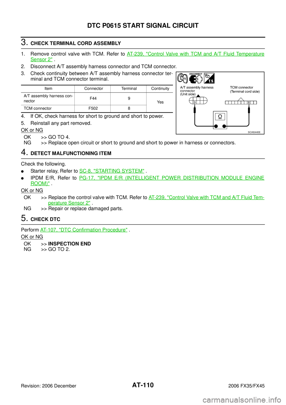
2. Disconnect A/T assembly harness connector and TCM connector.
3. Check continuity between A/T assembly harness connector ter- minal and TCM connector terminal.
4. If OK, check harness for short to ground and short to power.
5. Reinstall any part removed.
OK or NG
OK >> GO TO 4.
NG >> Replace open circuit or short to ground and short to power in harness or connectors.
4. DETECT MALFUNCTIONING ITEM
Check the following.
�Starter relay, Refer to SC-8, "STARTING SYSTEM" .
�IPDM E/R, Refer to PG-17, "IPDM E/R (INTELLIGENT POWER DISTRIBUTION MODULE ENGINE
ROOM)" .
OK or NG
OK >> Replace the control valve with TCM. Refer to AT- 2 3 9 , "Control Valve with TCM and A/T Fluid Tem-
perature Sensor 2" .
NG >> Repair or replace damaged parts.
5. CHECK DTC
Perform AT- 1 0 7 , "
DTC Confirmation Procedure" .
OK or NG
OK >> INSPECTION END
NG >> GO TO 2.
Item Connector Terminal Continuity
A/T assembly harness con-
nector F44 9
Ye s
TCM connector F502 8
SCIA5440E
Page 198 of 4462
AT-114
DTC P0705 PARK/NEUTRAL POSITION SWITCH
Revision: 2006 December 2006 FX35/FX45
Diagnostic ProcedureNCS001CH
1. CHECK PNP SW CIRCUIT
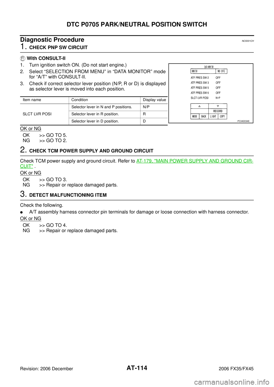
With CONSULT-II
1. Turn ignition switch ON. (Do not start engine.)
2. Select “SELECTION FROM MENU” in “DATA MONITOR” mode for “A/T” with CONSULT-II.
3. Check if correct selector lever position (N/P, R or D) is displayed as selector lever is moved into each position.
OK or NG
OK >> GO TO 5.
NG >> GO TO 2.
2. CHECK TCM POWER SUPPLY AND GROUND CIRCUIT
Check TCM power supply and ground circuit. Refer to AT- 1 7 9 , "
MAIN POWER SUPPLY AND GROUND CIR-
CUIT" .
OK or NG
OK >> GO TO 3.
NG >> Repair or replace damaged parts.
3. DETECT MALFUNCTIONING ITEM
Check the following.
�A/T assembly harness connector pin terminals for damage or loose connection with harness connector.
OK or NG
OK >> GO TO 4.
NG >> Repair or replace damaged parts.
Item name Condition Display value
SLCT LVR POSI Selector lever in N and P positions. N/P
Selector lever in R position. R
Selector lever in D position. D
PCIA0034E
Page 199 of 4462

DTC P0705 PARK/NEUTRAL POSITION SWITCH AT-115
D E
F
G H
I
J
K L
M A
B
AT
Revision: 2006 December 2006 FX35/FX45
4. CHECK SUB-HARNESS
1. Remove control valve with TCM. Refer to AT- 2 3 9 , "
Control Valve with TCM and A/T Fluid Temperature
Sensor 2" .
2. Disconnect park/neutral position switch connector and TCM connector.
3. Check continuity between park/neutral position switch connector terminals and TCM connector terminals.
4. If OK, check harness for short to ground and short to power.
5. Reinstall any part removed.
OK or NG
OK >> Replace the control valve with TCM. Refer to AT- 2 3 9 , "Control Valve with TCM and A/T Fluid Tem-
perature Sensor 2" .
NG >> Replace open circuit or short to ground and short to power in harness or connectors.
5. CHECK DTC
Perform AT- 11 2 , "
DTC Confirmation Procedure" .
OK or NG
OK >> INSPECTION END
NG >> GO TO 2.
Item Connector Terminal Continuity
Park/neutral position switch
connector F505 1
Ye s
TCM connector F503 13
Park/neutral position switch
connector F505 2
Ye s
TCM connector F503 11
Park/neutral position switch
connector F505 3
Ye s
TCM connector F503 12
Park/neutral position switch
connector F505 5
Ye s
TCM connector F503 14
SCIA5457E
Page 201 of 4462

DTC P0717 TURBINE REVOLUTION SENSOR AT-117
D E
F
G H
I
J
K L
M A
B
AT
Revision: 2006 December 2006 FX35/FX45
Diagnostic ProcedureNCS001E6
1. CHECK INPUT SIGNAL
With CONSULT-II
1. Start engine.
2. Select “ECU INPUT SIGNALS” in “DATA MONITOR” mode for “A/T” with CONSULT-II.
3. Vehicle start and read out the value of “TURBINE REV”.
OK or NG
OK >> GO TO 4.
NG >> GO TO 2.
2. CHECK TCM POWER SUPPLY AND GROUND CIRCUIT
Check TCM power supply and ground circuit. Refer to AT- 1 7 9 , "
MAIN POWER SUPPLY AND GROUND CIR-
CUIT" .
OK or NG
OK >> GO TO 3.
NG >> Repair or replace damaged parts.
3. DETECT MALFUNCTIONING ITEM
Check the following.
�A/T assembly harness connector pin terminals for damage or loose connection with harness connector.
OK or NG
OK >> Replace the control valve with TCM. Refer to AT- 2 3 9 , "Control Valve with TCM and A/T Fluid Tem-
perature Sensor 2" .
NG >> Repair or replace damaged parts.
4. CHECK DTC
Perform AT- 11 6 , "
DTC Confirmation Procedure" .
OK or NG
OK >> INSPECTION END
NG >> GO TO 2.
Item name Condition Display value (rpm)
TURBINE REV During driving (lock-up ON) Approximately matches
the engine speed.
PCIA0041E
Page 205 of 4462
DTC P0720 VEHICLE SPEED SENSOR A/T (REVOLUTION SENSOR) AT-121
D E
F
G H
I
J
K L
M A
B
AT
Revision: 2006 December 2006 FX35/FX45
Diagnostic ProcedureNCS001CO
1. CHECK INPUT SIGNAL
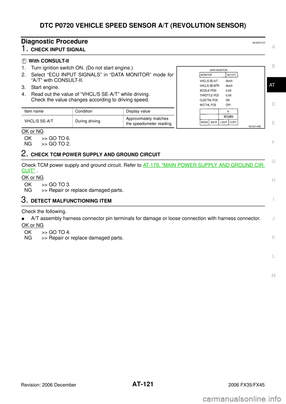
With CONSULT-II
1. Turn ignition switch ON. (Do not start engine.)
2. Select “ECU INPUT SIGNALS” in “DATA MONITOR” mode for “A/T” with CONSULT-II.
3. Start engine.
4. Read out the value of “VHCL/S SE-A/T” while driving. Check the value changes according to driving speed.
OK or NG
OK >> GO TO 6.
NG >> GO TO 2.
2. CHECK TCM POWER SUPPLY AND GROUND CIRCUIT
Check TCM power supply and ground circuit. Refer to AT- 1 7 9 , "
MAIN POWER SUPPLY AND GROUND CIR-
CUIT" .
OK or NG
OK >> GO TO 3.
NG >> Repair or replace damaged parts.
3. DETECT MALFUNCTIONING ITEM
Check the following.
�A/T assembly harness connector pin terminals for damage or loose connection with harness connector.
OK or NG
OK >> GO TO 4.
NG >> Repair or replace damaged parts.
Item name Condition Display value
VHCL/S SE-A/T During driving Approximately matches
the speedometer reading.
SCIA2148E
Page 206 of 4462

AT-122
DTC P0720 VEHICLE SPEED SENSOR A/T (REVOLUTION SENSOR)
Revision: 2006 December 2006 FX35/FX45
4. CHECK SUB-HARNESS
1. Remove control valve with TCM. Refer to AT- 2 3 9 , "
Control Valve with TCM and A/T Fluid Temperature
Sensor 2" .
2. Disconnect park/neutral position switch connector and TCM connector.
3. Check continuity between park/neutral position switch connector terminals and TCM connector terminals.
4. If OK, check harness for short to ground and short to power.
5. Reinstall any part removed.
OK or NG
OK >> GO TO 5.
NG >> Replace open circuit or short to ground and short to power in harness or connectors.
5. REPLACE THE REVOLUTION SENSOR AND CHECK DTC
1. Replace the revolution sensor. Refer to AT- 2 5 9 , "
Revolution Sensor Components (2WD Models Only)"
(2WD models) or AT- 2 9 4 , "Disassembly" , AT- 2 7 4 , "Components" (AWD models).
2. Perform AT- 11 8 , "
DTC Confirmation Procedure" .
OK or NG
OK >> INSPECTION END
NG >> Replace the control valve with TCM. Refer to AT- 2 3 9 , "
Control Valve with TCM and A/T Fluid Tem-
perature Sensor 2" .
6. CHECK DTC
Perform AT- 11 8 , "
DTC Confirmation Procedure" .
OK or NG
OK >> INSPECTION END
NG >> GO TO 2.
Item Connector Terminal Continuity
Park/neutral position switch
connector F505 8
Ye s
TCM connector F503 20
Park/neutral position switch
connector F505 9
Ye s
TCM connector F503 17
Park/neutral position switch
connector F505 10
Ye s
TCM connector F503 16
SCIA5458E
Page 208 of 4462
AT-124
DTC P0725 ENGINE SPEED SIGNAL
Revision: 2006 December 2006 FX35/FX45
Diagnostic ProcedureNCS001CU
1. CHECK CAN COMMUNICATION LINE
Perform the self-diagnosis. Refer to AT- 9 2 , "
SELF-DIAGNOSTIC RESULT MODE" , AT- 1 0 2 , "Diagnostic Pro-
cedure without CONSULT-II" .
Is a malfunction in the CAN communication indicated in the results?
YES >> Check CAN communication line. Refer to AT- 1 0 4 , "DTC U1000 CAN COMMUNICATION LINE" .
NO >> GO TO 2.
2. CHECK DTC WITH TCM
With CONSULT-II
1. Start engine.
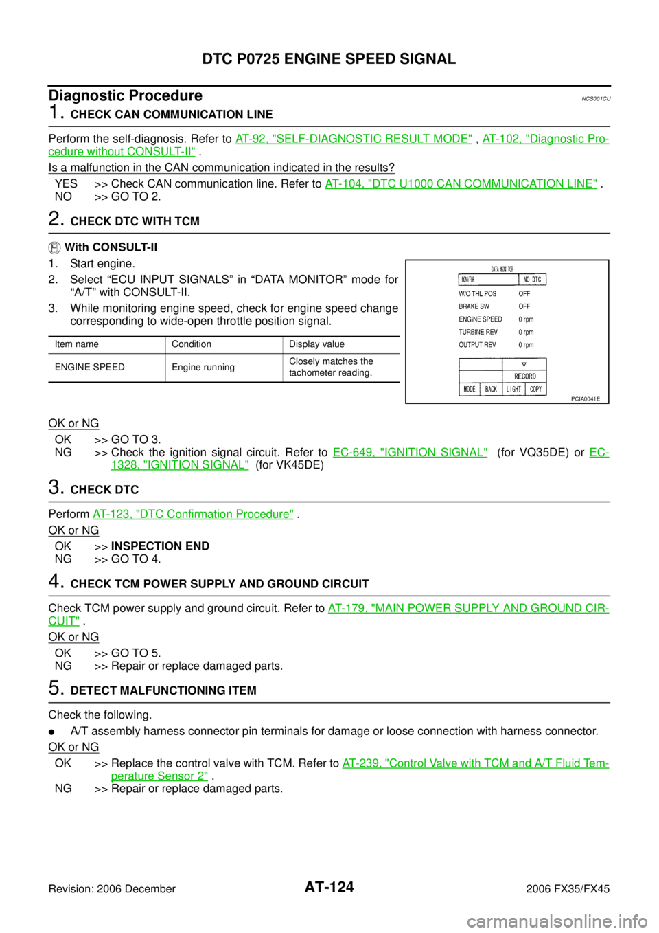
2. Select “ECU INPUT SIGNALS” in “DATA MONITOR” mode for “A/T” with CONSULT-II.
3. While monitoring engine speed, check for engine speed change corresponding to wide-open throttle position signal.
OK or NG
OK >> GO TO 3.
NG >> Check the ignition signal circuit. Refer to EC-649, "
IGNITION SIGNAL" (for VQ35DE) or EC-
1328, "IGNITION SIGNAL" (for VK45DE)
3. CHECK DTC
Perform AT- 1 2 3 , "
DTC Confirmation Procedure" .
OK or NG
OK >> INSPECTION END
NG >> GO TO 4.
4. CHECK TCM POWER SUPPLY AND GROUND CIRCUIT
Check TCM power supply and ground circuit. Refer to AT- 1 7 9 , "
MAIN POWER SUPPLY AND GROUND CIR-
CUIT" .
OK or NG
OK >> GO TO 5.
NG >> Repair or replace damaged parts.
5. DETECT MALFUNCTIONING ITEM
Check the following.
�A/T assembly harness connector pin terminals for damage or loose connection with harness connector.
OK or NG
OK >> Replace the control valve with TCM. Refer to AT- 2 3 9 , "Control Valve with TCM and A/T Fluid Tem-
perature Sensor 2" .
NG >> Repair or replace damaged parts.
Item name Condition Display value
ENGINE SPEED Engine running Closely matches the
tachometer reading.
PCIA0041E