Page 317 of 4462
A/T SHIFT LOCK SYSTEM AT-233
D E
F
G H
I
J
K L
M A
B
AT
Revision: 2006 December 2006 FX35/FX45
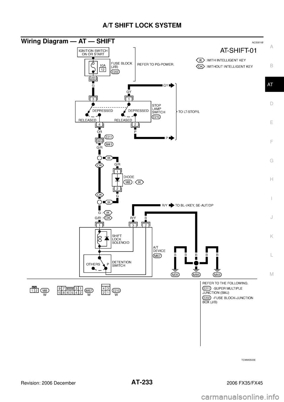
Wiring Diagram — AT — SHIFTNCS001IB
TCWM0503E
Page 318 of 4462

AT-234
A/T SHIFT LOCK SYSTEM
Revision: 2006 December 2006 FX35/FX45
Diagnostic ProcedureNCS001IC
SYMPTOM 1:
�Selector lever cannot be moved from “P” position with key in ON position and brake pedal
applied.
�Selector lever can be moved from “P” position with key in ON position and brake pedal released.
�Selector lever can be moved from “P” position when key is removed from key cylinder.
SYMPTOM 2:
�Ignition key cannot be removed when selector lever is set to “P” position.
�Ignition key can be removed when selector lever is set to any position except “P” position.
1. CHECK KEY INTERLOCK CABLE
Check the key interlock cable for damage.
OK or NG
OK >> GO TO 2.
NG >> Repair or replace key interlock cable. Refer to AT- 2 3 6 , "
KEY INTERLOCK CABLE" .
2. CHECK SELECTOR LEVER POSITION
Check the selector lever position for damage. Refer to AT- 2 3 1 , "
Checking of A/T Position"
OK or NG
OK >> GO TO 3.
NG >> Adjust A/T position. Refer to AT- 2 3 1 , "
Adjustment of A/T Position" .
3. CHECK SHIFT LOCK SOLENOID AND PARK POSITION SWITCH
1. Connect A/T device harness connector.
2. Turn ignition switch ON. (Do not start engine.)
3. Selector lever is set in “P” position.
4. Check operation.
OK or NG
OK >> INSPECTION END
NG >> GO TO 4.
4. CHECK POWER SOURCE
1. Turn ignition switch ON. (Do not start engine.)
2. Check the voltage between A/T device harness connector M67 terminal 1 and ground. Refer to AT- 2 3 3 , "
Wiring Diagram — AT
— SHIFT" .
OK or NG
OK >> GO TO 7.
NG >> GO TO 5.
Condition Brake pedal Operation
When ignition switch is turned to ON and selector lever is set in
“P” position. Depressed Yes
Released No
Condition Brake pedal Data (Approx.)
When ignition switch is turned to
ON. Depressed Battery voltage
Released 0 V
SCIA2122E
Page 319 of 4462

A/T SHIFT LOCK SYSTEM AT-235
D E
F
G H
I
J
K L
M A
B
AT
Revision: 2006 December 2006 FX35/FX45
5. CHECK STOP LAMP SWITCH
1. Turn ignition switch OFF.
2. Disconnect stop lamp switch harness connector.
3. Check continuity between stop lamp switch harness connector E210 terminals 3 and 4.
Check stop lamp switch after adjusting brake pedal — refer to
BR-6, "
BRAKE PEDAL" .
OK or NG
OK >> GO TO 6.
NG >> Repair or replace damaged parts.
6. DETECT MALFUNCTIONING ITEM
Check the following items. If any items are damaged, repair or replace damaged parts.
�Harness for short or open between ignition switch and stop lamp switch harness connector E210 terminal
3.
�Harness for short or open between stop lamp switch harness connector E210 terminal 4 and A/T device
harness connector M67 terminal 1.
�10 A fuse [No.12, located in the fuse block (J/B)].
�Ignition switch, Refer to PG-3, "POWER SUPPLY ROUTING CIRCUIT" .
OK or NG
OK >> INSPECTION END
NG >> Repair or replace damaged parts.
7. CHECK GROUND CIRCUIT
1. Turn ignition switch OFF.
2. Disconnect A/T device harness connector.
3. Check continuity between A/T device harness connector M67 terminal 2 and ground.
OK or NG
OK >> Replace shift lock solenoid and park position switch assembly.
NG >> Repair open circuit in harness or connectors.
Condition Continuity
When brake pedal is depressed Yes
When brake pedal is released No
SCIA2126E
Continuity should exist.
SCIA2125E
Page 682 of 4462

AV-76
INTEGRATED DISPLAY SYSTEM
Revision: 2006 December 2006 FX35/FX45
Self-Diagnosis Mode (DCU)NKS003JD
OPERATION PROCEDURE
1. Start the engine.
2. Turn the audio system OFF.
3. While pressing the “4” button, turn the volume control dial clock- wise or counterclockwise for 30 clicks or more. (When the self-
diagnosis mode is started, a short beep will be heard.)
�Shifting from current screen to previous screen is performed
by pressing “BACK” button.
4. The initial trouble diagnosis screen will be shown, and items “Self Diagnosis (DCU)”, “Confirmation/Adjustment” and “CAN
DIAG SUPPORT MONITOR” will become selective.
5. Perform self-diagnosis by selecting the “Self Diagnosis (DCU)”.
�Self-diagnosis screen is displayed, and then self-diagnosis
starts.
�The bar graph visible below self-diagnosis screen displays
progress of the diagnosis.
6. When the self-diagnosis completes, optional part confirmation screen will be shown.
�When connection of an optional part is judged error, a screen
to check if the optional part is actually fitted on the vehicle or
not will be shown. When fitted, select the switch of the part on
the screen and press “End”. Then the “SELF DIAGNOSIS”
screen will be shown.
�When the optional part is connected normally, the switch for
the part will not appear on the screen.
SKIB8743E
SKIB7871E
SKIA4208E
SKIB8673E
Page 685 of 4462
INTEGRATED DISPLAY SYSTEM AV-79
C
D E
F
G H
I
J
L
M A
B
AV
Revision: 2006 December 2006 FX35/FX45
Confirmation/Adjustment ModeNKS003JE
OPERATION PROCEDURE
1. Start the engine.
2. Turn the audio system OFF.
3. While pressing the “4” button, turn the volume control dial clock- wise or counterclockwise for 30 clicks or more. (When the self-
diagnosis mode is started, a short beep will be heard.)
�Shifting from current screen to previous screen is performed
by pressing “BACK” button.
4. The initial trouble diagnosis screen will be shown, and items “Self Diagnosis (DCU)”, “Confirmation/Adjustment” and “CAN
DIAG SUPPORT MONITOR” will become selective.
5. Select “Confirmation/Adjustment”.
6. Each diagnosis is shown by selecting each screen switch on Confirmation/Adjustment screen.
SKIB8743E
SKIB7871E
SKIB7873E
Page 687 of 4462

INTEGRATED DISPLAY SYSTEM AV-81
C
D E
F
G H
I
J
L
M A
B
AV
Revision: 2006 December 2006 FX35/FX45
AUTO CLIMATE CONTROL
Refer to AT C - 5 2 , "Self-diagnosis Function" .
CAN DIAG SUPPORT MONITORNKS003JF
OPERATION PROCEDURE
1. Start the engine.
2. Turn the audio system OFF.
3. While pressing the “4” button, turn the volume control dial clock- wise or counterclockwise for 30 clicks or more. (When the self-
diagnosis mode is started, a short beep will be heard.)
�Shifting from current screen to previous screen is performed
by pressing “BACK” button.
4. The initial trouble diagnosis screen will be shown, and items “Self Diagnosis (DCU)”, “Confirmation/Adjustment” and “CAN
DIAG SUPPORT MONITOR” will become selective.
5. Select “CAN DIAG SUPPORT MONITOR”.
6. The transmitting/receiving of CAN communication can be moni- tored.
NOTE:
Counter shows the status of CAN communication.
SKIB8743E
SKIB7871E
Item Content Error counter
(Reference value)
CAN_COMM OK/NG 0 - 50
CAN_CIRC_1 OK/UNKWN 0 - 50
CAN_CIRC_2 OK/UNKWN 0 - 50
CAN_CIRC_3 OK/UNKWN 0 - 50
CAN_CIRC_4 OK/UNKWN 0 - 50
CAN_CIRC_5 OK/UNKWN 0 - 50
CAN_CIRC_6 OK/UNKWN 0 - 50
CAN_CIRC_7 OK/UNKWN 0 - 50
CAN_CIRC_8 OK/UNKWN 0 - 50
CAN_CIRC_9 OK/UNKWN 0 - 50
SKIA4288E
Page 729 of 4462
NAVIGATION SYSTEM AV-123
C
D E
F
G H
I
J
L
M A
B
AV
Revision: 2006 December 2006 FX35/FX45
Self-Diagnosis Mode (DCU)NKS003KF
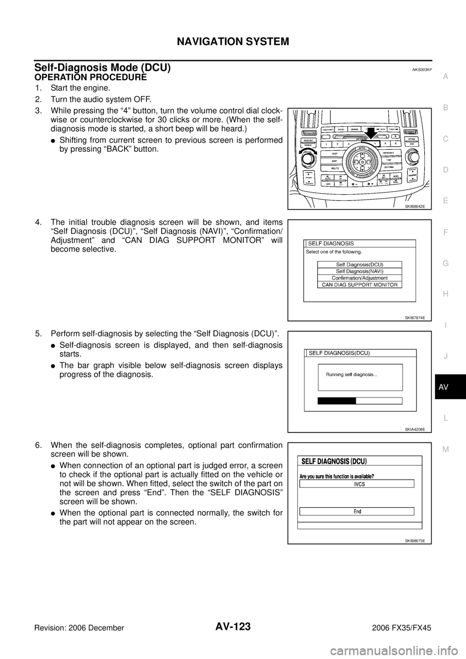
OPERATION PROCEDURE
1. Start the engine.
2. Turn the audio system OFF.
3. While pressing the “4” button, turn the volume control dial clock- wise or counterclockwise for 30 clicks or more. (When the self-
diagnosis mode is started, a short beep will be heard.)
�Shifting from current screen to previous screen is performed
by pressing “BACK” button.
4. The initial trouble diagnosis screen will be shown, and items “Self Diagnosis (DCU)”, “Self Diagnosis (NAVI)”, “Confirmation/
Adjustment” and “CAN DIAG SUPPORT MONITOR” will
become selective.
5. Perform self-diagnosis by selecting the “Self Diagnosis (DCU)”.
�Self-diagnosis screen is displayed, and then self-diagnosis
starts.
�The bar graph visible below self-diagnosis screen displays
progress of the diagnosis.
6. When the self-diagnosis completes, optional part confirmation screen will be shown.
�When connection of an optional part is judged error, a screen
to check if the optional part is actually fitted on the vehicle or
not will be shown. When fitted, select the switch of the part on
the screen and press “End”. Then the “SELF DIAGNOSIS”
screen will be shown.
�When the optional part is connected normally, the switch for
the part will not appear on the screen.
SKIB8642E
SKIB7874E
SKIA4208E
SKIB8673E
Page 732 of 4462
AV-126
NAVIGATION SYSTEM
Revision: 2006 December 2006 FX35/FX45
Self-Diagnosis Mode (NAVI)NKS003KG
OPERATION PROCEDURE
1. Start the engine.
2. Turn the audio system OFF.
3. While pressing the “4” button, turn the volume control dial clock- wise or counterclockwise for 30 clicks or more. (When the self-
diagnosis mode is started, a short beep will be heard.)
�Shifting from current screen to previous screen is performed
by pressing “BACK” button.
4. The initial trouble diagnosis screen will be shown, and items “Self Diagnosis (DCU)”, “Self Diagnosis (NAVI)”, “Confirmation/
Adjustment” and “CAN DIAG SUPPORT MONITOR” will
become selective.
NOTE:
Select “Self Diagnosis (DCU)” when “Self Diagnosis (NAVI)” is
not available. Repair malfunctioning part.
5. Perform self-diagnosis by selecting the “Self Diagnosis (NAVI)”.
�Self-diagnosis screen is displayed, and then self-diagnosis
starts.
�The bar graph visible below self-diagnosis screen displays
progress of the diagnosis.
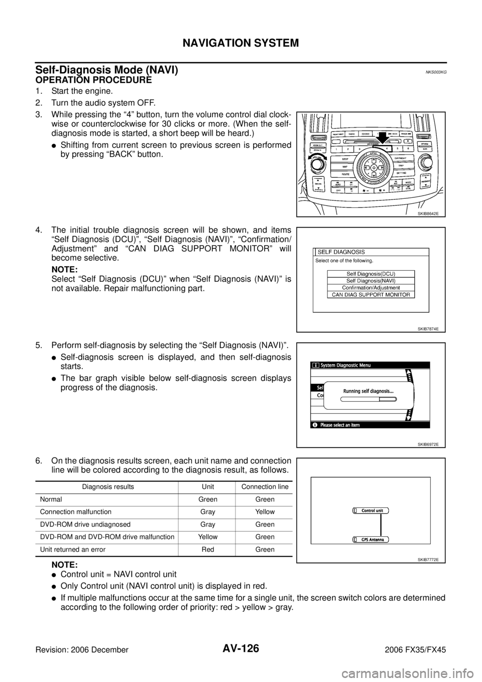
6. On the diagnosis results screen, each unit name and connection line will be colored according to the diagnosis result, as follows.
NOTE:
�Control unit = NAVI control unit
�Only Control unit (NAVI control unit) is displayed in red.
�If multiple malfunctions occur at the same time for a single unit, the screen switch colors are determined
according to the following order of priority: red > yellow > gray.
SKIB8642E
SKIB7874E
SKIB6972E
Diagnosis results Unit Connection line
Normal Green Green
Connection malfunction Gray Yellow
DVD-ROM drive undiagnosed Gray Green
DVD-ROM and DVD-ROM drive malfunction Yellow Green
Unit returned an error Red Green
SKIB7772E